US5259290A - Ammunition container - Google Patents
Ammunition container Download PDFInfo
- Publication number
- US5259290A US5259290A US07/921,635 US92163592A US5259290A US 5259290 A US5259290 A US 5259290A US 92163592 A US92163592 A US 92163592A US 5259290 A US5259290 A US 5259290A
- Authority
- US
- United States
- Prior art keywords
- ammunition
- control lever
- container
- ammunition container
- longitudinal axis
- Prior art date
- Legal status (The legal status is an assumption and is not a legal conclusion. Google has not performed a legal analysis and makes no representation as to the accuracy of the status listed.)
- Expired - Fee Related
Links
- 238000000034 method Methods 0.000 description 2
- 230000006978 adaptation Effects 0.000 description 1
- 230000002950 deficient Effects 0.000 description 1
- 239000002360 explosive Substances 0.000 description 1
- 238000003780 insertion Methods 0.000 description 1
- 230000037431 insertion Effects 0.000 description 1
- 238000012986 modification Methods 0.000 description 1
- 230000004048 modification Effects 0.000 description 1
- 230000000717 retained effect Effects 0.000 description 1
Images


Classifications
-
- F—MECHANICAL ENGINEERING; LIGHTING; HEATING; WEAPONS; BLASTING
- F41—WEAPONS
- F41A—FUNCTIONAL FEATURES OR DETAILS COMMON TO BOTH SMALLARMS AND ORDNANCE, e.g. CANNONS; MOUNTINGS FOR SMALLARMS OR ORDNANCE
- F41A9/00—Feeding or loading of ammunition; Magazines; Guiding means for the extracting of cartridges
- F41A9/61—Magazines
- F41A9/64—Magazines for unbelted ammunition
- F41A9/76—Magazines having an endless-chain conveyor
Definitions
- the present invention relates to an ammunition container for large caliber ammunition, particularly armored vehicle ammunition.
- the invention relates to an ammunition container of the type wherein large caliber ammunition is held by at least two shells arranged parallel to the ammunition, with one shell being fixed and the other shell being movable.
- the invention also relates to the use of such ammunition containers in magazine belts, particularly for ammunition having combustible casings.
- a significant problem involved with the storage of large caliber ammunition having thin-walled casings (particularly combustible casings) in ammunition containers for magazine belts is that this ammunition must be tied down securely (lashed) in the containers when the vehicle travels through uneven terrain. Otherwise the ammunition may become prematurely defective and thus useless due to shaking.
- DE 3,046,642.A2 discloses ammunition containers composed of two shell halves which enclose the ammunition, with one of the shells being a fixed shell and the other a movable shell. This ammunition container does not provide for tying down the ammunition.
- U.S. Pat. No. 4,619,181 discloses an ammunition container which is essentially composed of one half shell. In the region of the projectile head and the casing bottom, separate holding clamps are provided to tie down the ammunition. The drawback of this arrangement is, however, that the ammunition can be removed only at the points where the ammunition belt reverses since the holding clamps permit only a limited opening angle.
- the invention is essentially based on the concept of providing a two-stage motion sequence for loading the ammunition containers.
- the movable shell In the first stage the movable shell is placed around the ammunition in the circumferential direction so that the ammunition is disposed between the two shells.
- the movable shell In the second stage the movable shell is then moved radially toward the ammunition so that the ammunition is firmly clamped between the shells.
- This two-stage motion sequence is realized with the aid of a control lever whose pivot axis coincides with the longitudinal axis of the ammunition container.
- the control lever has a cam.
- the control lever is connected with the movable shell by way of a releasable holding mechanism in such a manner that the shell is rotated along when the control lever is pivoted from an open position to a closed position (a position in which the two shells are disposed approximately opposite one another).
- the movable shell is arranged to be freely rotatable on the cam of the control lever so that, after the holding mechanism has been released, continued pivoting of the control lever to a clamping position causes the movable shell to be moved in the direction of the ammunition.
- the further pivoting of the control lever takes place automatically by means of a pre-tensioned torsion spring so that a predetermined contact pressure is ensured.
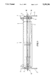
- FIG. 1 is a side view of an ammunition container according to the invention with inserted ammunition.
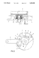
- FIG. 2 is a cross-sectional view of a container according to FIG. 1 in the region of the casing bottom of the ammunition.
- FIG. 3 is an end view of the ammunition container seen along the line III--III in FIG. 2.
- FIGS. 4a to 4c are a front, side, and rear view, respectively, of a control lever that can be used to pivot the movable shell.
- FIGS. 5a to 5d are end views showing various operating states of the ammunition container according to the invention.
- FIG. 6 is an end view illustrating an example of a magazine belt composed of the ammunition containers according to the invention, and shows possible removal positions.
- the ammunition container according to the invention is marked 1; ammunition 2 is stored in it.
- Reference numerals 3 and 3' and 4 and 4' identify chain links by means of which the ammunition container 1 can be connected with adjacent identical ammunition containers of a magazine belt.
- Ammunition container 1 is composed essentially of a fixed shell 5 and a movable shell 6.
- the shape of shells 5 and 6 is adapted to the ammunition 2 to be stored (in the illustrated example, ammunition 2 is a HEAT or high explosive anti-tank cartridge).
- ammunition 2 is a HEAT or high explosive anti-tank cartridge.
- two control levers 7 and 7' are indicated. These levers will be described in greater detail below.
- the longitudinal axis of ammunition container 1 is marked by reference numeral 12.
- FIG. 2 is a cross-sectional view of ammunition container 1 in the region of end 10, the end of the container in which the cartridge bottom of ammunition 2 is disposed.
- Reference numeral 8 identifies a flange pin which is attached to fixed shell 5.
- the lever 7 is pivotal around flange pin 8 about an axis coinciding with the longitudinal axis 12 of ammunition carrier 1.
- a torsion spring 72 biases lever 7 with respect to flange pin 8.
- Lever 7 is provided with a cam 70 which extends through a circular opening 6' in movable shell 6. Cam 70 is rotatable with respect to opening 6'.
- FIG. 3 An end view of end 10 of ammunition container 1, as seen along the section line marked III--III, is shown in FIG. 3.
- the control lever 7 has a detent groove 71.
- the control lever 7 is connected with movable shell 6 by way of a releasable holding mechanism or rocker detent 9.
- Rocker detent 9 is essentially composed of a rocker lever 90 which includes a joint 91 and a detent pin 92.
- the detent pin 92 engages in the detent groove 71 of control lever 7 in a force-transmitting manner so as to pivot movable shell 6 from a corresponding open position to a corresponding closed position.
- This closed position is reached when rocker lever 90 arrives at a stop 50. Stop 50 causes detent pin 92 of rocker lever 90 to slide out of detent groove 71.
- control lever 7 Upon further counterclockwise rotation of control lever 7, the movable shell 6 therefore no longer rotates along but, due to its arrangement on cam 70, is pressed against the ammunition 2 (which is shown in dashed lines in FIG. 3).
- the torsion spring 72 (not shown in FIG. 3) is permanently tensioned and takes care that the ammunition is essentially automatically clamped in and also that it is retained in this position.
- FIGS. 4a to 4c The structure of the control lever 7 is shown in FIGS. 4a to 4c.
- FIG. 4a shows the torsion spring 72, which is configured as a coil spring and is disposed in the interior of control lever 7.
- the first end 73 of torsion spring 72 is fastened to control lever 7 and the second end 74 to flange pin 8 (FIG. 2).
- FIGS. 4b and 4c clearly show detent groove 71 and cam 70.
- FIG. 5a shows the ammunition container 1 with control lever 7 in its open position.
- the two shells 5 and 6 lie close to one another and together form at most half of a cylinder so that the ammunition 2 can be removed from the container or placed into the container.
- container 1 has been loaded with ammunition 2 and can now be closed and the ammunition can be tied down.
- control lever 7 is pivoted counterclockwise. As can be seen in FIG. 5b, rotation of control lever 7 also rotates movable shell 6 since detent pin 92 is in force-transmitting engagement in detent groove 71. During this movement, cam 70 and opening 6' (FIG. 2) rotate in unison.
- control lever 7 is shown in its closed position.
- Rocker lever 90 has reached the stop 50, and a stop 60 on movable shell 6 has reached chain link 3 (in this position, the fixed shell 5 and the movable shell 6 are disposed opposite one another).
- This causes detent pin 92 to slide out of detent groove 71.
- Cam 70 is now free to rotate within opening 6' (FIG. 2).
- torsion spring 72 control lever 7 pivots until movable shell 6 encloses ammunition 2 without play (FIG. 5d), with cam 70 forcing movable shell 6 toward fixed shell 5 to clamp ammunition 2 between the shells.
- FIG. 5d shows control lever 7 in its clamping position.
- control lever 7 is turned back again by means of an external drive (not shown).
- the spring 72 is tensioned and the movable shell 6 is carried along until it reaches its starting position (FIG. 5a).
- movable shell 6 can be locked in its starting position.
- control lever 7 takes place in synchronism also for control lever 7' so that this lever need not be discussed in greater detail.
- FIG. 6 shows a magazine chain composed of ten ammunition containers.
- the letters A, B and C identify possible ammunition removal positions.
- ammunition containers according to the present invention are employed in a magazine chain it is possible (in contrast to the above-noted U.S. Pat. No. 4,619,181) to remove ammunition not only at positions near the outer reversal points but also, for example, at the linear belt sections.
Landscapes
- Engineering & Computer Science (AREA)
- General Engineering & Computer Science (AREA)
- Packaging Of Annular Or Rod-Shaped Articles, Wearing Apparel, Cassettes, Or The Like (AREA)
- Buckles (AREA)
- Portable Nailing Machines And Staplers (AREA)
- Details Of Rigid Or Semi-Rigid Containers (AREA)
Abstract
An ammunition container (1) for large caliber ammunition (2) includes two shells (5, 6) that are arranged parallel to the ammunition, with one shell (5) being fixed and the other shell (6) being movable. A rotatable control lever (7, 7') is mounted at least one end (10, 11) of the ammunition container (1), the control lever having a pivot axis that coincides with the longitudinal axis (12) of the ammunition container (1). The movable shell (6) and the control lever (7, 7') are connected with one another by way of a releasable holding mechanism (9) so that, upon pivoting of the control lever (7, 7') from an open position to a closed position, the movable shell (6) also rotates about the longitudinal axis (12) of the ammunition container. In addition, the control lever (7, 7') has a cam (70) on which the movable shell (6) is mounted so as to be freely rotatable. The cam (70 ) causes the movable shell to be pressed radially against the ammunition (2) when the control lever (7, 7') is pivoted beyond the closed position. A magazine belt can be made from a plurality of such ammunition containers. The ammunition can be removed from the belt at any desired position, and moreover the ammunition can readily be clamped in the individual containers of the belt.
Description
The present invention relates to an ammunition container for large caliber ammunition, particularly armored vehicle ammunition. In more detail, the invention relates to an ammunition container of the type wherein large caliber ammunition is held by at least two shells arranged parallel to the ammunition, with one shell being fixed and the other shell being movable. The invention also relates to the use of such ammunition containers in magazine belts, particularly for ammunition having combustible casings.
A significant problem involved with the storage of large caliber ammunition having thin-walled casings (particularly combustible casings) in ammunition containers for magazine belts is that this ammunition must be tied down securely (lashed) in the containers when the vehicle travels through uneven terrain. Otherwise the ammunition may become prematurely defective and thus useless due to shaking.
DE 3,046,642.A2 discloses ammunition containers composed of two shell halves which enclose the ammunition, with one of the shells being a fixed shell and the other a movable shell. This ammunition container does not provide for tying down the ammunition.
U.S. Pat. No. 4,619,181 discloses an ammunition container which is essentially composed of one half shell. In the region of the projectile head and the casing bottom, separate holding clamps are provided to tie down the ammunition. The drawback of this arrangement is, however, that the ammunition can be removed only at the points where the ammunition belt reverses since the holding clamps permit only a limited opening angle.
It is therefore an object of the present invention to provide ammunition containers which can be assembled on a rotating magazine belt, in which the removal and insertion of the ammunition from the outside can take place essentially at any desired position of the magazine belt and the ammunition can individually be tied down or clamped in the individual containers. Another object is to provide ammunition containers which permit the magazine belt made from such containers to be guided in any desired direction.
The invention is essentially based on the concept of providing a two-stage motion sequence for loading the ammunition containers. In the first stage the movable shell is placed around the ammunition in the circumferential direction so that the ammunition is disposed between the two shells. In the second stage the movable shell is then moved radially toward the ammunition so that the ammunition is firmly clamped between the shells.
This two-stage motion sequence is realized with the aid of a control lever whose pivot axis coincides with the longitudinal axis of the ammunition container. The control lever has a cam. The control lever is connected with the movable shell by way of a releasable holding mechanism in such a manner that the shell is rotated along when the control lever is pivoted from an open position to a closed position (a position in which the two shells are disposed approximately opposite one another). On the other hand, the movable shell is arranged to be freely rotatable on the cam of the control lever so that, after the holding mechanism has been released, continued pivoting of the control lever to a clamping position causes the movable shell to be moved in the direction of the ammunition. Preferably the further pivoting of the control lever takes place automatically by means of a pre-tensioned torsion spring so that a predetermined contact pressure is ensured.
FIG. 1 is a side view of an ammunition container according to the invention with inserted ammunition.
FIG. 2 is a cross-sectional view of a container according to FIG. 1 in the region of the casing bottom of the ammunition.
FIG. 3 is an end view of the ammunition container seen along the line III--III in FIG. 2.
FIGS. 4a to 4c are a front, side, and rear view, respectively, of a control lever that can be used to pivot the movable shell.
FIGS. 5a to 5d are end views showing various operating states of the ammunition container according to the invention.
FIG. 6 is an end view illustrating an example of a magazine belt composed of the ammunition containers according to the invention, and shows possible removal positions.
In FIG. 1, the ammunition container according to the invention is marked 1; ammunition 2 is stored in it. Reference numerals 3 and 3' and 4 and 4' identify chain links by means of which the ammunition container 1 can be connected with adjacent identical ammunition containers of a magazine belt.
Ammunition container 1 is composed essentially of a fixed shell 5 and a movable shell 6. The shape of shells 5 and 6 is adapted to the ammunition 2 to be stored (in the illustrated example, ammunition 2 is a HEAT or high explosive anti-tank cartridge). At the ends 10 and 11 of ammunition container 1, two control levers 7 and 7' are indicated. These levers will be described in greater detail below. The longitudinal axis of ammunition container 1 is marked by reference numeral 12.
FIG. 2 is a cross-sectional view of ammunition container 1 in the region of end 10, the end of the container in which the cartridge bottom of ammunition 2 is disposed. The same reference numerals are employed here for the same components as in FIG. 1. Reference numeral 8 identifies a flange pin which is attached to fixed shell 5. The lever 7 is pivotal around flange pin 8 about an axis coinciding with the longitudinal axis 12 of ammunition carrier 1. A torsion spring 72 biases lever 7 with respect to flange pin 8. Lever 7 is provided with a cam 70 which extends through a circular opening 6' in movable shell 6. Cam 70 is rotatable with respect to opening 6'.
An end view of end 10 of ammunition container 1, as seen along the section line marked III--III, is shown in FIG. 3. The control lever 7 has a detent groove 71. The control lever 7 is connected with movable shell 6 by way of a releasable holding mechanism or rocker detent 9.
Rocker detent 9 is essentially composed of a rocker lever 90 which includes a joint 91 and a detent pin 92. As will be described in greater detail below with reference to FIGS. 5a to 5d, when control lever 7 is pivoted in a counterclockwise direction (with respect to FIG. 3) from an open position to a closed position, the detent pin 92 engages in the detent groove 71 of control lever 7 in a force-transmitting manner so as to pivot movable shell 6 from a corresponding open position to a corresponding closed position. This closed position is reached when rocker lever 90 arrives at a stop 50. Stop 50 causes detent pin 92 of rocker lever 90 to slide out of detent groove 71.
Upon further counterclockwise rotation of control lever 7, the movable shell 6 therefore no longer rotates along but, due to its arrangement on cam 70, is pressed against the ammunition 2 (which is shown in dashed lines in FIG. 3). The torsion spring 72 (not shown in FIG. 3) is permanently tensioned and takes care that the ammunition is essentially automatically clamped in and also that it is retained in this position.
The structure of the control lever 7 is shown in FIGS. 4a to 4c. FIG. 4a shows the torsion spring 72, which is configured as a coil spring and is disposed in the interior of control lever 7. The first end 73 of torsion spring 72 is fastened to control lever 7 and the second end 74 to flange pin 8 (FIG. 2). FIGS. 4b and 4c clearly show detent groove 71 and cam 70.
The operation of the control lever will now be described in greater detail with reference to FIGS. 5a to 5d.
FIG. 5a shows the ammunition container 1 with control lever 7 in its open position. The two shells 5 and 6 lie close to one another and together form at most half of a cylinder so that the ammunition 2 can be removed from the container or placed into the container. Hereinafter it will be assumed that container 1 has been loaded with ammunition 2 and can now be closed and the ammunition can be tied down.
For this purpose, control lever 7 is pivoted counterclockwise. As can be seen in FIG. 5b, rotation of control lever 7 also rotates movable shell 6 since detent pin 92 is in force-transmitting engagement in detent groove 71. During this movement, cam 70 and opening 6' (FIG. 2) rotate in unison.
In FIG. 5c control lever 7 is shown in its closed position. Rocker lever 90 has reached the stop 50, and a stop 60 on movable shell 6 has reached chain link 3 (in this position, the fixed shell 5 and the movable shell 6 are disposed opposite one another). This causes detent pin 92 to slide out of detent groove 71. Cam 70 is now free to rotate within opening 6' (FIG. 2). Driven by torsion spring 72, control lever 7 pivots until movable shell 6 encloses ammunition 2 without play (FIG. 5d), with cam 70 forcing movable shell 6 toward fixed shell 5 to clamp ammunition 2 between the shells. FIG. 5d shows control lever 7 in its clamping position.
During opening of movable shell 6, control lever 7 is turned back again by means of an external drive (not shown). The spring 72 is tensioned and the movable shell 6 is carried along until it reaches its starting position (FIG. 5a). By means of an appropriate holding device (also not shown) movable shell 6 can be locked in its starting position.
During the loading of ammunition, the lock is released and the tie-down or clamping process takes place automatically.
The process described for control lever 7 takes place in synchronism also for control lever 7' so that this lever need not be discussed in greater detail.
FIG. 6 shows a magazine chain composed of ten ammunition containers. The letters A, B and C identify possible ammunition removal positions. As can be seen in this figure, if ammunition containers according to the present invention are employed in a magazine chain it is possible (in contrast to the above-noted U.S. Pat. No. 4,619,181) to remove ammunition not only at positions near the outer reversal points but also, for example, at the linear belt sections.
It will be understood that the above description of the present invention is susceptible to various modifications, changes, and adaptations, and the same are intended to be comprehended within the meaning and range of equivalents of the appended claims.
Claims (6)
1. An ammunition container for large caliber ammunition, the ammunition container having an end and a longitudinal axis which extends through the end, said ammunition container comprising:
a fixed shell extending parallel to the ammunition;
a movable shell extending parallel to the ammunition;
a control lever mounted at the end of the ammunition container, the control lever being pivotal about the longitudinal axis of the ammunition container;
releasable holding means for releasably connecting the control lever to the movable shell so that, if the control lever is pivoted in a predetermined direction from an open position to a closed position, the movable shell pivots along with the control lever about the longitudinal axis of the ammunition container; and
cam means on the control lever for pressing the movable shell radially against the ammunition if the control lever is rotated past the closed position in the predetermined direction to a clamping position.
2. The ammunition container of claim 1, further comprising spring means for urging the control lever in the predetermined direction.
3. The ammunition container of claim 1, wherein the control lever has a detent groove, and wherein the releasable holding means comprises a rocker detent which is mounted on the movable shell and which includes a detent pin to engage the detent groove.
4. The ammunition container of claim 1, wherein the two shells are disposed adjacent one another and together form a concave cradle for removing or loading ammunition when the control lever is in its open position, the concave cradle extending around an arc of not more than 180°.
5. A magazine belt, comprising:
a plurality of ammunition containers for large caliber ammunition, the ammunition containers being connected together, each ammunition container having an end and a longitudinal axis which extends through the end, each ammunition container including
a fixed shell extending parallel to the longitudinal axis of the respective ammunition container;
a movable shell extending parallel to the longitudinal axis of the respective ammunition container;
a control lever mounted at the end of the respective ammunition container, the control lever being pivotal about the longitudinal axis of the respective ammunition container;
releasable holding means for releasably connecting the control lever to the movable shell so that, if the control lever is pivoted in a predetermined direction from an open position to a closed position, the movable shell pivots along with the control lever about the longitudinal axis of the respective ammunition container; and
cam means on the control lever for pressing the movable shell radially against the ammunition if the control lever is rotated past the closed position in the predetermined direction to a clamping position.
6. A magazine belt, comprising:
a plurality of ammunition containers for large caliber, combustible casing ammunition, the ammunition containers being connected together, each ammunition container having an end and a longitudinal axis which extends through the end, each ammunition container including
a fixed shell extending parallel to the longitudinal axis of the respective ammunition container;
a movable shell extending parallel to the longitudinal axis of the respective ammunition container;
a control lever mounted at the end of the respective ammunition container, the control lever being pivotal about the longitudinal axis of the respective ammunition container;
releasable holding means for releasably connecting the control lever to the movable shell so that, if the control lever is pivoted in a predetermined direction from an open position to a closed position, the movable shell pivots along with the control lever about the longitudinal axis of the respective ammunition container; and
cam means on the control lever for pressing the movable shell radially against the ammunition if the control lever is rotated past the closed position in the predetermined direction to a clamping position.
Applications Claiming Priority (2)
| Application Number | Priority Date | Filing Date | Title |
|---|---|---|---|
| DE4126199A DE4126199C2 (en) | 1991-08-08 | 1991-08-08 | Ammunition container |
| DE4126199 | 1991-08-08 |
Publications (1)
| Publication Number | Publication Date |
|---|---|
| US5259290A true US5259290A (en) | 1993-11-09 |
Family
ID=6437885
Family Applications (1)
| Application Number | Title | Priority Date | Filing Date |
|---|---|---|---|
| US07/921,635 Expired - Fee Related US5259290A (en) | 1991-08-08 | 1992-07-30 | Ammunition container |
Country Status (4)
| Country | Link |
|---|---|
| US (1) | US5259290A (en) |
| DE (1) | DE4126199C2 (en) |
| FR (1) | FR2680233B1 (en) |
| GB (1) | GB2259134B (en) |
Cited By (3)
| Publication number | Priority date | Publication date | Assignee | Title |
|---|---|---|---|---|
| US5905224A (en) * | 1998-06-18 | 1999-05-18 | Paul William Jordan | Pulley belt magazine |
| US6073534A (en) * | 1998-01-14 | 2000-06-13 | General Dynamics Armament Systems, Inc. | Transfer mechanism and method for uploading and downloading propellant charges and projectiles |
| US20060230915A1 (en) * | 2005-04-18 | 2006-10-19 | Young John L Iii | Carrier for ammunition handling system |
Families Citing this family (11)
| Publication number | Priority date | Publication date | Assignee | Title |
|---|---|---|---|---|
| RU2165572C2 (en) * | 1999-05-07 | 2001-04-20 | Государственное унитарное предприятие "Конструкторское бюро приборостроения" | Hand drive of rotating conveyer |
| RU2165058C2 (en) * | 1999-05-11 | 2001-04-10 | Государственное унитарное предприятие "Конструкторское бюро приборостроения" | Conveyer lock |
| RU2165060C2 (en) * | 1999-05-17 | 2001-04-10 | Государственное унитарное предприятие "Конструкторское бюро приборостроения" | Loading mechanism of rotary conveyer |
| RU2165059C2 (en) * | 1999-05-25 | 2001-04-10 | Государственное унитарное предприятие "Конструкторское бюро приборостроения" | Device for placement of round |
| RU2165573C2 (en) * | 1999-06-07 | 2001-04-20 | Государственное унитарное предприятие "Конструкторское бюро приборостроения" | Conveyer for placement and feed of rounds |
| RU2180087C2 (en) * | 2000-03-14 | 2002-02-27 | Государственное унитарное предприятие "Конструкторское бюро приборостроения" | Device for feed of gun mount shots |
| DE10027591C2 (en) * | 2000-06-02 | 2002-03-28 | Rheinmetall Landsysteme Gmbh | Device for transporting ammunition on a vehicle |
| DE102004050216A1 (en) | 2004-08-11 | 2006-02-23 | Rheinmetall Landsysteme Gmbh | Magazine lock for an ammunition chain |
| RU2334942C2 (en) * | 2006-10-24 | 2008-09-27 | Открытое акционерное общество специального машиностроения и металлургии "Мотовилихинские заводы" | Stowage |
| DE102020103813B4 (en) | 2020-02-13 | 2026-04-23 | Rheinmetall Air Defence Ag | magazine of a cannon |
| DE102020104467A1 (en) | 2020-02-20 | 2021-08-26 | Krauss-Maffei Wegmann Gmbh & Co. Kg | Holding device for ammunition bodies |
Citations (9)
| Publication number | Priority date | Publication date | Assignee | Title |
|---|---|---|---|---|
| US1552863A (en) * | 1924-04-25 | 1925-09-08 | Schneider & Cie | Small-caliber gun |
| US1907342A (en) * | 1931-10-27 | 1933-05-02 | William H Capell | Aircraft machine gun installation |
| GB574351A (en) * | 1943-02-08 | 1946-01-02 | Vickers Armstrongs Ltd | Improvements in or relating to cartridge belts |
| US2972934A (en) * | 1951-05-11 | 1961-02-28 | Haviland H Platt | Continuous hoist for ammunition |
| US2988962A (en) * | 1944-02-09 | 1961-06-20 | United Shoe Machinery Corp | Shell-handling mechanisms for guns |
| US3501996A (en) * | 1966-01-26 | 1970-03-24 | Rheinmetall Gmbh | Magazine for guns built into armoured cupolas |
| US4125052A (en) * | 1977-05-09 | 1978-11-14 | The United States Of America As Represented By The Secretary Of The Army | Ammunition rack for tank turret |
| DE3046642A1 (en) * | 1980-12-11 | 1982-07-08 | Wegmann & Co, 3500 Kassel | AUTOMATIC LOADING DEVICE FOR FIREARMS |
| US4619181A (en) * | 1984-03-13 | 1986-10-28 | Rheinmetall Gmbh | Ammunition and magazine for an automatic loading arrangement |
Family Cites Families (1)
| Publication number | Priority date | Publication date | Assignee | Title |
|---|---|---|---|---|
| DE3725666C2 (en) * | 1987-08-03 | 1995-11-16 | Rheinmetall Ind Gmbh | Magazine chain for taking ammunition |
-
1991
- 1991-08-08 DE DE4126199A patent/DE4126199C2/en not_active Expired - Fee Related
-
1992
- 1992-07-23 GB GB9215615A patent/GB2259134B/en not_active Expired - Fee Related
- 1992-07-30 US US07/921,635 patent/US5259290A/en not_active Expired - Fee Related
- 1992-08-03 FR FR9209605A patent/FR2680233B1/en not_active Expired - Fee Related
Patent Citations (9)
| Publication number | Priority date | Publication date | Assignee | Title |
|---|---|---|---|---|
| US1552863A (en) * | 1924-04-25 | 1925-09-08 | Schneider & Cie | Small-caliber gun |
| US1907342A (en) * | 1931-10-27 | 1933-05-02 | William H Capell | Aircraft machine gun installation |
| GB574351A (en) * | 1943-02-08 | 1946-01-02 | Vickers Armstrongs Ltd | Improvements in or relating to cartridge belts |
| US2988962A (en) * | 1944-02-09 | 1961-06-20 | United Shoe Machinery Corp | Shell-handling mechanisms for guns |
| US2972934A (en) * | 1951-05-11 | 1961-02-28 | Haviland H Platt | Continuous hoist for ammunition |
| US3501996A (en) * | 1966-01-26 | 1970-03-24 | Rheinmetall Gmbh | Magazine for guns built into armoured cupolas |
| US4125052A (en) * | 1977-05-09 | 1978-11-14 | The United States Of America As Represented By The Secretary Of The Army | Ammunition rack for tank turret |
| DE3046642A1 (en) * | 1980-12-11 | 1982-07-08 | Wegmann & Co, 3500 Kassel | AUTOMATIC LOADING DEVICE FOR FIREARMS |
| US4619181A (en) * | 1984-03-13 | 1986-10-28 | Rheinmetall Gmbh | Ammunition and magazine for an automatic loading arrangement |
Cited By (4)
| Publication number | Priority date | Publication date | Assignee | Title |
|---|---|---|---|---|
| US6073534A (en) * | 1998-01-14 | 2000-06-13 | General Dynamics Armament Systems, Inc. | Transfer mechanism and method for uploading and downloading propellant charges and projectiles |
| US5905224A (en) * | 1998-06-18 | 1999-05-18 | Paul William Jordan | Pulley belt magazine |
| US20060230915A1 (en) * | 2005-04-18 | 2006-10-19 | Young John L Iii | Carrier for ammunition handling system |
| US7467580B2 (en) * | 2005-04-18 | 2008-12-23 | General Dynamics Armament And Technical Products, Inc. | Carrier for ammunition handling system |
Also Published As
| Publication number | Publication date |
|---|---|
| DE4126199C2 (en) | 1994-06-23 |
| GB2259134A (en) | 1993-03-03 |
| GB9215615D0 (en) | 1992-09-09 |
| FR2680233A1 (en) | 1993-02-12 |
| GB2259134B (en) | 1994-10-05 |
| FR2680233B1 (en) | 1994-04-15 |
| DE4126199A1 (en) | 1993-02-11 |
Similar Documents
| Publication | Publication Date | Title |
|---|---|---|
| US5259290A (en) | Ammunition container | |
| US4619181A (en) | Ammunition and magazine for an automatic loading arrangement | |
| JPS6244200B2 (en) | ||
| EP0234322B1 (en) | Submarine weapon dolly with self-stowing bands | |
| JPH1172297A (en) | Loading system for trench mortar | |
| US4974357A (en) | Speed loading device for a muzzle loading firearm | |
| FR2538528A1 (en) | CONTAINER FOR THE RECEPTION AND MECHANISM OF PROJECTILES IN THE TURRET OF A TANK | |
| US6272967B1 (en) | Modular ammunition storage and retrieval system | |
| US4535558A (en) | Cartridge holder | |
| US5168121A (en) | Autoloading apparatus for large caliber rapid fire guns | |
| FR2641858A1 (en) | PNEUMATIC UNLOCKING DEVICE FOR LARGABLE AMMUNITION FROM A VECTOR | |
| FI3865811T3 (en) | CANNON MAGAZINE | |
| US9470476B1 (en) | Mortar retention system for automated weapons | |
| EP0531595B1 (en) | Safety device for an automatic firearm | |
| US6490958B1 (en) | Apparatus for storing charge units | |
| US6065385A (en) | Bucket carrier for molded solid propellant storage magazine | |
| US6681678B2 (en) | Revolving ammunition magazine | |
| US1150435A (en) | Cartridge-belt. | |
| US5679917A (en) | Breech plug support mechanism | |
| EP0021921A1 (en) | Feeding device for medium calibre gun | |
| FR2562229A1 (en) | AMMUNITION TRANSPORT DEVICE FOR A HEIGHT POINTED CANNON | |
| BE1018257A4 (en) | Camembert charger for high capacity system riotgun made for cats and all other guns. | |
| US20230093656A1 (en) | Ammunition loading and storage assembly | |
| KR20240041938A (en) | A feeding device comprising a plurality of containers, each for receiving one object, in particular one military projectile, especially an ammunition supply device for a cannon | |
| US287151A (en) | Charge retainer and concentrator for cartridges |
Legal Events
| Date | Code | Title | Description |
|---|---|---|---|
| AS | Assignment |
Owner name: RHEINMETALL GMBH, GERMANY Free format text: ASSIGNMENT OF ASSIGNORS INTEREST.;ASSIGNOR:PEHKER, MANFRED;REEL/FRAME:006214/0018 Effective date: 19920708 |
|
| FEPP | Fee payment procedure |
Free format text: PAYOR NUMBER ASSIGNED (ORIGINAL EVENT CODE: ASPN); ENTITY STATUS OF PATENT OWNER: LARGE ENTITY |
|
| FPAY | Fee payment |
Year of fee payment: 4 |
|
| REMI | Maintenance fee reminder mailed | ||
| LAPS | Lapse for failure to pay maintenance fees | ||
| STCH | Information on status: patent discontinuation |
Free format text: PATENT EXPIRED DUE TO NONPAYMENT OF MAINTENANCE FEES UNDER 37 CFR 1.362 |
|
| FP | Lapsed due to failure to pay maintenance fee |
Effective date: 20011109 |