US5251563A - Synchronous drive and braking means for material handling car - Google Patents
Synchronous drive and braking means for material handling car Download PDFInfo
- Publication number
- US5251563A US5251563A US07/967,667 US96766792A US5251563A US 5251563 A US5251563 A US 5251563A US 96766792 A US96766792 A US 96766792A US 5251563 A US5251563 A US 5251563A
- Authority
- US
- United States
- Prior art keywords
- car
- track assembly
- accordance
- material handling
- wheels
- Prior art date
- Legal status (The legal status is an assumption and is not a legal conclusion. Google has not performed a legal analysis and makes no representation as to the accuracy of the status listed.)
- Expired - Lifetime
Links
Images


Classifications
-
- B—PERFORMING OPERATIONS; TRANSPORTING
- B61—RAILWAYS
- B61B—RAILWAY SYSTEMS; EQUIPMENT THEREFOR NOT OTHERWISE PROVIDED FOR
- B61B13/00—Other railway systems
- B61B13/12—Systems with propulsion devices between or alongside the rails, e.g. pneumatic systems
- B61B13/127—Systems with propulsion devices between or alongside the rails, e.g. pneumatic systems the propulsion device consisting of stationary driving wheels
Definitions
- This invention relates generally to a material handling car and track assembly and is directed more particularly to a synchronous drive and braking means mounted in the track assembly and adapted to influence the speed of the car.
- U.S. Pat. No. 4,656,949 discloses a device for gripping and transferring a receptacle using synchronous endless chains with drive fingers mounted on adjustable modules, the drive fingers engaging a handle on the receptacle and pulling the receptacle along.
- U.S. Pat. No. 4,564,100 issued Jan. 14, 1986 to Moon, discloses a device for conveying a plurality of carriers over a path for work to be performed on the articles supported by the carriers in successive work stations, comprising vertical drive wheels which engage the underside of the carrier and accelerate or decelerate the car.
- the car rides on the drive wheels.
- Guide rollers are provided for engagement with the sides of the carriers to guide the carriers laterally.
- Swivel wheels are provided to prevent the carrier's casters from contacting the drive wheels.
- the carriers are towed by dogs on a main conveyor movable along the floor.
- Moon discloses sensing means which provide for advancing the carrier to a next work station.
- U.S. Pat. No. 4,530,287 issued Jul. 23, 1985 to Sticht, discloses a device for transporting workpieces in an assembly line, comprising guide means including two guide tracks, with one guide track having two hardened guide rollers mounted on the underside of a pallet and adapted to engage the the lateral guide track.
- Sticht also discloses advancing means comprised of elastic conveyor rollers above the track which advance the pallets along the tracks by means of a drive chain. The lateral guidance of the pallet is effected solely by one lateral guide track in engagement with its corresponding guide rollers, in cooperation with the conveyor rollers.
- U.S. Pat. No. 3,361,083, issued Jan. 2, 1968 to Babson discloses a device for carrying articles between work stations, comprising drive means which comprises center drive wheels, a sprocket disposed within the center drive wheel adapted to engage a drive chain which extends the length of a housing, and rack drive wheels mounted on axles above and below the center drive wheels, the lower end of one axle mounted on a link bar and the upper end connected to a pivot arm extending from a shaft of the center drive wheel, with a link bar enabling the rack drive wheels to be pivoted about the axes of the central drive wheels.
- drive means which comprises center drive wheels, a sprocket disposed within the center drive wheel adapted to engage a drive chain which extends the length of a housing, and rack drive wheels mounted on axles above and below the center drive wheels, the lower end of one axle mounted on a link bar and the upper end connected to a pivot arm extending from a shaft of the center drive wheel, with a link bar enabling the rack drive wheels
- An object of the present invention is to provide a car and track assembly with an improved driving and braking means to be used in conjunction with the track assembly.
- Another object of the present invention is to provide a car and track assembly in which a driving and braking means is provided for maintaining a precise and selected speed of the car.
- a further object of the present invention is to provide a car and track assembly in which a driving and braking means is provided for effortlessly and efficiently transporting the car up and down sharp inclines.
- a still further object of the present invention is to provide a track assembly in which a series of cars are driven by a single motor.
- Yet another object of the present invention is to provide a track assembly having a series of two adjacent contact wheels, and a car having a chassis portion with downwardly extending frame means, each contact wheel engaging a corresponding downwardly extending frame means.
- Still another object of the present invention is to provide a car and track assembly in which synchronous means is provided for controlling the speed and location of cars in conjunction with a conveyor means, such that material from a conveyor means is loaded and unloaded onto a moving car.
- Yet a further object of the present invention is to provide a car and track assembly in which sensing means is operative to start rotational movement of wheels which engage the car assembly.
- Still a further object of the present invention is to provide a car and track assembly in which sensing means is operative to instruct a car to merge into a track assembly in which numerous other cars are traveling.
- a still further object of the present invention is to identify the location of a package of material by identifying its corresponding carrier.
- a feature of the present invention is the provision of a material handling car and track assembly, the assembly comprising a car having a chassis portion, travel wheels mounted on the chassis portion, and a track having two parallel rails, the travel wheels being adapted to roll on the rails to facilitate movement of the car along the track, frame means depending from an underside of the chassis portion, the frame means comprising first and second frame members spaced from each other, first and second spindles mounted between the rails, contact wheels mounted on the spindles, the contact wheels being in a plane normal to the spindles, engaging means on the peripheries of the contact wheels and adapted to engage the frame means, the contact wheels being operative to modify the speed of the car in accordance with a selected rotational speed of the contact wheels.
- a material handling car and track assembly in combination with a conveyor means which is disposed adjacent the track assembly.
- the conveyor means directs material to the cars on the track at a load station.
- the conveyor means is directed by a first sensing means which detects the approach of a car and starts rotational movement of a multiplicity of contact wheels to cause the car to travel through the load station at a selected speed at which the car receives the material from the conveyor means.
- the material handling car and track assembly further comprises a merge management means and vehicle injection means for merging an additional car into the track assembly, the merge management means adapted to coordinate with the first sensing means to establish the location of the cars on the track assembly, the merge management means being further adapted to receive a signal from the vehicle injection means, the vehicle injecting means detecting the approach of an additional car at a merge location and signaling the merge management means to instruct the contact wheels to propel or brake the additional car at the merge location.
- the material handling car and track assembly further comprises a material injection means disposed along the conveyor means for delivering the material from the conveyor means to the car, the material injection means being adapted to receive instructions from a system management means to deliver the material to the car simultaneously with the arrival of the car at the load station.
- FIG. 1 is a front elevational view, partly in section, of a material handling car in combination with a track assembly;
- FIG. 2 is a top plan view of an actuating means, illustrating a feature of the present invention
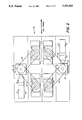
- FIG. 3 is a sectional front view of the actuating means of FIG. 2;
- FIG. 4 is a top plan view of a portion of the track assembly in combination with the actuating means of FIGS. 2 and 3;
- FIG. 5 is a top plan view of the track assembly, as illustrated in FIG. 4, in combination with a conveyor means and load station.
- the assembly 8 comprises a material handling car 10 with a chassis portion 12 movable upon a track assembly 14.
- the chassis portion 12 has fixed thereto, at either end thereof, a bumper mount 16 with two caster mounts 18 attached to each of the bumper mounts at opposite ends thereof.
- the track assembly 14 which is used in conjunction with the chassis portion 12, includes a pair of parallel opposed U-shaped rails 20 and a horizontal planar member 21, which serves as the bottom portion of the track assembly 14.
- Each of the rails 20 includes a horizontal bottom plate 22 extending inwardly from a bottom edge of a vertical side wall 24, and a horizontal top plate 26 extending inwardly from a top edge of the vertical side wall 24.
- Travel wheels 28, 30 are mounted on the caster mounts 18 of the car 10.
- the travel wheels include vertically disposed wheels 28, rotating around a horizontal axis, and horizontally disposed wheels 30, rotating around a vertical axis.
- the vertical travel wheels 28 roll upon the upper surface of the bottom rail plates 22 of the rails 20.
- the horizontal travel wheels 30 roll along the neighboring side walls 24 of the rails 20.
- the horizontal travel wheels 30 operate to keep the car 10 centered upon the track.
- the travel wheels 28 and 30 are adapted to roll on the rails 20 to facilitate movement of the car 10 along the track.
- the frame means 31 Depending from the underside of the chassis portion 12 is a frame means 31.
- the frame means 31 consists of a horizontal planar member 32, to either end of which there is attached, as by welding, the bumper mount 16 of the chassis portion 12, and L-shaped first and second frame portions 34. 36 extending downwardly toward the surface of the track horizontal member 21.
- the frame means 31 extends lengthwise of the car 10.
- the first and second frame portions 34, 36 are spaced apart from each other.
- Mounted in the track assembly 14, between the rails 20, and between the first and second frame portions 34, 36 are first and second spindles 38, 40.
- Contact wheels 42 and 44 are mounted on the spindles 38 and 40, respectively.
- the contact wheels 42, 44 are disposed in a plane normal to the spindles 38, 40, with the contact wheels 42, 44 disposed horizontally, each rotating around a vertical axis.
- engaging means 46 is fixed to the periphery of each of the contact wheels 42, 44.
- the engaging means 46 comprises elastomeric bands.
- the contact wheels 42 and 44 engage the car 10 to modify the speed of the car 10 in accordance with an actuating means 48 (FIG. 2).
- the contact wheels 42, 44 are disposed inboard of downwardly extending wall portions of first and second frame portions 34, 36. Each downwardly extending frame portion 34. 36 is engaged by one of the contact wheels 42, 44.
- Elastomeric bands, or other engaging means 46 which are placed on the peripheries of the contact wheels 42, 44, enable the contact wheels 42 and 44 to engage the frame means downwardly extending portions 34, 36.
- the elastomeric bands 46 are adapted to engage the frame portions rotationally when a car passes thereover.
- the contact wheels typically turn continuously, or when directed by a management means, engaging a car frame at a rotational speed dictated by the actuating means 48.
- the engaging means 46 of the contact wheels 42, 44 are spaced from each other, there is no continuous wear imposed upon the engaging means.
- the peripheries of the contact wheels 42, 44 will not be caused to wear down from constant rotation because the contact wheels do not engage each other, and engage the first and second downwardly extending frame portions 34, 36 only upon passage of a car thereover.
- the contact wheels 42 and 44 are disposed outboard of the frame portions 34 and 36.
- the actuating means 48 comprises the means by which the contact wheels 42, 44 are operated to modify the speed of the car 10. Each of the contact wheels 42 and 44 is operated by separate units of the actuating means 48. As shown in FIG. 2, each of the actuating means 48 comprises an operating means 50 connected to a drive wheel 52.
- the drive wheel 52 shown in FIGS. 2 and 3, is rotatably connected to at least two satellite wheels 54, 56.
- the satellite wheel 54 is in rotary connection with the contact wheel 42.
- the satellite wheel 56 is in rotary connection with the contact wheel 44.
- the operating means 50 is linearly connected to the drive wheel 52.
- the operating means 50 comprises rotary motors 51.
- Each of the operating means 50 preferably includes the rotary motor 51, an electromechanical clutch brake 53, and a gear reducer 55.
- the gear reducer 55 is adapted to increase the torque of elastomeric belts 58 and 60 which connect the drive wheel 52 to the satellite wheels 54, 56, and slows the speed of the drive wheel 52.
- the electromechanical clutch brake 53 enables the engagement of the clutch in order to propel the contact wheels 42, 44, or alternatively, the disengagement of the clutch to stop the contact wheels 42, 44.
- the rotary motors 51 are regulated by a computer (not shown), which establishes a rotational speed at which the drive wheel 52 revolves.
- the computer serves as a system management means which regulates the rotary motors, or other operating means 50.
- the drive wheel 52 is rotated by one of the rotary motors 51, driving through the clutch brake 53 and the reducer 55 (FIG. 2).
- the drive wheel 52 accommodates a continuous drive belt 58 which wraps around the outer periphery of the drive wheel 52 and the satellite wheel 54.
- the satellite wheel 54 is connected to the contact wheel 42 by the spindle 38.
- the drive belt 60 wraps around the outer periphery of the drive wheel 52 and the satellite wheel 56.
- the satellite wheel 56 is connected to the contact wheel 44 by the spindle 40.
- the drive belts 58 and 60 may be of an elastomeric material, enabling the drive wheel 52 to rotate the satellite wheels 54, 56, in order to modify the speed of the car 10.
- the satellite wheels 54, 56 are disposed drivingly between the drive wheel 52 and the contact wheels 42, 44. Each of the satellite wheels 54, 56 accommodates the continuous drive belt 58, 60.
- the satellite wheels 54, 56 are adapted to drive the spindles 38, 40, (shown in FIG. 3) which rotate the contact wheels 42, 44.
- the contact wheels 42, 44 are mounted on top of the drive spindles 38, 40.
- the satellite wheels 54, 56 are placed apart from the drive wheel 52 in order to limit the expansion of the flexible elastomeric drive belts 58, 60, respectively, the expansion being caused by the drive belts 58, 60 being stretched over a period of time.
- the satellite wheels 54, 56 are disposed in a horizontal plane with the drive wheel 52.
- the drive wheel 52, and the satellite wheels 54, 56 are disposed below the horizontal planar member 21 of the track assembly 14.
- the contact wheels 42, 44 are respectively driven by the drive spindles 38, 40 which are respectively controlled by the satellite wheels 54, 56 respectively rotated by the drive belts 58, 60.
- Neighboring contact wheels 62, 64 are respectively driven by drive spindles 66, 68 which are controlled by the satellite wheels rotated by drive belts 70, 72.
- the drive wheels 52 are adapted to rotate the contact wheels 42, 44 in engagement with the first car chassis frame portion 34, and the contact wheels 62, 64 in engagement with the second car chassis frame portion 36. This provides a supplemental source of power to each car chassis 12, in order to ensure mobility of the cars.
- each drive wheel 52 is adapted to operate a single satellite wheel, or, alternatively. adapted to operate more than two satellite wheels.
- the drive wheel 52 operated by the operating means 50, is adapted to drive multiple contact wheels 90 interconnected by means of drive belts 59, the drive belts 59 rotating satellite wheels (not shown) which drive the spindles (not shown) upon which the contact wheels 90 are mounted.
- a track has sharp inclines. When a car is traversing up or down a sharp incline, it is particularly necessary for the car to maintain a precise speed. In the present invention, a single motor is capable of accomplishing this function.
- one or more satellite wheels such as, for example, satellite wheels 62, 64, may be non-powered and adapted only to resist the compression force of other of the contact wheels as, for example, the wheels 42, 44.
- a first sensing means 80 is shown on the side of a track assembly 82.
- the first sensing means 80 is adapted to detect the approach of a car 10 on the track assembly 82.
- the first sensing means 80 may comprise a photocell.
- the photocell is adapted to emit a beam 84 (shown in phantom in FIG. 5) across the track assembly 82, the photocell beam being reflected by a reflector 86 on the opposite side of the track assembly 82 back to the photocell.
- a car 10 (not shown) approaches the track assembly 82 at a track portion 88, where the photocell is located, the car 10 interrupts the beam 84 emitted by the photocell.
- the interruption of the beam 84 activates a computer (not shown) which commences the rotation of one or more of the drive wheels 52 (as shown in FIGS. 2 and 3) by means of the rotary motors 50, and establishes a constant rotational speed by which the drive wheels 52 rotate the satellite wheels which rotate the contact wheels 90.
- the drive wheel, or wheels, 52 are adapted to rotate a multiplicity of the contact wheels.
- the rotational speed of the contact wheels 90 is fixedly established to be maintained at a constant selected determinate speed in the track assembly between the first sensing means 80 and a confirmation means 92.
- the first sensing means 80 is further adapted to activate a merge management means (not shown).
- One of the functions of the merge management means is to enable cars to merge, at a merge location 100, between other cars traveling on the track assembly 82 between the first sensing means 80 and a load station 120.
- the merge location 100 is at a selected distance from the first sensing means 80.
- a track assembly may have numerous merge locations 100.
- the merge management means comprises a computer (not shown) which operates to calculate the time between two consecutive cars traveling past the first sensing means 80. Since the cars are traveling at a constant speed controlled by the contact wheels 90, the computer is able to calculate the distance between the two cars, based on the time between them. Each car is manufactured to be the same finite length.
- the vehicle injection means 98 may comprise a photocell.
- the photocell is adapted to emit a beam 102 (shown in phantom) across the merge location 100, the photocell being reflected by a reflector 104 on the opposite side of the merge location 100 back to the photocell.
- the interruption of the beam 102 transmits a signal to the merge management means, which indicates that a car C in the vehicle injection means 98 must be merged into the track assembly 82.
- the merge management means calculates the time t1 between car A (shown in phantom in FIG. 5). a car which has passed the first sensing means 80, and car B (shown in phantom), a subsequent car which has passed the first sensing means 80.
- the interruption of the beam 84 commences the contact wheels 90 to rotate at a constant speed between the first sensing means 80 and the confirmation means 92.
- the merge management means calculates the distance between the two cars A and B, based on the time between the cars and the velocity of the cars.
- the merge management means calculates whether there is ample space, based on the length of each car, for car C (shown in phantom) to merge into the track assembly 82 between the cars A and B. If ample space has been provided between the two consecutive cars on the track assembly 82, then the contact wheels 90, disposed at the merge location 100, will accelerate the car C into the track assembly 82 from the vehicle injection means 98. In the alternative, if there is not sufficient space for the car C to enter the track assembly 82 at the vehicle injection means 98, the contact wheels 90 will brake, and the car C will remain immobilized. The contact wheels 90 will not accelerate the car C until there is sufficient room provided in the track assembly 82.
- the car A approaches the first sensing means 80 and interrupts the beam 84.
- the management means resets the timer to zero, and the contact wheels 90 begin to rotate at a selected speed which carries a car at a corresponding selected speed, as for example, 12 feet per second.
- the car A travels for 1.5 seconds before the car B interrupts the beam 84. Therefore, the car A has traveled a distance of 18 feet from the first sensing means 80.
- the car C has approached the vehicle injection means 98 and interrupted the beam 102 which activates the merge management means.
- the merge management means then instantaneously calculates whether sufficient space is provided for the car C to merge into the track assembly 82.
- the merge management means has already been given the information that the merge location 100 is 30 feet from the first sensing means 80, that each car is 6 feet long, and that it takes a car one second (12 feet) to accelerate into the track assembly 82 from the merge location 100.
- the merge management means then calculates that if there is 18 feet between cars A and B, then in one second, when the car C reaches the merge location 100, there is ample space for the car C to merge into the track assembly 82. Therefore, the contact wheels 90 accelerate the car C one second after the car B has interrupted the beam 84, and continues to accelerate for one second to merge the car C between the cars A and B in the track assembly 82.
- the contact wheels 90 brake and the car C remains immobilized until the merge management means calculates at least 18 feet between two consecutive cars.
- the contact wheels 90 accelerate the car C and merge the car C into the track assembly 82, behind the car A.
- a conveyor means 106 is disposed adjacent the track assembly 82.
- the conveyor means 106 includes a series of individual conveyors 108, 110, 112, 114, and 116. In other embodiments, there may be different numbers of individual conveyors.
- the individual conveyors 108, 110, 112, 114, and 116 are adapted to transport material to an injection means 118 at the load station 120 disposed in the stream of the conveyor means.
- the load station 120 is located a fixed distance from the first sensing means 80.
- a material identifying means 122 is disposed upstream of the individual conveyors on the conveyor means.
- the material identifying means is adapted to identify an array printed on the material, such as baggage or packages. For example, for use of this assembly in an airport, the array will identify the owner and destination of a bag. The information is then stored in the system management means.
- the material identifying means 122 confirms the presence of material approaching the material injection means.
- the material identifying means 122 comprises a laser which reads a particular printed code on a bag, or the like. The laser then sends the information to the system management means.
- the conveyor means automatically advances each material toward the load station 120.
- the injection means comprises a photocell.
- the photocell is adapted to emit a beam, 124, across the load station 120, the photocell beam being reflected by a reflector 126 on the opposite side of the load station 120, back to the photocell. While the beam 124 of the photocell is interrupted, the first material on the injection means 118 remains halted.
- the next material advances toward the load station 120, it stops on the next individual conveyor 116 upstream of the load station.
- each material will be advanced toward the load station 120 until each of the individual conveyors 108, 110, 112, 114, and 116 disposed on the conveyor means is full.
- vehicle identifying means 128 is shown disposed along the side of the track assembly 82, between the vehicle injection means 98 and the portion of the track assembly 82 directly opposite the load station 120.
- the vehicle identifying means 128 is adapted to identify the serial number of the passing car to the system management means. This number will be the number which the management means thereafter associates with the particular car. Additionally, the vehicle identifying means 128 confirms the presence of a car approaching the load station 120.
- the vehicle identifying means 128 comprises a radio frequency transponder.
- the radio frequency transponder responds to an interrogation by an antenna, and identifies the serial number to the system management means.
- Vehicle identifying means 128 are located throughout the track system. For example, if this assembly were located in an airport, the vehicle identifying means would be dispersed throughout the airport leading from and to the numerous gates and terminals. The identification of the car enables an operator to locate the car at any point in time at any location in the airport.
- the system management means recognizes the time required for the car A to approach the material injection means 118 at the load station 120.
- the system management means commences the conveyor means 106 and causes the bag to be dropped from the load station 120 onto a tray 130 (shown in FIG. 1) disposed on the chassis 12.
- the identification of the particular bag thereafter remains associated with the serial number of the particular car.
- the bag remains on the tray 130 of the chassis 12 of the car A throughout the track until it is later unloaded at another destination.
- An operator of the system management means therefore, is able to locate any bag at any time by finding the location of the car A which, as previously discussed, passes numerous vehicle identifying means 128 throughout its passage.
- the beam 124 is uninterrupted.
- the uninterrupted beam 124 causes two reactions. First, the uninterrupted beam 124 confirms to the system management means that the bag was transferred from the bag injection means 118 to the car A. Secondly, the uninterrupted beam 124 causes the system management means to start the conveyor means 106 to move the next bag which was disposed on the adjacent upstream conveyor 116 downstream to the beam 124 of the bag injection means 118. When the bag reaches the beam 124, the interrupted beam 124 stops the bag. The remaining bags each move down one conveyor toward the load station 120.
- the confirmation means 92 is adapted to confirm to the system management means that the car A carrying the material did, in fact, leave the load station 120.
- the confirmation means 92 may be a photocell.
- the photocell is adapted to emit a beam, 94, across the track assembly 82, the photocell beam being reflected by a reflector 96 on the opposite side of the track assembly 82 back to the photocell.
Abstract
Description
Claims (30)
Priority Applications (4)
| Application Number | Priority Date | Filing Date | Title |
|---|---|---|---|
| US07/967,667 US5251563A (en) | 1992-10-28 | 1992-10-28 | Synchronous drive and braking means for material handling car |
| NO933881A NO933881L (en) | 1992-10-28 | 1993-10-27 | Drive and braking device for freight handling vehicles |
| CA002109354A CA2109354A1 (en) | 1992-10-28 | 1993-10-27 | Synchronous drive and braking means for material handling car |
| EP93203026A EP0595429A1 (en) | 1992-10-28 | 1993-10-28 | Synchronous drive and braking means for material handling car |
Applications Claiming Priority (1)
| Application Number | Priority Date | Filing Date | Title |
|---|---|---|---|
| US07/967,667 US5251563A (en) | 1992-10-28 | 1992-10-28 | Synchronous drive and braking means for material handling car |
Publications (1)
| Publication Number | Publication Date |
|---|---|
| US5251563A true US5251563A (en) | 1993-10-12 |
Family
ID=25513137
Family Applications (1)
| Application Number | Title | Priority Date | Filing Date |
|---|---|---|---|
| US07/967,667 Expired - Lifetime US5251563A (en) | 1992-10-28 | 1992-10-28 | Synchronous drive and braking means for material handling car |
Country Status (4)
| Country | Link |
|---|---|
| US (1) | US5251563A (en) |
| EP (1) | EP0595429A1 (en) |
| CA (1) | CA2109354A1 (en) |
| NO (1) | NO933881L (en) |
Cited By (15)
| Publication number | Priority date | Publication date | Assignee | Title |
|---|---|---|---|---|
| US5993308A (en) | 1996-09-20 | 1999-11-30 | Foodcraft Equipment Company | Machine for eviscerating and displaying poultry for inspection |
| US6011508A (en) * | 1997-10-31 | 2000-01-04 | Magnemotion, Inc. | Accurate position-sensing and communications for guideway operated vehicles |
| US6101952A (en) * | 1997-12-24 | 2000-08-15 | Magnemotion, Inc. | Vehicle guidance and switching via magnetic forces |
| US6186881B1 (en) | 1996-09-20 | 2001-02-13 | Foodcraft Equipment Co., Ltd. | Method and apparatus for venting/opening, eviscerating/cropping, inspecting and cleaning of poultry |
| CN1071219C (en) * | 1994-03-23 | 2001-09-19 | 因诺瓦专利有限责任公司 | System for transporting persons and/or goods |
| US6781524B1 (en) | 2000-03-17 | 2004-08-24 | Magnemotion, Inc. | Passive position-sensing and communications for vehicles on a pathway |
| US6917136B2 (en) | 2001-10-01 | 2005-07-12 | Magnemotion, Inc. | Synchronous machine design and manufacturing |
| US6983701B2 (en) | 2001-10-01 | 2006-01-10 | Magnemotion, Inc. | Suspending, guiding and propelling vehicles using magnetic forces |
| US20070017411A1 (en) * | 2003-09-29 | 2007-01-25 | Tubular Rail, Inc. | Transportation system |
| US7458454B2 (en) | 2004-05-07 | 2008-12-02 | Magnemotion, Inc. | Three-dimensional motion using single-pathway based actuators |
| US8483895B1 (en) | 2009-02-25 | 2013-07-09 | James J. Beregi | Transportation system, system components and process |
| US9346371B2 (en) | 2009-01-23 | 2016-05-24 | Magnemotion, Inc. | Transport system powered by short block linear synchronous motors |
| US9771000B2 (en) | 2009-01-23 | 2017-09-26 | Magnemotion, Inc. | Short block linear synchronous motors and switching mechanisms |
| US9802507B2 (en) | 2013-09-21 | 2017-10-31 | Magnemotion, Inc. | Linear motor transport for packaging and other uses |
| CN110077796A (en) * | 2019-05-20 | 2019-08-02 | 中交路桥华东工程有限公司 | A kind of transport of materials trolley for the non-fragment orbit on protecting wall of walking |
Citations (17)
| Publication number | Priority date | Publication date | Assignee | Title |
|---|---|---|---|---|
| US147876A (en) * | 1874-02-24 | Improvement in mechanisms for propelling railway-cars | ||
| US3114332A (en) * | 1960-05-16 | 1963-12-17 | Walt Disney Prod | Bobsled amusement ride |
| US3361083A (en) * | 1965-06-09 | 1968-01-02 | United Shoe Machinery Corp | Conveyor systems |
| US3530800A (en) * | 1967-12-15 | 1970-09-29 | Wed Enterprises Inc | Self-energizing propulsion unit for driving a vehicle |
| US3610391A (en) * | 1970-03-20 | 1971-10-05 | Btu Eng Corp | Furnace conveyor system |
| US3818838A (en) * | 1970-06-08 | 1974-06-25 | Delta Design Inc | Mechanical drive module |
| SU617612A1 (en) * | 1977-03-01 | 1978-07-30 | Институт Геотехнчиеской Механики Ан Украинской Сср | Conveyer train drive |
| US4503778A (en) * | 1982-01-22 | 1985-03-12 | Wilson Fillmore G | Transportation system |
| US4530287A (en) * | 1982-03-05 | 1985-07-23 | Stiwa-Fertigungstechnik Sticht Gesellschaft M.B.H. | Conveyor arrangement |
| US4564100A (en) * | 1983-06-23 | 1986-01-14 | Acco Babcock Inc. | Carrier conveyor system |
| US4656949A (en) * | 1985-09-04 | 1987-04-14 | Lapouyade S.A. | Device for gripping and transferring load supports or containers using synchronous endless chains with drive fingers, mounted to transversely adjustable modules |
| US4671186A (en) * | 1985-06-04 | 1987-06-09 | Kunczynski Jan K | Positive drive assembly for automatic, rail-based transportation system |
| FR2595310A1 (en) * | 1986-03-07 | 1987-09-11 | Pomagalski Sa | Transport installation having an active track in a separate lane and having passive independent vehicles |
| US4793262A (en) * | 1987-10-03 | 1988-12-27 | Middlesex General Industries, Inc. | Transport system for computer integrated manufacturing/storage and drive component therefor |
| US4867069A (en) * | 1988-04-01 | 1989-09-19 | Zygmunt Alexander Kunczynski | Transportation system drive-shoe assembly and method |
| SU1609729A1 (en) * | 1988-11-03 | 1990-11-30 | Специальное Конструкторское Бюро "Транспрогресс" | Transportation system |
| JPH03224864A (en) * | 1990-01-29 | 1991-10-03 | Nkk Corp | Driving device for passenger transport vehicle |
Family Cites Families (2)
| Publication number | Priority date | Publication date | Assignee | Title |
|---|---|---|---|---|
| DE694258C (en) * | 1938-04-01 | 1940-07-27 | Gustav Strunk | Stationary device for braking and moving conveyor wagons |
| US3530802A (en) * | 1966-12-12 | 1970-09-29 | Hendrik Johan Edens | Propulsion system for vehicles |
-
1992
- 1992-10-28 US US07/967,667 patent/US5251563A/en not_active Expired - Lifetime
-
1993
- 1993-10-27 NO NO933881A patent/NO933881L/en unknown
- 1993-10-27 CA CA002109354A patent/CA2109354A1/en not_active Abandoned
- 1993-10-28 EP EP93203026A patent/EP0595429A1/en not_active Withdrawn
Patent Citations (17)
| Publication number | Priority date | Publication date | Assignee | Title |
|---|---|---|---|---|
| US147876A (en) * | 1874-02-24 | Improvement in mechanisms for propelling railway-cars | ||
| US3114332A (en) * | 1960-05-16 | 1963-12-17 | Walt Disney Prod | Bobsled amusement ride |
| US3361083A (en) * | 1965-06-09 | 1968-01-02 | United Shoe Machinery Corp | Conveyor systems |
| US3530800A (en) * | 1967-12-15 | 1970-09-29 | Wed Enterprises Inc | Self-energizing propulsion unit for driving a vehicle |
| US3610391A (en) * | 1970-03-20 | 1971-10-05 | Btu Eng Corp | Furnace conveyor system |
| US3818838A (en) * | 1970-06-08 | 1974-06-25 | Delta Design Inc | Mechanical drive module |
| SU617612A1 (en) * | 1977-03-01 | 1978-07-30 | Институт Геотехнчиеской Механики Ан Украинской Сср | Conveyer train drive |
| US4503778A (en) * | 1982-01-22 | 1985-03-12 | Wilson Fillmore G | Transportation system |
| US4530287A (en) * | 1982-03-05 | 1985-07-23 | Stiwa-Fertigungstechnik Sticht Gesellschaft M.B.H. | Conveyor arrangement |
| US4564100A (en) * | 1983-06-23 | 1986-01-14 | Acco Babcock Inc. | Carrier conveyor system |
| US4671186A (en) * | 1985-06-04 | 1987-06-09 | Kunczynski Jan K | Positive drive assembly for automatic, rail-based transportation system |
| US4656949A (en) * | 1985-09-04 | 1987-04-14 | Lapouyade S.A. | Device for gripping and transferring load supports or containers using synchronous endless chains with drive fingers, mounted to transversely adjustable modules |
| FR2595310A1 (en) * | 1986-03-07 | 1987-09-11 | Pomagalski Sa | Transport installation having an active track in a separate lane and having passive independent vehicles |
| US4793262A (en) * | 1987-10-03 | 1988-12-27 | Middlesex General Industries, Inc. | Transport system for computer integrated manufacturing/storage and drive component therefor |
| US4867069A (en) * | 1988-04-01 | 1989-09-19 | Zygmunt Alexander Kunczynski | Transportation system drive-shoe assembly and method |
| SU1609729A1 (en) * | 1988-11-03 | 1990-11-30 | Специальное Конструкторское Бюро "Транспрогресс" | Transportation system |
| JPH03224864A (en) * | 1990-01-29 | 1991-10-03 | Nkk Corp | Driving device for passenger transport vehicle |
Cited By (21)
| Publication number | Priority date | Publication date | Assignee | Title |
|---|---|---|---|---|
| CN1071219C (en) * | 1994-03-23 | 2001-09-19 | 因诺瓦专利有限责任公司 | System for transporting persons and/or goods |
| US5993308A (en) | 1996-09-20 | 1999-11-30 | Foodcraft Equipment Company | Machine for eviscerating and displaying poultry for inspection |
| US6186881B1 (en) | 1996-09-20 | 2001-02-13 | Foodcraft Equipment Co., Ltd. | Method and apparatus for venting/opening, eviscerating/cropping, inspecting and cleaning of poultry |
| US6011508A (en) * | 1997-10-31 | 2000-01-04 | Magnemotion, Inc. | Accurate position-sensing and communications for guideway operated vehicles |
| US6101952A (en) * | 1997-12-24 | 2000-08-15 | Magnemotion, Inc. | Vehicle guidance and switching via magnetic forces |
| US6781524B1 (en) | 2000-03-17 | 2004-08-24 | Magnemotion, Inc. | Passive position-sensing and communications for vehicles on a pathway |
| US7448327B2 (en) | 2001-10-01 | 2008-11-11 | Magnemotion, Inc. | Suspending, guiding and propelling vehicles using magnetic forces |
| US7538469B2 (en) | 2001-10-01 | 2009-05-26 | Magnemotion, Inc. | Synchronous machine design and manufacturing |
| US6983701B2 (en) | 2001-10-01 | 2006-01-10 | Magnemotion, Inc. | Suspending, guiding and propelling vehicles using magnetic forces |
| US20050242675A1 (en) * | 2001-10-01 | 2005-11-03 | Magnemotion, Inc. | Synchronous machine design and manufacturing |
| US6917136B2 (en) | 2001-10-01 | 2005-07-12 | Magnemotion, Inc. | Synchronous machine design and manufacturing |
| US7490557B2 (en) * | 2003-09-29 | 2009-02-17 | Tubular Rail, Inc. | Transportation system |
| US20070017411A1 (en) * | 2003-09-29 | 2007-01-25 | Tubular Rail, Inc. | Transportation system |
| US7458454B2 (en) | 2004-05-07 | 2008-12-02 | Magnemotion, Inc. | Three-dimensional motion using single-pathway based actuators |
| US7926644B2 (en) | 2004-05-07 | 2011-04-19 | Magnemotion, Inc. | Three-dimensional motion using single-pathway based actuators |
| US9346371B2 (en) | 2009-01-23 | 2016-05-24 | Magnemotion, Inc. | Transport system powered by short block linear synchronous motors |
| US9771000B2 (en) | 2009-01-23 | 2017-09-26 | Magnemotion, Inc. | Short block linear synchronous motors and switching mechanisms |
| US10112777B2 (en) | 2009-01-23 | 2018-10-30 | Magnemotion, Inc. | Transport system powered by short block linear synchronous motors |
| US8483895B1 (en) | 2009-02-25 | 2013-07-09 | James J. Beregi | Transportation system, system components and process |
| US9802507B2 (en) | 2013-09-21 | 2017-10-31 | Magnemotion, Inc. | Linear motor transport for packaging and other uses |
| CN110077796A (en) * | 2019-05-20 | 2019-08-02 | 中交路桥华东工程有限公司 | A kind of transport of materials trolley for the non-fragment orbit on protecting wall of walking |
Also Published As
| Publication number | Publication date |
|---|---|
| NO933881L (en) | 1994-04-29 |
| NO933881D0 (en) | 1993-10-27 |
| CA2109354A1 (en) | 1994-04-29 |
| EP0595429A1 (en) | 1994-05-04 |
Similar Documents
| Publication | Publication Date | Title |
|---|---|---|
| US5251563A (en) | Synchronous drive and braking means for material handling car | |
| US6360673B1 (en) | Trolley chassis | |
| US3561623A (en) | Article-handling system for baggage or other cargo | |
| US6659704B2 (en) | Loading bridge for air cargo loading | |
| US3650216A (en) | Railway car speed control transportation system | |
| CA2345400C (en) | Dual level tilting tray package sorting apparatus | |
| GB2297303A (en) | Carrier conveyor system | |
| US6371032B1 (en) | Trolley with passive discharge mechanism | |
| CN108569529B (en) | Conveying system and method for transporting cargo components | |
| US6116842A (en) | Transfer car for a conveyor system | |
| US5662045A (en) | Locomotive for material handling train | |
| JP2902354B2 (en) | Cargo transport trolley equipment | |
| US3045609A (en) | Trolley transfer means | |
| JPH01317881A (en) | Method for transferring door between lines to produce automobile | |
| JP2509954B2 (en) | High-speed automatic sorting device package transfer method | |
| CA2162322A1 (en) | Garage for a continous cable railway | |
| JPS63176213A (en) | Transfer device for assortment | |
| JPS6127805A (en) | Distributor/carrier | |
| JPH07271438A (en) | Automated guided vehicle system and automated guided vehicle to be used therefor | |
| CN212711022U (en) | Intelligent rail shuttling mother vehicle | |
| JPH07277409A (en) | Carrier device | |
| JP3013716U (en) | Magnetic induction carrier | |
| JPH0115568Y2 (en) | ||
| JPH06115606A (en) | Load carrying equipment | |
| JPH01317882A (en) | Transfer equipment using self-propelling body |
Legal Events
| Date | Code | Title | Description |
|---|---|---|---|
| AS | Assignment |
Owner name: BAE AUTOMATED SYSTEMS, INC., TEXAS Free format text: ASSIGNMENT OF ASSIGNORS INTEREST.;ASSIGNORS:STAEHS, JOEL L.;DIFONSO, GENE;BORTZFIELD, WILLIAM C.;REEL/FRAME:006313/0172 Effective date: 19921021 |
|
| STCF | Information on status: patent grant |
Free format text: PATENTED CASE |
|
| FPAY | Fee payment |
Year of fee payment: 4 |
|
| FEPP | Fee payment procedure |
Free format text: PAYOR NUMBER ASSIGNED (ORIGINAL EVENT CODE: ASPN); ENTITY STATUS OF PATENT OWNER: LARGE ENTITY |
|
| REFU | Refund |
Free format text: REFUND - PAYMENT OF MAINTENANCE FEE, 4TH YEAR, LARGE ENTITY (ORIGINAL EVENT CODE: R183); ENTITY STATUS OF PATENT OWNER: LARGE ENTITY |
|
| FPAY | Fee payment |
Year of fee payment: 8 |
|
| SULP | Surcharge for late payment |
Year of fee payment: 7 |
|
| AS | Assignment |
Owner name: ELITE LINE SERVICES, INC., FLORIDA Free format text: ASSIGNMENT OF ASSIGNORS INTEREST;ASSIGNOR:BAE AUTOMATED SYSTEMS, INC.;REEL/FRAME:013101/0411 Effective date: 20020607 |
|
| REMI | Maintenance fee reminder mailed | ||
| FPAY | Fee payment |
Year of fee payment: 12 |
|
| SULP | Surcharge for late payment |
Year of fee payment: 11 |