US5249469A - Pressure gauge - Google Patents
Pressure gauge Download PDFInfo
- Publication number
- US5249469A US5249469A US07/634,196 US63419691A US5249469A US 5249469 A US5249469 A US 5249469A US 63419691 A US63419691 A US 63419691A US 5249469 A US5249469 A US 5249469A
- Authority
- US
- United States
- Prior art keywords
- pressure sensor
- sensor means
- supporting plate
- pressure
- tubes
- Prior art date
- Legal status (The legal status is an assumption and is not a legal conclusion. Google has not performed a legal analysis and makes no representation as to the accuracy of the status listed.)
- Expired - Fee Related
Links
Images
Classifications
-
- G—PHYSICS
- G01—MEASURING; TESTING
- G01L—MEASURING FORCE, STRESS, TORQUE, WORK, MECHANICAL POWER, MECHANICAL EFFICIENCY, OR FLUID PRESSURE
- G01L9/00—Measuring steady of quasi-steady pressure of fluid or fluent solid material by electric or magnetic pressure-sensitive elements; Transmitting or indicating the displacement of mechanical pressure-sensitive elements, used to measure the steady or quasi-steady pressure of a fluid or fluent solid material, by electric or magnetic means
- G01L9/0041—Transmitting or indicating the displacement of flexible diaphragms
- G01L9/0072—Transmitting or indicating the displacement of flexible diaphragms using variations in capacitance
- G01L9/0075—Transmitting or indicating the displacement of flexible diaphragms using variations in capacitance using a ceramic diaphragm, e.g. alumina, fused quartz, glass
-
- G—PHYSICS
- G01—MEASURING; TESTING
- G01L—MEASURING FORCE, STRESS, TORQUE, WORK, MECHANICAL POWER, MECHANICAL EFFICIENCY, OR FLUID PRESSURE
- G01L19/00—Details of, or accessories for, apparatus for measuring steady or quasi-steady pressure of a fluent medium insofar as such details or accessories are not special to particular types of pressure gauges
- G01L19/14—Housings
-
- G—PHYSICS
- G01—MEASURING; TESTING
- G01L—MEASURING FORCE, STRESS, TORQUE, WORK, MECHANICAL POWER, MECHANICAL EFFICIENCY, OR FLUID PRESSURE
- G01L9/00—Measuring steady of quasi-steady pressure of fluid or fluent solid material by electric or magnetic pressure-sensitive elements; Transmitting or indicating the displacement of mechanical pressure-sensitive elements, used to measure the steady or quasi-steady pressure of a fluid or fluent solid material, by electric or magnetic means
- G01L9/0041—Transmitting or indicating the displacement of flexible diaphragms
- G01L9/0072—Transmitting or indicating the displacement of flexible diaphragms using variations in capacitance
Definitions
- the present invention relates to a pressure gauge comprising a hollow volume and a pressure sensing means mounted in this volume.
- the pressure sensor means has a conventional construction and comprises a substantially rigid, not flexible support plate and a flexible diaphragm attached to said support plate. Between said support plate and diaphragm is in this way formed a closed space which contains a reference pressure. The deflection of said diaphragm for different exterior pressures acting on said diaphragm is detected electrically by means of electrodes arranged on said diaphragm and/or support plate.
- the support plate and membrane may be configured as a capacitor, the capacitance of which is sensed by means of suitable electronic circuits.
- the hollow volume in which the pressure sensor means is mounted has a free gas connection to the volume where the pressure is to be measured.
- Pressure sensor means of the type indicated above are described e.g. in the Swedish patent application 8700556-7 which is available to the public and has been filed by the applicant.
- the whole of said pressure sensor means should be freely hanging or standing in the measuring volume inside the hollow volume in such a way that the pressure being measured, besides acting on said diaphragm, also acts on the whole of said pressure sensor means. No forces should influence the mechanical construction, particularly the support plate, of the pressure sensor means, which is displaced due to the relation of the measured pressure to the reference pressure inside said pressure sensor means.
- a mounting of this kind will among other things result in the fact that the values provided by said pressure sensor means are given an increased repeatability when the pressure sensor means is subjected to varying pressures.
- the freely hanging or standing pressure means should be mounted in such a way that the means attaching the pressure sensor means to the inner surface of the surrounding hollow volume has a small sectional area compared to the large, substantially flat surfaces of the pressure sensor means.
- Such an attachment of the pressure sensor means naturally has a relation to the desire mentioned under point 1. that no forces or as small forces as possible, besides the pressure to be measured, should influence the pressure sensor means. In addition a reduced temperature convection may in this way be obtained between the walls of the surrounding hollow volume and the pressure sensor means.
- the attachment means by means of which the pressure sensor means is attached inside the hollow volume should be mechanically connected partly to the pressure sensor means, partly to the interior wall of the surrounding hollow volume in such a way that the connecting joints do not comprise any type of soldering or elastomer. Only weld joints and glass joints should be allowed to be used.
- this attachment means is realized in the shape of a tube.
- this pressure gauge known in the art is not totally comparable to the type of pressure gauge to which the present application is related, since said support plate in the previously known construction has not a substantially flat shape.
- the pressure sensor means is attached to and only connected to the wall of the surrounding hollow volume by means of at least one tube, the section of which is small in relation to the area of the large surface of the support plate and the diaphragm of said pressure sensor means. This can be achieved by the fact that the connecting leads to the sensing electrodes of said pressure sensor means pass inside this tube or these tubes.
- the pressure sensor means according to the invention is made of a ceramic material or of a glass ceramic which are electrically not conducting materials.
- the diaphragm and supporting plate of said pressure sensor means are connected to each other by means of some suitable type of sintered glass joint.
- the exterior of said pressure sensor means may preferably be provided with an electrically conducting layer in order to electrically shield the interior of said pressure sensor means.
- the tube or tubes connecting said pressure sensor means to the surrounding housing of the pressing gauge further is made preferably of metal.
- These metal tubes may be welded and/or glassed to the large surface of the supporting plate and to the inner wall of the surrounding hollow volume, the sensor housing. Further, apparently these connecting tubes will in this case also act as an electrical shield of the connecting wires passing inside said tubes.
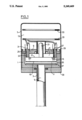
- the pressure gauge illustrated in the figure comprises a sensor housing 1, which is a cylindrical enlargement of or may be mounted on a tube conduit 3, in the interior 5 of which the pressure is present which is to be measured.
- the sensor housing is more or less hermetically closed by a cap 7 in such a way that an inner hollow volume is formed.
- the sensor housing 1 is usually made of steel and the sensor housing cap 7 may be made of steel plate or possibly plastics.
- Said inner space is divided into two volumes by an inner sensor housing cover 9 in such a way that a front volume 11 is defined. This front volume 11 is connected to the pressure to be measured and thus forms a measuring volume. Also a rear volume 13 is formed which is approximately at atmospheric pressure.
- the pressure sensor means 15 is mounted in the front volume or measurement volume.
- This is a ceramic sensor means and comprise a supporting plate having an outer surface 17 and a diaphragm having an outer surface 19 facing said tube conduit 3.
- the details of said sensor means are not illustrated on the figure since this type of pressure sensor elements are well known in the art, see for instance the Swedish patent application cited above.
- a protruding part or extension 21 may be located acting as a getter tube and also being intended for evacuation of the interior volume of said pressure sensor means.
- This interior space of said pressure sensor means is not visible in the figure but contains a determined reference pressure being for instance 1 ⁇ 10 -8 torr and usually also of the same magnitude of order as the pressure to be measured.
- the pressure sensor means 15 is connected to the sensor housing cover 9 by means of for instance two cylindrical carrying tubes 23. These are realized of a suitable metal, the thermal dilatation coefficient of which essentially coincides with the thermal dilatation coefficient of the ceramic material of said pressure sensor means 15.
- the carrying tubes are thus attached by means of glass joints to said pressure sensor means as is shown in the figure on the outer surface of the supporting plate and at the outer borders thereof and perpendicular to the surface of the supporting plate.
- the other ends of said carrying tubes 23 are inserted through bores 25 into the pressure sensor housing cover 9, this being essentially parallel to the pressure sensor means 15.
- the sensor housing cover 9 is suitably also made of the same material as the mounting elements 23.
- the sensor housing cover 9 In order to make the front volume or the measurement volume 11 quite hermetically closed in relation to the atmospheric pressure the sensor housing cover 9 also is welded to the sensor housing 1 at the outer borders thereof by means of a circumferential weld joint 29.
- the electric conductors pass towards the electrodes of the pressure sensor means 15.
- the pressure sensor means is of the capacative type and thus has electrically conducting electrodes coated both on said supporting plate and on said diaphragm, at least two electrodes of which are connected to the associated measurement electronic circuits.
- the electric wires 31 may be electrically isolated from the carrying means 23 by a medium like air, glass, sodium line glass, glass ceramics, gas or isolating paste or plastics. Usually air is preferred, however, since the electric conductors 31 are totally located in the rear volume 13 being essentially at the atmospheric pressure.
- the electric wires then pass to the electronic circuits which may be arranged on the two circuit boards 33. These circuit boards may, as is shown in the figure, be arranged in the rear region 13 of the pressure gauge which is at atmospheric pressure.
- the pressure gauge When the pressure gauge is used for measurement of the pressure of gases containing ionized particles, for instance as used for various plasma procedures, it may be convenient to protect the pressure sensor means from a direct bombardment of particles by means of a plasma shield 35 arranged in front of the diaphragm surface 19 of the pressure sensor means 15.
- the plasma shield contains recesses at its border 37 in such a way that the whole of the volume surrounding said pressure sensor means 15 has the same pressure as the interior of the tube conduit 3.
- a thermal shield 39 may be arranged around the tube 3, in which the pressure is to be measured.
- the heat shield 39 may consist of an aluminum plate and is provided with a central bore for the tube 3.
- the protecting cap 7 of the pressure sensor means is attached in such a way that the protecting cap is located at a small distance of the sensor housing 1. In this way a space containing air is obtained, surrounding the sensor housing at the outer sides thereof and improving the thermal isolation thereof.
- the measuring volume does not contain any chemically unstable components but consists of metal and a ceramical sensor element.
- the pressure sensor element can have its outer surface coated, by means of thin or thick film methods, with an electrically conducting shielding, preferably connected to the electrically conducting carrying tubes 23 and which can consist of platinum, nickel, silver platinum, silver palladium or titanic nitride.
- the sensor means is retained quite rigidly without the assistance of materials, which are essentially resilient or elastic. This will improve the repeatability of said pressure gauge at a repeated cycling of the pressure gauge in relation to for instance the atmospheric pressure. It is well known that conventional O-rings in cyclings of this kind will change when time passes on.
- the carrying means 23 have a small section in relation to the pressure sensor means 25 and in relation to the other components of the sensor housing, particularly the sensor housing plate 9, the influence of changes of the exterior temperature on the pressure sensor means 15 are reduced.
- the thermal conduction through the carrying tubes 23 is naturally small and the convection of the exterior atmosphere is limited to those small surfaces of the supporting plate surface 17, which are located inside the carrying tubes 23. This will result in the fact that the pressure sensor, regarded totally, will be relatively insensitive to occasional temperature changes.
- the carrying means 23 must not be two cylindrical tubes; they may be one or more carrying elements, e.g. only one tube located centrally or at the periphery, which may have a rectangular or square section. Further it is possible to arrange the carrying elements 23 also having their longitudinal direction essentially parallel to the surfaces of the pressure sensor means 15.
Landscapes
- Physics & Mathematics (AREA)
- General Physics & Mathematics (AREA)
- Chemical & Material Sciences (AREA)
- Engineering & Computer Science (AREA)
- Ceramic Engineering (AREA)
- Measuring Fluid Pressure (AREA)
Applications Claiming Priority (2)
| Application Number | Priority Date | Filing Date | Title |
|---|---|---|---|
| SE8801848A SE461300B (sv) | 1988-05-17 | 1988-05-17 | Tryckmaetare |
| SE8801848 | 1989-05-17 |
Publications (1)
| Publication Number | Publication Date |
|---|---|
| US5249469A true US5249469A (en) | 1993-10-05 |
Family
ID=20372349
Family Applications (1)
| Application Number | Title | Priority Date | Filing Date |
|---|---|---|---|
| US07/634,196 Expired - Fee Related US5249469A (en) | 1988-05-17 | 1989-05-17 | Pressure gauge |
Country Status (7)
| Country | Link |
|---|---|
| US (1) | US5249469A (ja) |
| EP (1) | EP0417156B1 (ja) |
| JP (1) | JPH03504277A (ja) |
| DE (1) | DE68909045D1 (ja) |
| FI (1) | FI905690A0 (ja) |
| SE (1) | SE461300B (ja) |
| WO (1) | WO1989011640A1 (ja) |
Cited By (8)
| Publication number | Priority date | Publication date | Assignee | Title |
|---|---|---|---|---|
| US6612176B2 (en) * | 2000-12-28 | 2003-09-02 | Mks Instruments, Inc. | Pressure transducer assembly with thermal shield |
| US20040187589A1 (en) * | 2003-03-22 | 2004-09-30 | Ferran Robert J. | Capacitance manometer having a relatively thick flush diaphragm under tension to provide low hysteresis |
| US6993973B2 (en) | 2003-05-16 | 2006-02-07 | Mks Instruments, Inc. | Contaminant deposition control baffle for a capacitive pressure transducer |
| US7201057B2 (en) | 2004-09-30 | 2007-04-10 | Mks Instruments, Inc. | High-temperature reduced size manometer |
| US7204150B2 (en) | 2005-01-14 | 2007-04-17 | Mks Instruments, Inc. | Turbo sump for use with capacitive pressure sensor |
| US7284439B2 (en) | 1997-12-22 | 2007-10-23 | Mks Instruments, Inc. | Method for producing a pressure sensor for detecting small pressure differences and low pressures |
| US20100014252A1 (en) * | 2007-03-19 | 2010-01-21 | Toyota Jidosha Kabushiki Kaisha | Electric unit having capacitor |
| US11561146B2 (en) * | 2017-11-08 | 2023-01-24 | Tdk Electronics Ag | Pressure sensor system having protection against freezing medium |
Families Citing this family (3)
| Publication number | Priority date | Publication date | Assignee | Title |
|---|---|---|---|---|
| US5271277A (en) * | 1991-12-23 | 1993-12-21 | The Boc Group, Inc. | Capacitance pressure transducer |
| US5902933A (en) * | 1993-02-22 | 1999-05-11 | Omron Corporation | Pressure sensor and its application |
| EP0706038B1 (en) * | 1994-10-07 | 1999-01-13 | Omron Corporation | Capacitive pressure sensor with two chambers |
Citations (16)
| Publication number | Priority date | Publication date | Assignee | Title |
|---|---|---|---|---|
| US2714703A (en) * | 1954-10-26 | 1955-08-02 | Avieu Knickerbocker Inc | Transducer |
| US3619742A (en) * | 1970-05-21 | 1971-11-09 | Rosemount Eng Co Ltd | Shielded capacitance pressure sensor |
| US4168517A (en) * | 1977-11-10 | 1979-09-18 | Lee Shih Y | Capacitive pressure transducer |
| JPS56141531A (en) * | 1980-04-04 | 1981-11-05 | Toshiba Corp | Pressure transducer |
| US4358814A (en) * | 1980-10-27 | 1982-11-09 | Setra Systems, Inc. | Capacitive pressure sensor |
| JPS5826237A (ja) * | 1981-08-07 | 1983-02-16 | Mitsubishi Electric Corp | 圧力センサ |
| US4389895A (en) * | 1981-07-27 | 1983-06-28 | Rosemount Inc. | Capacitance pressure sensor |
| US4415948A (en) * | 1981-10-13 | 1983-11-15 | United Technologies Corporation | Electrostatic bonded, silicon capacitive pressure transducer |
| EP0095966A1 (en) * | 1982-05-21 | 1983-12-07 | Allied Corporation | Pressure transducer with an invariable reference capacitor |
| DE3404262A1 (de) * | 1983-03-09 | 1984-09-13 | Fuji Electric Co., Ltd., Kawasaki | Kapazitiver messfuehler |
| US4562742A (en) * | 1984-08-07 | 1986-01-07 | Bell Microcomponents, Inc. | Capacitive pressure transducer |
| US4586109A (en) * | 1985-04-01 | 1986-04-29 | Bourns Instruments, Inc. | Batch-process silicon capacitive pressure sensor |
| US4609966A (en) * | 1984-10-11 | 1986-09-02 | Vaisala Oy | Absolute pressure transducer |
| WO1988006281A1 (en) * | 1987-02-12 | 1988-08-25 | Johnsson & Billquist Development Ab | Pressure sensor |
| US4823603A (en) * | 1988-05-03 | 1989-04-25 | Vacuum General, Inc. | Capacitance manometer having stress relief for fixed electrode |
| US4875134A (en) * | 1988-01-18 | 1989-10-17 | Vaisala Oy | Pressure sensor construction and method for its fabrication |
-
1988
- 1988-05-17 SE SE8801848A patent/SE461300B/sv not_active IP Right Cessation
-
1989
- 1989-05-17 WO PCT/SE1989/000270 patent/WO1989011640A1/en active IP Right Grant
- 1989-05-17 DE DE89906212T patent/DE68909045D1/de not_active Expired - Lifetime
- 1989-05-17 JP JP1505748A patent/JPH03504277A/ja active Pending
- 1989-05-17 EP EP89906212A patent/EP0417156B1/en not_active Expired - Lifetime
- 1989-05-17 US US07/634,196 patent/US5249469A/en not_active Expired - Fee Related
-
1990
- 1990-11-16 FI FI905690A patent/FI905690A0/fi not_active Application Discontinuation
Patent Citations (17)
| Publication number | Priority date | Publication date | Assignee | Title |
|---|---|---|---|---|
| US2714703A (en) * | 1954-10-26 | 1955-08-02 | Avieu Knickerbocker Inc | Transducer |
| US3619742A (en) * | 1970-05-21 | 1971-11-09 | Rosemount Eng Co Ltd | Shielded capacitance pressure sensor |
| US4168517A (en) * | 1977-11-10 | 1979-09-18 | Lee Shih Y | Capacitive pressure transducer |
| JPS56141531A (en) * | 1980-04-04 | 1981-11-05 | Toshiba Corp | Pressure transducer |
| US4358814A (en) * | 1980-10-27 | 1982-11-09 | Setra Systems, Inc. | Capacitive pressure sensor |
| US4389895A (en) * | 1981-07-27 | 1983-06-28 | Rosemount Inc. | Capacitance pressure sensor |
| JPS5826237A (ja) * | 1981-08-07 | 1983-02-16 | Mitsubishi Electric Corp | 圧力センサ |
| US4415948A (en) * | 1981-10-13 | 1983-11-15 | United Technologies Corporation | Electrostatic bonded, silicon capacitive pressure transducer |
| EP0095966A1 (en) * | 1982-05-21 | 1983-12-07 | Allied Corporation | Pressure transducer with an invariable reference capacitor |
| DE3404262A1 (de) * | 1983-03-09 | 1984-09-13 | Fuji Electric Co., Ltd., Kawasaki | Kapazitiver messfuehler |
| US4562742A (en) * | 1984-08-07 | 1986-01-07 | Bell Microcomponents, Inc. | Capacitive pressure transducer |
| US4609966A (en) * | 1984-10-11 | 1986-09-02 | Vaisala Oy | Absolute pressure transducer |
| US4586109A (en) * | 1985-04-01 | 1986-04-29 | Bourns Instruments, Inc. | Batch-process silicon capacitive pressure sensor |
| WO1988006281A1 (en) * | 1987-02-12 | 1988-08-25 | Johnsson & Billquist Development Ab | Pressure sensor |
| US4935841A (en) * | 1987-02-12 | 1990-06-19 | Johnsson & Billquist Development Ab | Pressure sensor |
| US4875134A (en) * | 1988-01-18 | 1989-10-17 | Vaisala Oy | Pressure sensor construction and method for its fabrication |
| US4823603A (en) * | 1988-05-03 | 1989-04-25 | Vacuum General, Inc. | Capacitance manometer having stress relief for fixed electrode |
Cited By (11)
| Publication number | Priority date | Publication date | Assignee | Title |
|---|---|---|---|---|
| US7284439B2 (en) | 1997-12-22 | 2007-10-23 | Mks Instruments, Inc. | Method for producing a pressure sensor for detecting small pressure differences and low pressures |
| US7389697B2 (en) | 1997-12-22 | 2008-06-24 | Mks Instruments | Pressure sensor for detecting small pressure differences and low pressures |
| US6612176B2 (en) * | 2000-12-28 | 2003-09-02 | Mks Instruments, Inc. | Pressure transducer assembly with thermal shield |
| US20040187589A1 (en) * | 2003-03-22 | 2004-09-30 | Ferran Robert J. | Capacitance manometer having a relatively thick flush diaphragm under tension to provide low hysteresis |
| US6837112B2 (en) | 2003-03-22 | 2005-01-04 | Stec Inc. | Capacitance manometer having a relatively thick flush diaphragm under tension to provide low hysteresis |
| US6993973B2 (en) | 2003-05-16 | 2006-02-07 | Mks Instruments, Inc. | Contaminant deposition control baffle for a capacitive pressure transducer |
| US7201057B2 (en) | 2004-09-30 | 2007-04-10 | Mks Instruments, Inc. | High-temperature reduced size manometer |
| US7204150B2 (en) | 2005-01-14 | 2007-04-17 | Mks Instruments, Inc. | Turbo sump for use with capacitive pressure sensor |
| US20100014252A1 (en) * | 2007-03-19 | 2010-01-21 | Toyota Jidosha Kabushiki Kaisha | Electric unit having capacitor |
| US8102653B2 (en) * | 2007-03-19 | 2012-01-24 | Toyota Jidosha Kabushiki Kaisha | Electric unit having capacitor |
| US11561146B2 (en) * | 2017-11-08 | 2023-01-24 | Tdk Electronics Ag | Pressure sensor system having protection against freezing medium |
Also Published As
| Publication number | Publication date |
|---|---|
| WO1989011640A1 (en) | 1989-11-30 |
| SE461300B (sv) | 1990-01-29 |
| SE8801848D0 (sv) | 1988-05-18 |
| JPH03504277A (ja) | 1991-09-19 |
| FI905690A0 (fi) | 1990-11-16 |
| EP0417156A1 (en) | 1991-03-20 |
| EP0417156B1 (en) | 1993-09-08 |
| DE68909045D1 (en) | 1993-10-14 |
| SE8801848L (sv) | 1989-11-18 |
Similar Documents
| Publication | Publication Date | Title |
|---|---|---|
| US5939639A (en) | Pressure transducer housing with barometric pressure isolation | |
| US5757608A (en) | Compensated pressure transducer | |
| JP3423686B2 (ja) | 圧力測定装置 | |
| JP2724419B2 (ja) | 圧力センサ | |
| JPS63501380A (ja) | 2重ダイヤフラム式差圧型変換器 | |
| EP0126989B2 (en) | Fluid pressure transmitter | |
| US5492016A (en) | Capacitive melt pressure measurement with center-mounted electrode post | |
| US5974893A (en) | Combined pressure responsive transducer and temperature sensor apparatus | |
| US5249469A (en) | Pressure gauge | |
| TWI306503B (en) | Pressure sensor device and method | |
| JP3431606B2 (ja) | 圧力センサ | |
| US5209121A (en) | Pressure sensor | |
| US4774626A (en) | Pressure sensor with improved capacitive pressure transducer | |
| US20050056097A1 (en) | Pressure sensor | |
| US4542435A (en) | Pressure transducer and mounting | |
| JP2001133345A (ja) | 圧力センサ | |
| JPH05264385A (ja) | 静電容量圧力変換装置及びそのセル | |
| US6058780A (en) | Capacitive pressure sensor housing having a ceramic base | |
| US11346698B2 (en) | Compact pressure and flow sensors for very high temperature and corrosive fluids | |
| JP3205325B2 (ja) | 容量性圧力センサ及び容量性差圧センサ | |
| US4536820A (en) | Electrical feedthrough means for pressure transducer | |
| US6324914B1 (en) | Pressure sensor support base with cavity | |
| US5349491A (en) | Pre-stressed pressure transducer and method of forming same | |
| US4134304A (en) | Air pressure transducer of diffusion type | |
| EP0157599B1 (en) | Pressure transducer |
Legal Events
| Date | Code | Title | Description |
|---|---|---|---|
| AS | Assignment |
Owner name: JONSSON & BILLQUIST DEVELOPMENT AB, SWEDEN Free format text: ASSIGNMENT OF ASSIGNORS INTEREST.;ASSIGNORS:JONSSON, STAFFAN;OLSSON, RAY;REEL/FRAME:005638/0520 Effective date: 19901214 |
|
| FPAY | Fee payment |
Year of fee payment: 4 |
|
| FEPP | Fee payment procedure |
Free format text: PAYOR NUMBER ASSIGNED (ORIGINAL EVENT CODE: ASPN); ENTITY STATUS OF PATENT OWNER: SMALL ENTITY |
|
| FEPP | Fee payment procedure |
Free format text: PAYOR NUMBER ASSIGNED (ORIGINAL EVENT CODE: ASPN); ENTITY STATUS OF PATENT OWNER: SMALL ENTITY Free format text: PAYER NUMBER DE-ASSIGNED (ORIGINAL EVENT CODE: RMPN); ENTITY STATUS OF PATENT OWNER: SMALL ENTITY |
|
| FPAY | Fee payment |
Year of fee payment: 8 |
|
| REMI | Maintenance fee reminder mailed | ||
| LAPS | Lapse for failure to pay maintenance fees | ||
| STCH | Information on status: patent discontinuation |
Free format text: PATENT EXPIRED DUE TO NONPAYMENT OF MAINTENANCE FEES UNDER 37 CFR 1.362 |
|
| FP | Lapsed due to failure to pay maintenance fee |
Effective date: 20051005 |