US5213339A - Pipe joint gasket - Google Patents
Pipe joint gasket Download PDFInfo
- Publication number
- US5213339A US5213339A US07/835,284 US83528492A US5213339A US 5213339 A US5213339 A US 5213339A US 83528492 A US83528492 A US 83528492A US 5213339 A US5213339 A US 5213339A
- Authority
- US
- United States
- Prior art keywords
- gasket
- inner pipe
- pipe
- annular groove
- region
- Prior art date
- Legal status (The legal status is an assumption and is not a legal conclusion. Google has not performed a legal analysis and makes no representation as to the accuracy of the status listed.)
- Expired - Lifetime
Links
- 238000007789 sealing Methods 0.000 claims abstract description 19
- 238000000034 method Methods 0.000 claims abstract description 8
- 238000003780 insertion Methods 0.000 claims description 22
- 230000037431 insertion Effects 0.000 claims description 22
- 239000000463 material Substances 0.000 claims description 8
- 229920001971 elastomer Polymers 0.000 claims description 3
- 239000000806 elastomer Substances 0.000 claims description 3
- 238000005452 bending Methods 0.000 claims 2
- 229920003023 plastic Polymers 0.000 claims 1
- 239000004033 plastic Substances 0.000 claims 1
- 230000008569 process Effects 0.000 description 5
- 230000002411 adverse Effects 0.000 description 4
- 238000009434 installation Methods 0.000 description 4
- 238000006073 displacement reaction Methods 0.000 description 3
- 235000012489 doughnuts Nutrition 0.000 description 2
- 230000009977 dual effect Effects 0.000 description 2
- XLYOFNOQVPJJNP-UHFFFAOYSA-N water Substances O XLYOFNOQVPJJNP-UHFFFAOYSA-N 0.000 description 2
- 230000008901 benefit Effects 0.000 description 1
- 239000011248 coating agent Substances 0.000 description 1
- 238000000576 coating method Methods 0.000 description 1
- 230000007547 defect Effects 0.000 description 1
- 239000000428 dust Substances 0.000 description 1
- 239000012530 fluid Substances 0.000 description 1
- 230000005012 migration Effects 0.000 description 1
- 238000013508 migration Methods 0.000 description 1
- 238000012986 modification Methods 0.000 description 1
- 230000004048 modification Effects 0.000 description 1
- 230000004044 response Effects 0.000 description 1
- 230000007480 spreading Effects 0.000 description 1
Images


Classifications
-
- F—MECHANICAL ENGINEERING; LIGHTING; HEATING; WEAPONS; BLASTING
- F16—ENGINEERING ELEMENTS AND UNITS; GENERAL MEASURES FOR PRODUCING AND MAINTAINING EFFECTIVE FUNCTIONING OF MACHINES OR INSTALLATIONS; THERMAL INSULATION IN GENERAL
- F16L—PIPES; JOINTS OR FITTINGS FOR PIPES; SUPPORTS FOR PIPES, CABLES OR PROTECTIVE TUBING; MEANS FOR THERMAL INSULATION IN GENERAL
- F16L21/00—Joints with sleeve or socket
- F16L21/02—Joints with sleeve or socket with elastic sealing rings between pipe and sleeve or between pipe and socket, e.g. with rolling or other prefabricated profiled rings
- F16L21/03—Joints with sleeve or socket with elastic sealing rings between pipe and sleeve or between pipe and socket, e.g. with rolling or other prefabricated profiled rings placed in the socket before connection
-
- F—MECHANICAL ENGINEERING; LIGHTING; HEATING; WEAPONS; BLASTING
- F16—ENGINEERING ELEMENTS AND UNITS; GENERAL MEASURES FOR PRODUCING AND MAINTAINING EFFECTIVE FUNCTIONING OF MACHINES OR INSTALLATIONS; THERMAL INSULATION IN GENERAL
- F16L—PIPES; JOINTS OR FITTINGS FOR PIPES; SUPPORTS FOR PIPES, CABLES OR PROTECTIVE TUBING; MEANS FOR THERMAL INSULATION IN GENERAL
- F16L17/00—Joints with packing adapted to sealing by fluid pressure
- F16L17/02—Joints with packing adapted to sealing by fluid pressure with sealing rings arranged between outer surface of pipe and inner surface of sleeve or socket
- F16L17/03—Joints with packing adapted to sealing by fluid pressure with sealing rings arranged between outer surface of pipe and inner surface of sleeve or socket having annular axial lips
- F16L17/035—Joints with packing adapted to sealing by fluid pressure with sealing rings arranged between outer surface of pipe and inner surface of sleeve or socket having annular axial lips the sealing rings having two lips parallel to each other
Definitions
- the present invention is a pipe joint gasket forming a seal between two cooperating pipes or vessels where one is inserted into the other.
- Pipe gaskets of similar nature to the present invention are known in the water pipe industry. Pipes of varying materials share a common need to form a seal between two cooperating pipes.
- the gaskets disclosed by prior art all have either internal or external contour or both that do not match the surfaces of the pipes that they must seal.
- Nowack teaches an air gap formed between the exterior contour of the gasket and the inside surface of the outer pipe after the joint is assembled.
- Others teach similar spaces and gaps, some of which close up during the insertion of the two cooperating pipes. The idea is apparently to make use of a point-load contact area to affect a good seal in a relatively small area at the sacrifice of other areas not establishing effective seals.
- this concept only works in controlled conditions. In practical application, uncontrolled and unfavorable pipe laying conditions are often unavoidable. Muddy trenches and under water installations, for instance, produce opportunities for the entrapment of foreign objects or materials between gasket and the outer pipe prior to the insertion of the inner pipe, and adversely affect the integrity of the seal.
- the present invention is a gasket that forms a seal between two pipes or vessels working cooperatively to make a pipe joint.
- the pipe joint comprises the gasket, an outer pipe with an annular groove to receive the gasket and an inner pipe to be inserted into the outer pipe, where the gasket is forced to fill the space between the two pipes formed by the necessary tolerances for clearance and the annular groove in the outer pipe.
- the gasket and the two, pipes share one common central longitudinal axis when centered in straight alignment.
- the gasket has generally a donut shape and is constructed from elastomeric materials with two distinct regions, a front region that is relatively rigid and less resilient, and a back region that is softer and more resilient.
- the shape of the gasket of the present invention is defined by exterior and interior contours.
- the gasket is set into the outer pipe's annular groove prior to the insertion of the inner pipe.
- the exterior contour is specifically designed to mostly resemble the curvature of the annular groove in the outer pipe.
- a portion of the external contour in the resilient back region was designed to have less curvature than the annular groove on the outer pipe, so that when the gasket is set into the outer pipe, this portion is bent and formed to conform to the shape of the annular groove. Due to its resiliency, the conformed portion of the gasket exerts pressure circumferentially on the groove, while the harder front portion forces the gasket radially outward against the pipe.
- This feature retains the gasket in the annular groove on the outer pipe and resists displacement or removal of the gasket during the insertion of the inner pipe, while at the same time employing an initial seal. Since these gaskets are often installed by pipe manufacturers, gaskets remain secure during shipment. Thus rain, dust and other foreign objects that usually find their way into the pipe joint prior to installations are kept out of pipe joint.
- the external contour also seals against minor imperfections in the pipe surfaces due to scratches, fins, porosity, coating defects, etc.
- the internal contour provides similar features providing equal sealing against similar imperfections on the inner pipe.
- the internal contour was designed so that the gasket has a smaller inside diameter in the more resilient and soft back region than in the less resilient and rigid front region. This feature keeps the inner pipe centered and prevents the inner pipe from contacting the more rigid front region of the gasket during the insertion process. Since the inner pipe never comes in contact with the rigid region during assembly, less insertion force is required to assemble the pipe joint than similar devices taught by prior art, and the tendency for the gasket to twist or dislodge is reduced making it more secure.
- the easy insertion and the tendency against migration represent significant improvements over prior art. The tendencies against twisting and dislodging are of great importance when the two cooperating pipes or vessels are not assembled in straight alignment or when they are offset relative to each other.
- the gasket After the joint is fully assembled, due to its elastomeric properties the gasket has the ability to dynamically respond to internal pipe pressure or external forces acting on the pipes while maintaining a proper seal between the two pipes or vessels.
- the resiliently conformed external and internal contours of the gasket work cooperatively inversely proportional to the forces acting on the joint to maintain the sealing ability of the gasket.
- an object of the present invention is to provide an improved gasket for connecting two cooperating pipes or vessels.
- Another object of the present invention is to provide an improved gasket that is more secure than the existing gaskets.
- Another object of the present invention is to provide an improved gasket that has a relatively rigid and resilient front region and a more resilient and soft back region.
- Another object of the present invention is to provide an improved gasket that has an external contour and an internal contour.
- Another object of the present invention is to provide an improved gasket that requires less force to insert the inner pipe into the outer pipe than existing gaskets.
- Another object of the present invention is to provide an improved gasket with external contour that has less curvature than the annular groove on the outer pipe so that after the insertion of the gasket, the resilient gasket is forced to conform to the annular grove and in turn exerts pressure on the annular groove keeping the gasket securely within the annular groove.
- Another object of the present invention is to provide an improved gasket with internal contour such that after insertion of the inner pipe the resilient gasket is forced to further conform and exerts pressure on the inner pipe keeping it securely in place.
- a further object of the present invention is to provide a gasket that seals against imperfections on the surfaces of the inner pipe and outer pipe.
- Yet a further object of the present invention is to provide a gasket that works well in adverse pipe laying conditions such as muddy trenches or submerged installations.
- Still a further object of the present invention is to provide a gasket that can dynamically respond to internal pipe pressure and external forces acting on the pipes after the pipe joint is assembled while maintaining the integrity of the seal.
- FIG. 1 is a cross-sectional view of a preferred embodiment of the present invention showing the external and internal contours, and the rigid front and the soft back regions of the preferred embodiment;
- FIG. 2 is a cross-sectional view of a typical pipe assembly comprising an outer pipe with an annular groove to receive the gasket and an inner pipe inserted into the outer pipe;
- FIG. 3 is a cross-sectional view of a gasket of the present invention superimposed onto the annular groove on the outer pipe showing a portion of the exterior contour having less curvature than the annular groove;
- FIG. 4 is a cross-sectional view of a gasket of the present invention inserted in the annular groove showing the external contour in a conformed state;
- FIG. 5 is a cross-sectional view of a gasket of the present invention inserted in the annular groove and the inner pipe in the insertion process;
- FIG. 6 is a cross-sectional view of a gasket of the present invention in a conformed state and the inner pipe in the inserted configuration;
- FIG. 7 is a cross-sectional view of a gasket of the present invention, the inner pipe and the outer pipe forming a pipe joint and the internal pressure P acting on the gasket;
- FIG. 8 is a cross-sectional view of the pipe joint with external forces P1 and P2 acting on the pipe joint;
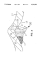
- FIG. 9 is a cross-sectional view of a gasket of the present invention inserted in the annular groove showing the distribution of the pressure exerted by the gasket on the annular groove on the outer pipe prior to insertion of the inner pipe;
- FIG. 10 is a cross-sectional view of the completed pipe joint showing the distribution of the pressure exerted by the gasket on the annular groove on the outer pipe and on the inner pipe;
- FIG. 11 is a cross-sectional view of the completed pipe joint showing the pressure distribution exerted by the gasket on the annular groove on the outer pipe and on the inner pipe with the presence of internal pressure P;
- FIG. 12 is a cross-sectional view of one of many other possible embodiments of the present invention.
- the present invention is a gasket for connecting two cooperating pipes or vessels.
- the gasket of the present invention, an inner pipe and an outer pipe with an annular groove comprise a pipe joint.
- the gasket is utilized to seal the open annulus between the inner pipe and the outer pipe, and is able to withstand internal pipe pressure and/or external forces acting on the pipes without losing integrity of the seal.
- the gasket has generally a donut shape defining an aperture with distinct exterior and interior contours.
- the gasket has a resilient and rigid front region affixed to a more resilient and soft back region. Resiliency is the capability of a strained body to recover its size and shape after deformation caused especially by compressive stress (Webster's New Collegiate Dictionary, 1976 edition, Merriam Company, Springfield, Mass.).
- the gasket is made from elastomeric materials.
- the exterior contour is designed to have less curvature than the annular groove at the end of the back region.
- the gasket When inserted into the annular groove, the gasket is bent and forced to conform to the annular groove.
- the rigid front region then forces the gasket radially outward against the pipe. Due to its resiliency, the conformed exterior surface exerts pressure on the annular groove thus keeping the gasket securely in place, and provides an initial seal against the outer pipe defending against foreign objects being displaced under the gasket prior to assembly.
- the interior contour further defines the aperture to have a smaller inside diameter at the soft back region than the inside diameter at the rigid front region.
- the inner pipe is centered by the back region, and only makes contact with this conformable soft back region and not the rigid front region thus the insertion process requires less force.
- the inner pipe displaces the interior contour radially outward into the annular groove, and forces the gasket to further conform. Again, due to its resiliency, the conformed gasket exerts pressure circumferentially around the inner pipe thus seals the annulus between the two pipes.
- the gasket When internal pressure or external forces act on the pipe joint, the gasket reacts dynamically by absorbing the internal or external load and in turn exerts more pressure on the pipe joint to preserve the integrity of the seal.
- FIG. 1 shows a cross-sectional view of gasket 30 of the present invention.
- Gasket 30 comprises rigid front region 1 and soft back region 2. Region 1 is less resilient than region 2. Gasket 30 is further defined by exterior and interior surfaces.
- the rigid front region 1 comprises tapered nose 8 and surfaces 7 and 9.
- the soft back region 2 comprises apex 15, exterior tip 3, interior tip 5, and indents 4 and 11.
- Gasket 30 of the present invention can be used to seal pipe joints similar to one shown in FIG. 2.
- Outer pipe 17 has annular groove 22 to receive gasket 30.
- Groove 22 is defined by surfaces 12 and 13.
- Surfaces 12 and 13 converge at apex 14 where outer pipe 17 has its largest diameter.
- Surface 13 has curvature matching surface 9 of front region 1.
- surface 12 has curvature not similar to the back region of gasket 30.
- Inner pipe 18 has tapered nose 20 and outer surface 21, and has an outside diameter sufficiently small to fit inside outer pipe 17.
- FIG. 3 is a superposition of gasket 30 onto annular groove 22. Exterior tip 3 has less curvature than surface 12 of annular groove 22. Thus in superposition, portion 10 of exterior tip 3 overlaps surface 12.
- FIG. 4 shows gasket 30 inserted inside annular groove 22.
- Surface 9 adjoins surface 13, and apex 15 abuts apex 14.
- Exterior tip 3 is bent about indent 4 and is forced to fit inside annular groove 22, and portion 10 presses against surface 12.
- FIG. 9 shows the general pressure profiles: F1, F2 and F3 exerted by gasket 30 circumferentially against annular groove 22.
- F1 is the pressure exerted by the hard region 1 against annular groove 22.
- F3 is the pressure exerted by the conformed portion 10 of the soft region 2 against annular groove 22
- F2 is the pressure exerted by the rest of soft region 2 against annular groove 22.
- Gasket 30 is securely set within annular groove 22, and also seals against any imperfections on the inner surface of groove 22 preventing the inclusion of foreign objects or materials between gasket 30 and groove 22 during adverse pipe laying conditions.
- FIG. 5 shows inner pipe 18 being introduced into the outer pipe 17 and gasket 30 assembly.
- Tapered nose 20 is making contact with interior tip 5.
- the aperture (not shown) defined by gasket 30 has the smallest diameter at interior tip 5.
- Inner pipe 18 is introduced into outer pipe 17 and is received by said aperture.
- FIG. 6 shows tapered nose 20 of inner pipe 18 pushed pass interior tip 5, and interior tip 5 is bent upward about indent 11.
- Interior tip 5 now completely abuts outer surface 21 of inner pipe 18 and exerts pressure on inner pipe 18.
- Gasket 30 also seals any imperfections on the outer surface of inner pipe 18. Note that the hard front region 1 is not contacting inner pipe 18.
- FIG. 10 shows another general pressure profiles exerted by gasket 30 against annular groove 22 and internal pipe 18 after the insertion of inner pipe 18.
- the magnitudes F2 and that F3 have increased with inner pipe 18 inserted to balance pressure F4 exerted by interior tip 5 against inner pipe 18.
- Pressure profile F1 remains unchanged, since hard region 1 was not displaced during the insertion process
- FIG. 7 shows internal pressure P acting on the back region 2 of gasket 30.
- Internal pressure P is present when fluid is transported through the pipe joint. Exterior tip 3 and interior tip 5 reacted dynamically by spreading away from each other to maintain intimate contacts with their respective pipe surfaces as gasket 30 is forced forward wedging hard region 1 between surface 21 of the inner pipe and surface 13 of annular groove 22. The forward movement is limited to the axial displacement of gasket 30 toward a tightly packed wedge at which point surface 7 of hard region 1 is in intimate contact with surface 21 of inner pipe 18 providing a secondary sealing area. If internal pressure P is replaced by an external pressure P' or an internal pressure vacuum (not shown), the secondary sealing area would not developed. Instead, gasket 30 will be forced inward. Exterior tip 3 and interior tip 5 would converge toward each other about indent 11 responding to the axial displacement of gasket 30, and apply more sealing pressures so as to constitute a focused sealing area in the form of converging wedge.
- FIG. 11 shows the pressure profiles exerted by gasket 30 when internal pressure P is present.
- Surface 7 of the hard region 1 contacts and exerts pressure F5 on the inner pipe 18.
- F2 and F3 increase in magnitude in response to an increase in magnitude by F4.
- F1 has also increased in magnitude to respond to the presence of F5.
- FIG. 8 shows opposite external forces Pl and P2 acting on inner pipe 18 and outer pipe 17 respectively with the tendency to dislodge the pipe joint.
- Gasket 30 would also react in a manner to counter forces P1 and P2 preserving the seal of the pipe joint.
- Gasket 30 can also react against other forces acting adversely against the pipe joint such as forces resulting from offset loading conditions, out-of-roundness of the pipes or deflected installations, etc., by responding with dynamic resilience laterally, axially and radially due to its elastomeric characteristics.
- FIG. 12 shows one of many other embodiments that encompass the features and merits of the present invention.
- FIG. 12 describes another gasket with different interior and exterior contours to be received by the outer pipe.
- Other embodiments could include the gasket being carried by the inner pipe with an inwardly projecting groove without forfeiting any of the features and merits of the present invention.
- Rigid front region 1 needs to be rigid enough to hold the gasket securely in the groove during insertion. Front region 1 can be less rigid if the groove is deep, and inversely more rigid if the groove is shallow. Thus the rigidity of the front region depends in part on the geometry of the groove. Rigid front region 1 of gasket 30 can be constructed out of elastomeric materials having a Shore A durometer of about 75 to 95. Elastomers are commonly known in the art and are widely available commercially.
- Soft back region 2 needs to be soft enough to allow easy insertion of the inside pipe into the outer pipe and to allow the interior contour of back region 2 to be easily displaced radially outward into the annular groove on the outer pipe during insertion. Soft back region 2 also needs to be soft enough to seal against imperfections on the pipe surfaces. Soft back region 2 can be constructed out of elastomers having a Shore A durometer of about 40 to 65.
Landscapes
- Engineering & Computer Science (AREA)
- General Engineering & Computer Science (AREA)
- Mechanical Engineering (AREA)
- Physics & Mathematics (AREA)
- Fluid Mechanics (AREA)
- Gasket Seals (AREA)
Abstract
Description
Claims (15)
Priority Applications (1)
| Application Number | Priority Date | Filing Date | Title |
|---|---|---|---|
| US07/835,284 US5213339A (en) | 1992-02-13 | 1992-02-13 | Pipe joint gasket |
Applications Claiming Priority (1)
| Application Number | Priority Date | Filing Date | Title |
|---|---|---|---|
| US07/835,284 US5213339A (en) | 1992-02-13 | 1992-02-13 | Pipe joint gasket |
Publications (1)
| Publication Number | Publication Date |
|---|---|
| US5213339A true US5213339A (en) | 1993-05-25 |
Family
ID=25269114
Family Applications (1)
| Application Number | Title | Priority Date | Filing Date |
|---|---|---|---|
| US07/835,284 Expired - Lifetime US5213339A (en) | 1992-02-13 | 1992-02-13 | Pipe joint gasket |
Country Status (1)
| Country | Link |
|---|---|
| US (1) | US5213339A (en) |
Cited By (36)
| Publication number | Priority date | Publication date | Assignee | Title |
|---|---|---|---|---|
| US5340125A (en) * | 1992-10-16 | 1994-08-23 | Brown Richard C | Gasket for radially spaced pipes |
| WO1995008731A1 (en) * | 1993-09-24 | 1995-03-30 | Donaldson Company, Inc. | Joint and seal system for air transfer tubes |
| NL1000584C2 (en) * | 1995-06-16 | 1996-12-19 | Wavin Bv | Pipe part with a socket end provided with a sealing assembly and sealing assembly. |
| US5662360A (en) * | 1996-01-05 | 1997-09-02 | S&B Technical Products, Inc. | Interlocked restraint for a plastic pipe joining system |
| WO1999035421A1 (en) * | 1998-01-12 | 1999-07-15 | S & B Technical Products, Inc. | Pipe gasket with improved low insertion geometry |
| US5951022A (en) * | 1997-10-06 | 1999-09-14 | Gorman Company, Inc. | Fluid seal device with reinforced dynamic lip |
| US5988695A (en) * | 1998-08-26 | 1999-11-23 | S&B Technical Products, Inc. | Pipe gasket with embedded ring |
| US5997009A (en) * | 1997-02-28 | 1999-12-07 | Formica Technology, Inc. | Single-piece seal member and method of forming a secondary seal |
| WO1999066248A1 (en) * | 1998-06-19 | 1999-12-23 | S & B Technical Products, Inc. | Pipe gasket with combined lip and compression seal geometries |
| WO2000001972A1 (en) * | 1998-07-02 | 2000-01-13 | Bidco Plastic Extrusion, Inc. | Co-extruded dual durometer hardness pipe gasket |
| US6142484A (en) * | 1999-04-15 | 2000-11-07 | Vassallo Research & Development Corporation | Composite multi-pressure gasket |
| WO2001077561A3 (en) * | 2000-04-05 | 2002-04-04 | S & B Technical Products Inc | Method of forming a pipe joint between telescoping pipe sections |
| US6499744B1 (en) * | 2000-06-05 | 2002-12-31 | S&B Technical Products, Inc. | Pipe gasket with dual purpose tail |
| US20040119285A1 (en) * | 2002-09-27 | 2004-06-24 | Foos George J. | Pipe joint and couplers |
| US20040140625A1 (en) * | 2003-01-16 | 2004-07-22 | Valls Jose E. | Socket with dual-functional composite gasket |
| US20050189408A1 (en) * | 2004-01-12 | 2005-09-01 | Corbett Bradford G.Jr. | Pipe gasket manufacturing and identification method with RFID tracking |
| US20060175765A1 (en) * | 2005-02-04 | 2006-08-10 | Happel Andrew J | Two-part gasket for pipe-to-pipe connections |
| USD556866S1 (en) * | 2006-05-22 | 2007-12-04 | S & B Technical Products, Inc. | Pipe gasket with wiper lip |
| USD557387S1 (en) * | 2007-01-11 | 2007-12-11 | S & B Technical Products, Inc. | Pipe gasket |
| USD557771S1 (en) * | 2006-10-06 | 2007-12-18 | S & B Technical Products, Inc. | Pipe gasket |
| US20080023865A1 (en) * | 2006-07-28 | 2008-01-31 | Hydril Company Lp | Revised cure cycle for annular packing units |
| US20080023917A1 (en) * | 2006-07-28 | 2008-01-31 | Hydril Company Lp | Seal for blowout preventer with selective debonding |
| US20090146419A1 (en) * | 2006-04-21 | 2009-06-11 | Trelleborg Forsheda Building Ab | Sealing Ring |
| US20090273184A1 (en) * | 2008-04-30 | 2009-11-05 | Michael Wright | Self restrained joint for ductile iron pipe and fittings |
| US9593787B2 (en) | 2013-06-21 | 2017-03-14 | S & B Technical Products, Inc. | Secured in place gasket for sealing plastic pipelines, method of manufacture and method of installation |
| JP2017082926A (en) * | 2015-10-29 | 2017-05-18 | 株式会社クボタ | Sealing material and pipe fittings |
| ES2674899A1 (en) * | 2016-12-30 | 2018-07-04 | Ismael BAJAWI CARRETERO | REINFORCED BOARD (Machine-translation by Google Translate, not legally binding) |
| US20180245727A1 (en) * | 2017-02-24 | 2018-08-30 | S & B Technical Products, Inc. | Sealing Joint for Low Pressure Pipe Systems and Method of Manufacture |
| US10107427B2 (en) | 2013-06-21 | 2018-10-23 | S & B Technical Products, Inc. | Secured in place gasket for sealing plastic pipelines, method of manufacture and method of installation |
| US10274113B2 (en) * | 2014-03-03 | 2019-04-30 | Henn Gmbh & Co Kg. | Seal |
| US10288199B2 (en) * | 2016-05-11 | 2019-05-14 | Mcwane, Inc. | Restrained plastic pipe joint and method of making same |
| US10648602B2 (en) | 2017-05-23 | 2020-05-12 | S&B Technical Products, Inc | Sealing gasket with specialized reinforcing ring for sealing plastic pipelines |
| EP3663624A1 (en) * | 2018-12-06 | 2020-06-10 | Walter Stauffenberg Gmbh & Co. Kg | Gasket |
| USD986394S1 (en) * | 2021-05-12 | 2023-05-16 | S & B Technical Products, Inc. | Pipe sealing gasket |
| JP2023174621A (en) * | 2022-05-25 | 2023-12-07 | 株式会社クボタケミックス | rubber ring socket |
| JP2023177773A (en) * | 2022-06-03 | 2023-12-14 | 株式会社ディスコ | Fixed member, fluid injection nozzle mechanism |
Citations (27)
| Publication number | Priority date | Publication date | Assignee | Title |
|---|---|---|---|---|
| US2178698A (en) * | 1936-05-04 | 1939-11-07 | Arthur J Penick | Tubing head |
| US2230725A (en) * | 1937-05-28 | 1941-02-04 | Goodrich Co B F | Sealing structure |
| US2252240A (en) * | 1939-03-16 | 1941-08-12 | Sheridan P Tschappat | Packing device |
| US2505631A (en) * | 1947-12-31 | 1950-04-25 | Webster Corp | Locking device for pipe joints |
| US2743899A (en) * | 1951-10-15 | 1956-05-01 | Wilbur C Kinney | Irrigation pipe joint with valved gasket |
| US2815973A (en) * | 1955-07-05 | 1957-12-10 | Chicksan Company | Dynamic seal |
| US2846240A (en) * | 1957-07-23 | 1958-08-05 | Walter O Beyer | Coil spring detent coupling with differentially tapered operating surfaces |
| US2916306A (en) * | 1957-01-11 | 1959-12-08 | Mcdowell Mfg Co | Pipe in socket coupling having loose thread connecting means |
| US2953398A (en) * | 1956-05-28 | 1960-09-20 | United States Pipe Foundry | Pipe joint |
| US2980449A (en) * | 1957-01-24 | 1961-04-18 | Dresser Ind | Self-sealing pipe coupling |
| US2991092A (en) * | 1957-07-05 | 1961-07-04 | American Cast Iron Pipe Co | Pipe coupling having a double sealing action gasket |
| DE1118551B (en) * | 1958-10-09 | 1961-11-30 | Halbach & Braun Maschf | Compensating pipe coupling |
| US3020054A (en) * | 1957-02-21 | 1962-02-06 | Cie De Pont A Mousson | Sealing ring for a pipe joint and the joint incorporating this ring |
| DE1129344B (en) * | 1957-07-11 | 1962-05-10 | Halberger Huette G M B H | Seal for socket pipe connections |
| GB1033756A (en) * | 1965-05-14 | 1966-06-22 | Hepworth Iron Co Ltd | Improvements in or relating to pipe couplings |
| US3315971A (en) * | 1966-05-02 | 1967-04-25 | Amsted Ind Inc | Bell and spigot joint |
| US3390890A (en) * | 1966-09-16 | 1968-07-02 | Clow Corp | Push-joint and gasket for cast pipe |
| GB1133412A (en) * | 1967-06-10 | 1968-11-13 | Hepworth Iron Co Ltd | Improvements in or relating to pipe couplings |
| GB1165663A (en) * | 1967-10-06 | 1969-10-01 | Lorowerk K H Vahlbrauk K G | A Sleeve Coupling for Tubular Members. |
| CH481342A (en) * | 1967-02-22 | 1969-11-15 | Ct De Rech S De Pont A Mousson | Connection device for tubular pipe elements |
| DE1924410A1 (en) * | 1969-05-13 | 1970-11-19 | Dueker Eisenwerk | Socket connection for pipes |
| US3698744A (en) * | 1971-01-06 | 1972-10-17 | Clow Corp | Axially locked pipe joint |
| US3856315A (en) * | 1973-01-02 | 1974-12-24 | P Stansbury | Bell and spigot pvc pipe joint |
| GB2071230A (en) * | 1980-02-26 | 1981-09-16 | Fip Formatura Inienzione Poli | Improved seal for the connections of tubes designed for the transport of fluids at variable pressures |
| US4379559A (en) * | 1979-06-29 | 1983-04-12 | Forsheda Gummifabrik Ab | Pipe sealing device |
| US4818209A (en) * | 1986-04-17 | 1989-04-04 | Forsheda Ab | Mould and sealing ring |
| US4834398A (en) * | 1987-08-31 | 1989-05-30 | S & B Technical Products, Inc. | Pipe gasket |
-
1992
- 1992-02-13 US US07/835,284 patent/US5213339A/en not_active Expired - Lifetime
Patent Citations (27)
| Publication number | Priority date | Publication date | Assignee | Title |
|---|---|---|---|---|
| US2178698A (en) * | 1936-05-04 | 1939-11-07 | Arthur J Penick | Tubing head |
| US2230725A (en) * | 1937-05-28 | 1941-02-04 | Goodrich Co B F | Sealing structure |
| US2252240A (en) * | 1939-03-16 | 1941-08-12 | Sheridan P Tschappat | Packing device |
| US2505631A (en) * | 1947-12-31 | 1950-04-25 | Webster Corp | Locking device for pipe joints |
| US2743899A (en) * | 1951-10-15 | 1956-05-01 | Wilbur C Kinney | Irrigation pipe joint with valved gasket |
| US2815973A (en) * | 1955-07-05 | 1957-12-10 | Chicksan Company | Dynamic seal |
| US2953398A (en) * | 1956-05-28 | 1960-09-20 | United States Pipe Foundry | Pipe joint |
| US2916306A (en) * | 1957-01-11 | 1959-12-08 | Mcdowell Mfg Co | Pipe in socket coupling having loose thread connecting means |
| US2980449A (en) * | 1957-01-24 | 1961-04-18 | Dresser Ind | Self-sealing pipe coupling |
| US3020054A (en) * | 1957-02-21 | 1962-02-06 | Cie De Pont A Mousson | Sealing ring for a pipe joint and the joint incorporating this ring |
| US2991092A (en) * | 1957-07-05 | 1961-07-04 | American Cast Iron Pipe Co | Pipe coupling having a double sealing action gasket |
| DE1129344B (en) * | 1957-07-11 | 1962-05-10 | Halberger Huette G M B H | Seal for socket pipe connections |
| US2846240A (en) * | 1957-07-23 | 1958-08-05 | Walter O Beyer | Coil spring detent coupling with differentially tapered operating surfaces |
| DE1118551B (en) * | 1958-10-09 | 1961-11-30 | Halbach & Braun Maschf | Compensating pipe coupling |
| GB1033756A (en) * | 1965-05-14 | 1966-06-22 | Hepworth Iron Co Ltd | Improvements in or relating to pipe couplings |
| US3315971A (en) * | 1966-05-02 | 1967-04-25 | Amsted Ind Inc | Bell and spigot joint |
| US3390890A (en) * | 1966-09-16 | 1968-07-02 | Clow Corp | Push-joint and gasket for cast pipe |
| CH481342A (en) * | 1967-02-22 | 1969-11-15 | Ct De Rech S De Pont A Mousson | Connection device for tubular pipe elements |
| GB1133412A (en) * | 1967-06-10 | 1968-11-13 | Hepworth Iron Co Ltd | Improvements in or relating to pipe couplings |
| GB1165663A (en) * | 1967-10-06 | 1969-10-01 | Lorowerk K H Vahlbrauk K G | A Sleeve Coupling for Tubular Members. |
| DE1924410A1 (en) * | 1969-05-13 | 1970-11-19 | Dueker Eisenwerk | Socket connection for pipes |
| US3698744A (en) * | 1971-01-06 | 1972-10-17 | Clow Corp | Axially locked pipe joint |
| US3856315A (en) * | 1973-01-02 | 1974-12-24 | P Stansbury | Bell and spigot pvc pipe joint |
| US4379559A (en) * | 1979-06-29 | 1983-04-12 | Forsheda Gummifabrik Ab | Pipe sealing device |
| GB2071230A (en) * | 1980-02-26 | 1981-09-16 | Fip Formatura Inienzione Poli | Improved seal for the connections of tubes designed for the transport of fluids at variable pressures |
| US4818209A (en) * | 1986-04-17 | 1989-04-04 | Forsheda Ab | Mould and sealing ring |
| US4834398A (en) * | 1987-08-31 | 1989-05-30 | S & B Technical Products, Inc. | Pipe gasket |
Cited By (54)
| Publication number | Priority date | Publication date | Assignee | Title |
|---|---|---|---|---|
| US5340125A (en) * | 1992-10-16 | 1994-08-23 | Brown Richard C | Gasket for radially spaced pipes |
| WO1995008731A1 (en) * | 1993-09-24 | 1995-03-30 | Donaldson Company, Inc. | Joint and seal system for air transfer tubes |
| US5474337A (en) * | 1993-09-24 | 1995-12-12 | Donaldson Company, Inc. | Joint and seal system for air transfer tubes |
| NL1000584C2 (en) * | 1995-06-16 | 1996-12-19 | Wavin Bv | Pipe part with a socket end provided with a sealing assembly and sealing assembly. |
| EP0748973A3 (en) * | 1995-06-16 | 1997-05-07 | Wavin Bv | Pipe part having a socket provided with a sealing assembly, and sealing assembly |
| US5662360A (en) * | 1996-01-05 | 1997-09-02 | S&B Technical Products, Inc. | Interlocked restraint for a plastic pipe joining system |
| US5997009A (en) * | 1997-02-28 | 1999-12-07 | Formica Technology, Inc. | Single-piece seal member and method of forming a secondary seal |
| US5951022A (en) * | 1997-10-06 | 1999-09-14 | Gorman Company, Inc. | Fluid seal device with reinforced dynamic lip |
| WO1999035421A1 (en) * | 1998-01-12 | 1999-07-15 | S & B Technical Products, Inc. | Pipe gasket with improved low insertion geometry |
| US6152494A (en) * | 1998-01-12 | 2000-11-28 | S&B Technical Products, Inc. | Pipe gasket with combined lip and compression seal geometries |
| US6105972A (en) * | 1998-01-12 | 2000-08-22 | S & B Technical Products, Inc. | Pipe gasket with improved low insertion geometry |
| WO1999066248A1 (en) * | 1998-06-19 | 1999-12-23 | S & B Technical Products, Inc. | Pipe gasket with combined lip and compression seal geometries |
| WO2000001972A1 (en) * | 1998-07-02 | 2000-01-13 | Bidco Plastic Extrusion, Inc. | Co-extruded dual durometer hardness pipe gasket |
| US6237966B1 (en) * | 1998-07-02 | 2001-05-29 | Bidco Plastic Extrusion, Inc. | Co-extruded dual durometer hardness pipe gasket |
| WO2000012926A1 (en) * | 1998-08-26 | 2000-03-09 | S & B Technical Products, Inc. | Pipe gasket with embedded ring |
| US5988695A (en) * | 1998-08-26 | 1999-11-23 | S&B Technical Products, Inc. | Pipe gasket with embedded ring |
| US6142484A (en) * | 1999-04-15 | 2000-11-07 | Vassallo Research & Development Corporation | Composite multi-pressure gasket |
| WO2001077561A3 (en) * | 2000-04-05 | 2002-04-04 | S & B Technical Products Inc | Method of forming a pipe joint between telescoping pipe sections |
| US6499744B1 (en) * | 2000-06-05 | 2002-12-31 | S&B Technical Products, Inc. | Pipe gasket with dual purpose tail |
| US20040119285A1 (en) * | 2002-09-27 | 2004-06-24 | Foos George J. | Pipe joint and couplers |
| US7011345B2 (en) | 2002-09-27 | 2006-03-14 | The Lamson & Sessions Co. | Pipe joint and couplers |
| US20040140625A1 (en) * | 2003-01-16 | 2004-07-22 | Valls Jose E. | Socket with dual-functional composite gasket |
| US7140618B2 (en) | 2003-01-16 | 2006-11-28 | Vassallo Research & Development Corporation | Socket with dual-functional composite gasket |
| US7158034B2 (en) * | 2004-01-12 | 2007-01-02 | Corbett Jr Bradford G | Pipe gasket manufacturing and identification method with RFID tracking |
| US20050189408A1 (en) * | 2004-01-12 | 2005-09-01 | Corbett Bradford G.Jr. | Pipe gasket manufacturing and identification method with RFID tracking |
| US7252293B2 (en) | 2005-02-04 | 2007-08-07 | Press-Seal Gasket Corporation | Two-part gasket for pipe-to-pipe connections |
| US20060175765A1 (en) * | 2005-02-04 | 2006-08-10 | Happel Andrew J | Two-part gasket for pipe-to-pipe connections |
| AU2007241584B2 (en) * | 2006-04-21 | 2013-07-18 | Trelleborg Forsheda Building Ab | Sealing ring |
| US20090146419A1 (en) * | 2006-04-21 | 2009-06-11 | Trelleborg Forsheda Building Ab | Sealing Ring |
| USD556866S1 (en) * | 2006-05-22 | 2007-12-04 | S & B Technical Products, Inc. | Pipe gasket with wiper lip |
| US20080027693A1 (en) * | 2006-07-28 | 2008-01-31 | Hydril Company Lp | Method of designing blowout preventer seal using finite element analysis |
| US20080023917A1 (en) * | 2006-07-28 | 2008-01-31 | Hydril Company Lp | Seal for blowout preventer with selective debonding |
| US8176933B2 (en) * | 2006-07-28 | 2012-05-15 | Hydril Usa Manufacturing Llc | Annular BOP packing unit |
| US20080066906A1 (en) * | 2006-07-28 | 2008-03-20 | Hydril Company Lp | Annular bop packing unit |
| US7736556B2 (en) | 2006-07-28 | 2010-06-15 | Hydril Usa Manufacturing Llc | Revised cure cycle for annular packing units |
| US20080023865A1 (en) * | 2006-07-28 | 2008-01-31 | Hydril Company Lp | Revised cure cycle for annular packing units |
| USD557771S1 (en) * | 2006-10-06 | 2007-12-18 | S & B Technical Products, Inc. | Pipe gasket |
| USD557387S1 (en) * | 2007-01-11 | 2007-12-11 | S & B Technical Products, Inc. | Pipe gasket |
| US20090273184A1 (en) * | 2008-04-30 | 2009-11-05 | Michael Wright | Self restrained joint for ductile iron pipe and fittings |
| US10107427B2 (en) | 2013-06-21 | 2018-10-23 | S & B Technical Products, Inc. | Secured in place gasket for sealing plastic pipelines, method of manufacture and method of installation |
| US9593787B2 (en) | 2013-06-21 | 2017-03-14 | S & B Technical Products, Inc. | Secured in place gasket for sealing plastic pipelines, method of manufacture and method of installation |
| US10274113B2 (en) * | 2014-03-03 | 2019-04-30 | Henn Gmbh & Co Kg. | Seal |
| JP2017082926A (en) * | 2015-10-29 | 2017-05-18 | 株式会社クボタ | Sealing material and pipe fittings |
| US10288199B2 (en) * | 2016-05-11 | 2019-05-14 | Mcwane, Inc. | Restrained plastic pipe joint and method of making same |
| ES2674899A1 (en) * | 2016-12-30 | 2018-07-04 | Ismael BAJAWI CARRETERO | REINFORCED BOARD (Machine-translation by Google Translate, not legally binding) |
| US20180245727A1 (en) * | 2017-02-24 | 2018-08-30 | S & B Technical Products, Inc. | Sealing Joint for Low Pressure Pipe Systems and Method of Manufacture |
| US10876672B2 (en) * | 2017-02-24 | 2020-12-29 | S & B Technical Products, Inc. | Sealing joint for low pressure pipe systems and method of manufacture |
| US10648602B2 (en) | 2017-05-23 | 2020-05-12 | S&B Technical Products, Inc | Sealing gasket with specialized reinforcing ring for sealing plastic pipelines |
| EP3663624A1 (en) * | 2018-12-06 | 2020-06-10 | Walter Stauffenberg Gmbh & Co. Kg | Gasket |
| USD986394S1 (en) * | 2021-05-12 | 2023-05-16 | S & B Technical Products, Inc. | Pipe sealing gasket |
| JP2023174621A (en) * | 2022-05-25 | 2023-12-07 | 株式会社クボタケミックス | rubber ring socket |
| JP2023172991A (en) * | 2022-05-25 | 2023-12-07 | 株式会社クボタケミックス | Rubber ring socket and pipe construction method |
| JP2023174620A (en) * | 2022-05-25 | 2023-12-07 | 株式会社クボタケミックス | Pipe joint |
| JP2023177773A (en) * | 2022-06-03 | 2023-12-14 | 株式会社ディスコ | Fixed member, fluid injection nozzle mechanism |
Similar Documents
| Publication | Publication Date | Title |
|---|---|---|
| US5213339A (en) | Pipe joint gasket | |
| US3020054A (en) | Sealing ring for a pipe joint and the joint incorporating this ring | |
| US4114898A (en) | Oil seal with permanently deformable locking member | |
| EP0002071B1 (en) | Synthetic resin pipe joint | |
| US5169161A (en) | Symmetrical gasket for pipe joints | |
| US5058907A (en) | Pipe joint gasket with annular anchoring heel | |
| US4834398A (en) | Pipe gasket | |
| US4379559A (en) | Pipe sealing device | |
| EP0646738B1 (en) | Fluid sealing means | |
| US4643465A (en) | Pipe coupling | |
| US3315971A (en) | Bell and spigot joint | |
| US5947533A (en) | Gasket assembly with elastomer expansion area | |
| US4258927A (en) | Shaft seal with retractable polytetrafluoroethylene-lined sealing lip | |
| US4343480A (en) | Pipe bell and gasket | |
| US4371179A (en) | T-Shaped sealing ring with elongated lip | |
| GB2177769A (en) | Improvements in or relating to hose connectors | |
| JPH0253669B2 (en) | ||
| US5029906A (en) | Method and apparatus for forming a ventable seal | |
| US3990729A (en) | End fitting for hoses | |
| EP0009368B1 (en) | Pipe coupling and pipe joint connection | |
| US3743329A (en) | Pipe coupling | |
| US20050173869A1 (en) | Spark plug tube seal | |
| EP0975906B1 (en) | Radial seal having a metal support | |
| US4572551A (en) | Fluid connector | |
| CA2427972A1 (en) | An improved seal |
Legal Events
| Date | Code | Title | Description |
|---|---|---|---|
| AS | Assignment |
Owner name: REEVES RUBBER, INC. A CORP. OF DELAWARE, ALABAMA Free format text: ASSIGNMENT OF ASSIGNORS INTEREST.;ASSIGNOR:WALWORTH, VAN T.;REEL/FRAME:006023/0027 Effective date: 19920210 |
|
| STCF | Information on status: patent grant |
Free format text: PATENTED CASE |
|
| CC | Certificate of correction | ||
| FEPP | Fee payment procedure |
Free format text: PAT HOLDER CLAIMS SMALL ENTITY STATUS - SMALL BUSINESS (ORIGINAL EVENT CODE: SM02); ENTITY STATUS OF PATENT OWNER: LARGE ENTITY |
|
| FPAY | Fee payment |
Year of fee payment: 4 |
|
| AS | Assignment |
Owner name: S&B TECHNICAL PRODUCTS, INC., TEXAS Free format text: ASSIGNMENT OF ASSIGNORS INTEREST;ASSIGNOR:REEVES RUBBER INC.;REEL/FRAME:010052/0621 Effective date: 19990617 |
|
| FEPP | Fee payment procedure |
Free format text: PAT HLDR NO LONGER CLAIMS SMALL ENT STAT AS SMALL BUSINESS (ORIGINAL EVENT CODE: LSM2); ENTITY STATUS OF PATENT OWNER: LARGE ENTITY |
|
| FPAY | Fee payment |
Year of fee payment: 8 |
|
| FPAY | Fee payment |
Year of fee payment: 12 |