EP0975906B1 - Radial seal having a metal support - Google Patents
Radial seal having a metal support Download PDFInfo
- Publication number
- EP0975906B1 EP0975906B1 EP99904509A EP99904509A EP0975906B1 EP 0975906 B1 EP0975906 B1 EP 0975906B1 EP 99904509 A EP99904509 A EP 99904509A EP 99904509 A EP99904509 A EP 99904509A EP 0975906 B1 EP0975906 B1 EP 0975906B1
- Authority
- EP
- European Patent Office
- Prior art keywords
- radial
- lip
- sealing
- seal arrangement
- shaft
- Prior art date
- Legal status (The legal status is an assumption and is not a legal conclusion. Google has not performed a legal analysis and makes no representation as to the accuracy of the status listed.)
- Expired - Lifetime
Links
Images
Classifications
-
- F—MECHANICAL ENGINEERING; LIGHTING; HEATING; WEAPONS; BLASTING
- F16—ENGINEERING ELEMENTS AND UNITS; GENERAL MEASURES FOR PRODUCING AND MAINTAINING EFFECTIVE FUNCTIONING OF MACHINES OR INSTALLATIONS; THERMAL INSULATION IN GENERAL
- F16J—PISTONS; CYLINDERS; SEALINGS
- F16J15/00—Sealings
- F16J15/16—Sealings between relatively-moving surfaces
- F16J15/32—Sealings between relatively-moving surfaces with elastic sealings, e.g. O-rings
- F16J15/3204—Sealings between relatively-moving surfaces with elastic sealings, e.g. O-rings with at least one lip
- F16J15/322—Sealings between relatively-moving surfaces with elastic sealings, e.g. O-rings with at least one lip supported in a direction perpendicular to the surfaces
-
- F—MECHANICAL ENGINEERING; LIGHTING; HEATING; WEAPONS; BLASTING
- F16—ENGINEERING ELEMENTS AND UNITS; GENERAL MEASURES FOR PRODUCING AND MAINTAINING EFFECTIVE FUNCTIONING OF MACHINES OR INSTALLATIONS; THERMAL INSULATION IN GENERAL
- F16J—PISTONS; CYLINDERS; SEALINGS
- F16J15/00—Sealings
- F16J15/16—Sealings between relatively-moving surfaces
- F16J15/32—Sealings between relatively-moving surfaces with elastic sealings, e.g. O-rings
- F16J15/3248—Sealings between relatively-moving surfaces with elastic sealings, e.g. O-rings provided with casings or supports
- F16J15/3252—Sealings between relatively-moving surfaces with elastic sealings, e.g. O-rings provided with casings or supports with rigid casings or supports
Definitions
- This invention relates generally to a radial seal for sealing a shaft (rod) and more particularly to a radial seal having first and second sealing portion and a metal support.
- Radial seals are well known in the art. These seals have many different shapes and styles to fit various applications. Many of these seals have a flexible lip extending from a body portion and require special springs and/or elastomeric members to hold the lip against the mating shaft or seal. Several of these seal designs have metal supports bonded to the elastomeric seal and are normally used to provide a member that can be pressed into a counter-bore or other types of cavities.
- One of the problems associated with these seals having metal supports is that the assembler will many times use a hammer, without a special seal driver, to press the seal into its installed position. This can result in the metal support being damaged due to the blows from the hammer.
- Some of these seals also have a second sealing surface that is spaced from the flexible lip.
- the second sealing surface needs to provide a secondary seal in the event there is some leakage in the lip seal.
- Known lip type seals having two different sealing surfaces either provide too much contact force on the surface of the installed shaft (rod) or not enough force. Too much contact force on the surface of the shaft (rod) results in a slight groove or recess being created thereon by wear between the sealing lips and the shaft (rod). Naturally, if the contact force is too small, the fluid being contained therein may leak out.
- Document GB-PS-1449 220 on which the preamble of claim 1 is based discloses a method for providing a shaft seal utilizing a sealing lip for engaging the shaft and an auxiliary lip to hinder the entry of dirt from the outside. Because of the design of the seal, a garter spring is required to apply pressure to the sealing lip to maintain a seal between the lip and the shaft. The garter spring creates additional problems because of wear and erosion, thereby requiring the cavity behind the sealing lip to be filled with an elastomeric material to prevent collapse of the seal because of internal pressures.
- the present invention is directed to overcoming one or more of the problems set forth above.
- a radial lip seal arrangement is provided as set forth in claim 1.
- Preferred embodiments of the present invention may be gathered from the dependent claims.
- a radial lip seal arrangement 10 is illustrated and disposed within a housing 11.
- the radial lip seal arrangement 10 has a reference axis 12 and includes an elastomeric member 14 and a metal support member 16.
- the metal support member 16 may be attached to the elastomeric member 14 by any conventional means such as, for example, by adhesively bonding or vulcanizing.
- the elastomeric member 14 includes a body portion 18 having a substantially linear peripheral surface 20 and a radial surface 22.
- the linear peripheral surface 20 is spaced from and extends generally parallel with the reference axis 12.
- the radial surface 22 is generally perpendicular with the reference axis 12.
- the radial surface 22 has a stepped portion 24 that extends outward from the body portion 18.
- the elastomeric member 14 also includes first and second sealing portions 26,28.
- the first sealing portion 26 includes a lip portion 30.
- the lip portion 30 extends from the body portion 18 and defines a recess 31 between the lip portion 30 and a portion of the linear peripheral surface 20.
- the lip portion 30 has a radial surface 32 that is oriented perpendicular to the reference axis 12 and an innermost surface 34 disposed thereon at an acute angle with respect to the radial surface 32.
- the second sealing portion 28 is formed by a first surface 36 extending from the perpendicular radial surface 22 of the body portion 18 and a second surface 38 that is generally perpendicular with the first surface 36.
- the second surface 38 intersects with the innermost surface 34 (third surface).
- the location of the bottom of the recess 31 is generally radially outward of the point of intersection of the second surface 38 and the innermost surface 34.
- An acute angle is formed between the perpendicular face of the radial surface 22 of the body portion 18 and the first surface 36. It is recognized that the generally perpendicular relationship between the first surface 36 and the second surface 38 would include being perpendicular or within plus or minus ten degrees from perpendicular.
- the metal support member 16 has a first leg portion 40 that extends along the linear peripheral surface 20 and a second leg portion 42 that extends along the perpendicular radial surface 22.
- the second leg portion 42 is disposed within the stepped portion of the radial surface 22 and terminates at the step.
- the termination of the second leg 42 is generally adjacent to the first surface 36 of the second sealing portion 28. This point of termination provides back-up for the second sealing portion 28.
- the housing 11 and the radial lip seal arrangement 10 are illustrated with a shaft (rod) 46 disposed through the lip seal arrangement 10 and the housing 11.
- the shaft 46 could be a slip fit within the housing 11 or have a slight clearance therebetween without departing from the essence of the subject invention.
- a lubricant is introduced or contained in the region between the housing 11 and the shaft 46 and must be sealed therein.
- the shaft 46 must be sealed at the other end or at least the cavity containing the lubricant must be closed at the opposed end.
- a lubricant is introduced into the area on the right side, as viewed in Fig. 2, of the lip seal arrangement 10.
- the lubricant can be introduced at atmospheric pressure or it can be introduced under a predetermined pressure. In either case the lip seal arrangement 10 functions to retain the lubricant therein.
- the second sealing portion 28 Upon insertion of the shaft 46, the second sealing portion 28 is forced to deform to provide the needed seal. During the deformation of the second sealing portion 28, the angle of the second surface 38 relative to the first surface 36 increases. The second sealing portion 28 not only aids in retaining the lubricant within the sealed portion its primarily acts to exclude contaminants from the sealed portion. Since the second leg 42 of the metal support member 16 provides a back-up or support behind the first surface 36, the deformation of the second sealing portion results in the angle of the second surface 38 changing. This results in the angle between the first surface 36 and the second surface 38 increasing to form a larger included angle than that prior to installing the shaft. In most arrangements this included angle would be an obtuse angle.
- the subject radial lip seal arrangement 10 provides a seal arrangement that is easy to install and has a first sealing portion 26 that maintains a minimum lubricant film between the seal lip portion 30 and the shaft 46 to resist wear and leakage. Additionally, the second leg 42 of the metal support member 16 provides support behind at least a portion of the second sealing portion 28.
Abstract
Description
- This invention relates generally to a radial seal for sealing a shaft (rod) and more particularly to a radial seal having first and second sealing portion and a metal support.
- Radial seals are well known in the art. These seals have many different shapes and styles to fit various applications. Many of these seals have a flexible lip extending from a body portion and require special springs and/or elastomeric members to hold the lip against the mating shaft or seal. Several of these seal designs have metal supports bonded to the elastomeric seal and are normally used to provide a member that can be pressed into a counter-bore or other types of cavities. One of the problems associated with these seals having metal supports is that the assembler will many times use a hammer, without a special seal driver, to press the seal into its installed position. This can result in the metal support being damaged due to the blows from the hammer. Some of these seals also have a second sealing surface that is spaced from the flexible lip. The second sealing surface needs to provide a secondary seal in the event there is some leakage in the lip seal. Known lip type seals having two different sealing surfaces (lips) either provide too much contact force on the surface of the installed shaft (rod) or not enough force. Too much contact force on the surface of the shaft (rod) results in a slight groove or recess being created thereon by wear between the sealing lips and the shaft (rod). Naturally, if the contact force is too small, the fluid being contained therein may leak out.
- Document GB-PS-1449 220 on which the preamble of claim 1 is based, discloses a method for providing a shaft seal utilizing a sealing lip for engaging the shaft and an auxiliary lip to hinder the entry of dirt from the outside. Because of the design of the seal, a garter spring is required to apply pressure to the sealing lip to maintain a seal between the lip and the shaft. The garter spring creates additional problems because of wear and erosion, thereby requiring the cavity behind the sealing lip to be filled with an elastomeric material to prevent collapse of the seal because of internal pressures.
- The present invention is directed to overcoming one or more of the problems set forth above.
- According to the present invention, a radial lip seal arrangement is provided as set forth in claim 1. Preferred embodiments of the present invention may be gathered from the dependent claims.
-
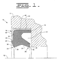
- Fig. 1 is an embodiment of the subject invention as installed in a member without a shaft or rod installed therein; and
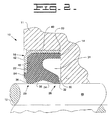
- Fig. 2 is an embodiment of the subject invention with a shaft or rod installed therein.
- Referring to the drawings and more particularly to Fig. 1, a radial
lip seal arrangement 10 is illustrated and disposed within ahousing 11. The radiallip seal arrangement 10 has areference axis 12 and includes anelastomeric member 14 and ametal support member 16. Themetal support member 16 may be attached to theelastomeric member 14 by any conventional means such as, for example, by adhesively bonding or vulcanizing. - The
elastomeric member 14 includes abody portion 18 having a substantially linearperipheral surface 20 and aradial surface 22. The linearperipheral surface 20 is spaced from and extends generally parallel with thereference axis 12. Theradial surface 22 is generally perpendicular with thereference axis 12. In the subject embodiment, theradial surface 22 has astepped portion 24 that extends outward from thebody portion 18. - The
elastomeric member 14 also includes first andsecond sealing portions first sealing portion 26 includes alip portion 30. Thelip portion 30 extends from thebody portion 18 and defines arecess 31 between thelip portion 30 and a portion of the linearperipheral surface 20. Thelip portion 30 has aradial surface 32 that is oriented perpendicular to thereference axis 12 and aninnermost surface 34 disposed thereon at an acute angle with respect to theradial surface 32. - The
second sealing portion 28 is formed by afirst surface 36 extending from the perpendicularradial surface 22 of thebody portion 18 and asecond surface 38 that is generally perpendicular with thefirst surface 36. Thesecond surface 38 intersects with the innermost surface 34 (third surface). The location of the bottom of therecess 31 is generally radially outward of the point of intersection of thesecond surface 38 and theinnermost surface 34. - An acute angle is formed between the perpendicular face of the
radial surface 22 of thebody portion 18 and thefirst surface 36. It is recognized that the generally perpendicular relationship between thefirst surface 36 and thesecond surface 38 would include being perpendicular or within plus or minus ten degrees from perpendicular. - The
metal support member 16 has afirst leg portion 40 that extends along the linearperipheral surface 20 and asecond leg portion 42 that extends along the perpendicularradial surface 22. In the subject embodiment, thesecond leg portion 42 is disposed within the stepped portion of theradial surface 22 and terminates at the step. The termination of thesecond leg 42 is generally adjacent to thefirst surface 36 of thesecond sealing portion 28. This point of termination provides back-up for thesecond sealing portion 28. By having thesecond leg 42 of themetal support member 16 disposed within thestepped portion 24, the outer surface of thesecond leg 42 is substantially aligned with the outer portion of thestepped portion 24. - Referring to Fig. 2, the
housing 11 and the radiallip seal arrangement 10 are illustrated with a shaft (rod) 46 disposed through thelip seal arrangement 10 and thehousing 11. It is recognized that theshaft 46 could be a slip fit within thehousing 11 or have a slight clearance therebetween without departing from the essence of the subject invention. In either case, a lubricant is introduced or contained in the region between thehousing 11 and theshaft 46 and must be sealed therein. It is further recognized that theshaft 46 must be sealed at the other end or at least the cavity containing the lubricant must be closed at the opposed end. - Once the
shaft 46 is placed in its installed position, a lubricant is introduced into the area on the right side, as viewed in Fig. 2, of thelip seal arrangement 10. The lubricant can be introduced at atmospheric pressure or it can be introduced under a predetermined pressure. In either case thelip seal arrangement 10 functions to retain the lubricant therein. - From a review of Fig. 2, it is apparent that the
lip portion 30 is forced to flex up, as viewed in the drawing, when theshaft 46 is installed. As thelip portion 30 is moved from its initial position, the orientation of theradial surface 32 on the lip portion changes to a position at which theradial surface 32 forms an acute angle with respect to a line perpendicular with thereference axis 12. This acute angle, following the insertion of theshaft 46, is normally within about twenty degrees. This relationship promotes sufficient force to maintain a minimum lubricant film to resist wear and prevent leakage but not enough force to cause severe damage or excess grooving to theshaft 46 which would result in leakage if the lubricant. - Upon insertion of the
shaft 46, thesecond sealing portion 28 is forced to deform to provide the needed seal. During the deformation of thesecond sealing portion 28, the angle of thesecond surface 38 relative to thefirst surface 36 increases. Thesecond sealing portion 28 not only aids in retaining the lubricant within the sealed portion its primarily acts to exclude contaminants from the sealed portion. Since thesecond leg 42 of themetal support member 16 provides a back-up or support behind thefirst surface 36, the deformation of the second sealing portion results in the angle of thesecond surface 38 changing. This results in the angle between thefirst surface 36 and thesecond surface 38 increasing to form a larger included angle than that prior to installing the shaft. In most arrangements this included angle would be an obtuse angle. - If any of the lubricant passes by the
first sealing portion 26, it is stopped and contained by thesecond sealing portion 28. - From the foregoing, it is readily apparent that the subject radial
lip seal arrangement 10 provides a seal arrangement that is easy to install and has afirst sealing portion 26 that maintains a minimum lubricant film between theseal lip portion 30 and theshaft 46 to resist wear and leakage. Additionally, thesecond leg 42 of themetal support member 16 provides support behind at least a portion of thesecond sealing portion 28. - Other aspects, objects and advantages of the invention can be obtained from a study of the drawing, the disclosure and the appended claims.
Claims (6)
- A radial lip seal arrangement (10) defining a reference axis (12) and being operative to seal the outer surface of a shaft (46) to prevent leakage of fluid therebetween, the radial lip seal arrangement (10) comprising:an elastomeric member (14) having a body portion (18) with a substantially linear peripheral surface (20) oriented generally parallel to the reference axis (12), a radial surface (22) substantially perpendicular to the reference axis (12), and first and second sealing portions (26,28) spaced from each other along a line generally parallel to the reference axis (12) of the shaft (46), the first sealing portion (26) includes a lip portion (30) extending from the body portion (18) and defines a recess between the lip portion (30) and a portion of the substantial linear peripheral surface (20), the lip portion (30) has a radial surface (32) that is generally perpendicular to the reference axis (12), the second sealing portion (28) being formed by a first surface (36) extending from the perpendicular radial surface (32) of the body portion (18) at an acute angle and a second surface (38) that is generally perpendicular to the first surface (36); anda metal support member (16) integrally attached to the body portion (18) and having a first leg portion (40) extending along the linear peripheral surface (20) of the body portion (18) and a second leg portion (42) that extends along the perpendicular radial surface (22) of the body portion (18) and terminates at a location generally adjacent to the acute angled first surface of the second sealing portion (28),characterized in that the second leg portion (42) of the metal support member (16) co-acts with the first and second sealing portions (26, 28) of the elastomeric member (14) to urge sealing contact between the first and second sealing (26, 28) and the shaft (46).
- The radial lip seal arrangement (10) of claim 1 characterized in that the acute angle of the first surface (36) of the second sealing portion (28) is less than 45 degrees.
- The radial lip seal arrangement (10) of claim 2 characterized in that a third surface (34) extends from the radial surface (22) of the lip portion (30) at an acute angle and intersects with the second surface (38) of the second sealing portion (28).
- The radial lip seal arrangement (10) of claim 3 characterized in that the recess (31) defined by the lip portion (30) terminates at a location generally radially outward from the intersection of the second and third surfaces (38,34).
- The radial lip seal arrangement (10) of claim 4 in combination with a shaft (46), characterized in that as assembled, the radial surface (32) of the lip portion (30) forms an acute angle with respect to the reference axis (12).
- The radial lip seal arrangement (10) of claim 5, characterized in that as assembled, the second surface (38) of the second sealing portion (28) forms an obtuse angle with the first surface (36) thereof.
Applications Claiming Priority (3)
| Application Number | Priority Date | Filing Date | Title |
|---|---|---|---|
| US24044 | 1998-02-16 | ||
| US09/024,044 US6045137A (en) | 1998-02-16 | 1998-02-16 | Radial seal having a metal support |
| PCT/US1999/002119 WO1999041532A1 (en) | 1998-02-16 | 1999-01-29 | Radial seal having a metal support |
Publications (2)
| Publication Number | Publication Date |
|---|---|
| EP0975906A1 EP0975906A1 (en) | 2000-02-02 |
| EP0975906B1 true EP0975906B1 (en) | 2006-12-13 |
Family
ID=21818570
Family Applications (1)
| Application Number | Title | Priority Date | Filing Date |
|---|---|---|---|
| EP99904509A Expired - Lifetime EP0975906B1 (en) | 1998-02-16 | 1999-01-29 | Radial seal having a metal support |
Country Status (5)
| Country | Link |
|---|---|
| US (1) | US6045137A (en) |
| EP (1) | EP0975906B1 (en) |
| JP (1) | JP4327264B2 (en) |
| DE (1) | DE69934361T2 (en) |
| WO (1) | WO1999041532A1 (en) |
Families Citing this family (14)
| Publication number | Priority date | Publication date | Assignee | Title |
|---|---|---|---|---|
| US6189894B1 (en) * | 1999-04-19 | 2001-02-20 | The Texacone Company | Urethane packing member with improved geometric configuration |
| US6616146B2 (en) | 2001-12-05 | 2003-09-09 | Caterpillar Inc | Radial seal arrangement |
| US6626437B2 (en) * | 2001-12-26 | 2003-09-30 | Caterpillar Inc. | Wiper seal |
| US6609716B2 (en) * | 2001-12-26 | 2003-08-26 | Caterpillar Inc | Wiper seal |
| US7134670B2 (en) * | 2003-05-29 | 2006-11-14 | Mitsubishi Cable Industries, Ltd. | Rotation shaft seal |
| US20060290068A1 (en) * | 2005-06-27 | 2006-12-28 | Freudenberg-Nok General Partnership | Radially assembled seal |
| US20090189354A1 (en) * | 2008-01-25 | 2009-07-30 | Harvey Lee L | Reciprocating-rod seal |
| US20110291366A1 (en) * | 2010-05-25 | 2011-12-01 | Jamin Micarelli | Method & Apparatus for Active Sealing and Preform Deep Drawing Composite Materials |
| EP2947307A1 (en) * | 2014-05-23 | 2015-11-25 | Aktiebolaget SKF | Cam follower roller device with integrated sealing elements, notably for a fuel injection pump |
| US10024350B2 (en) | 2016-01-20 | 2018-07-17 | Caterpillar Inc. | Seal system for dry lube pin joints |
| US10180188B2 (en) | 2016-02-10 | 2019-01-15 | Onesubsea Ip Uk Limited | Multi-material seal with lip portions |
| USD906485S1 (en) | 2017-09-27 | 2020-12-29 | Natural Gas Solutions North America, Llc | Shaft seal |
| US11339779B2 (en) | 2017-09-27 | 2022-05-24 | Natural Gas Solutions North America, Llc | Containing fluid leaks on additive pumps |
| US11555562B1 (en) * | 2021-08-30 | 2023-01-17 | Ming C Kuo | Pre-stressed concrete pipe |
Family Cites Families (22)
| Publication number | Priority date | Publication date | Assignee | Title |
|---|---|---|---|---|
| US2868566A (en) * | 1955-04-01 | 1959-01-13 | Victor Mfg & Gasket Co | Cartridge type seal for rotary shafts |
| US3106406A (en) * | 1960-06-29 | 1963-10-08 | Illinois Milling Inc | Oil seal |
| DE1425047A1 (en) * | 1963-10-23 | 1968-12-05 | Kupfer Asbest Co | Seal with bearing and guide part |
| FR1531683A (en) * | 1967-05-25 | 1968-07-05 | Paulstra Sa | Improvements made to assemblies with rotating surfaces comprising seals, in particular with ball or roller bearings |
| US3743305A (en) * | 1970-02-19 | 1973-07-03 | Federal Mogul Corp | Shaft seal with expandable outer periphery |
| AU6029173A (en) * | 1972-12-11 | 1975-03-13 | Sperry Rand Corp | Power transmission |
| US3841723A (en) * | 1973-05-22 | 1974-10-15 | Gen Motors Corp | Railway bearing seal |
| DE2427748A1 (en) * | 1974-02-14 | 1975-08-21 | Sperry Rand Corp | RING-CAPSULATED CUFF SHAFT SEAL |
| US4166628A (en) * | 1974-05-30 | 1979-09-04 | Garlock Inc. | Grease purgeable bushing seal |
| US4174845A (en) * | 1974-08-15 | 1979-11-20 | Repco Research Proprietary Limited | Fluid seal |
| US4289321A (en) * | 1979-02-27 | 1981-09-15 | Garlock Inc | Pressure shaft seal and method |
| US4465286A (en) * | 1983-02-22 | 1984-08-14 | The Bendix Corporation | Seal for closing a cavity |
| US4616836A (en) * | 1983-04-13 | 1986-10-14 | Chicago Rawhide Mfg. Co. | Reverse lip positive venting seal |
| US4537409A (en) * | 1984-03-22 | 1985-08-27 | Rock Bit Industries U.S.A., Inc. | Radial rock bit seal |
| US4789166A (en) * | 1987-09-14 | 1988-12-06 | Microdot Inc. | Rotary shaft wave seal |
| DE3739514C2 (en) * | 1987-11-21 | 1995-07-13 | Kaco Gmbh Co | Sealing ring |
| DE3806928A1 (en) * | 1988-03-03 | 1989-09-14 | Kugelfischer G Schaefer & Co | GASKET, ESPECIALLY FOR ROLLER BEARINGS |
| DE3831719B4 (en) * | 1988-09-17 | 2011-06-01 | Zf Sachs Ag | Seal for a piston rod guided axially movably in a container |
| US5482296A (en) * | 1992-09-22 | 1996-01-09 | Hallite Seals International Limited | Sealing rings and sealed assemblies |
| US5380016A (en) * | 1992-11-12 | 1995-01-10 | Caterpillar Inc. | Radial lip seal |
| US5431415A (en) * | 1993-11-15 | 1995-07-11 | Greene Tweed Of Delaware, Inc. | Seal with acute heel angle |
| DE4412132C5 (en) * | 1994-04-08 | 2005-07-28 | Ina-Schaeffler Kg | Sealing for a universal joint box |
-
1998
- 1998-02-16 US US09/024,044 patent/US6045137A/en not_active Expired - Lifetime
-
1999
- 1999-01-29 JP JP54154299A patent/JP4327264B2/en not_active Expired - Lifetime
- 1999-01-29 DE DE69934361T patent/DE69934361T2/en not_active Expired - Lifetime
- 1999-01-29 EP EP99904509A patent/EP0975906B1/en not_active Expired - Lifetime
- 1999-01-29 WO PCT/US1999/002119 patent/WO1999041532A1/en active IP Right Grant
Also Published As
| Publication number | Publication date |
|---|---|
| US6045137A (en) | 2000-04-04 |
| DE69934361D1 (en) | 2007-01-25 |
| JP4327264B2 (en) | 2009-09-09 |
| JP2001520738A (en) | 2001-10-30 |
| DE69934361T2 (en) | 2007-03-29 |
| WO1999041532A1 (en) | 1999-08-19 |
| EP0975906A1 (en) | 2000-02-02 |
Similar Documents
| Publication | Publication Date | Title |
|---|---|---|
| EP0975906B1 (en) | Radial seal having a metal support | |
| US6641141B2 (en) | Self-contained anti-blowout seal for fluids or gases | |
| US5511518A (en) | Sealing assembly with undercut groove | |
| EP0961891B1 (en) | Unidirectional rod sealing ring for a hydraulic cylinder | |
| US5056799A (en) | Lip seal device | |
| US4026563A (en) | Oil seal with locking bead and O. D. sealing rib | |
| US20190032783A1 (en) | Gasket | |
| US20020011710A1 (en) | Retrofittable severe duty seal for a shaft | |
| JP5692504B2 (en) | gasket | |
| US4114898A (en) | Oil seal with permanently deformable locking member | |
| US20080272551A1 (en) | Sealing Device | |
| US7108267B2 (en) | Seal for a shaft | |
| EP0981704B1 (en) | Shaft wiper seal | |
| JP3812621B2 (en) | End face seal | |
| US6616146B2 (en) | Radial seal arrangement | |
| EP0195682B1 (en) | Seals | |
| JP3304446B2 (en) | Packing | |
| US5678828A (en) | Sealing device | |
| JP4396820B2 (en) | Oil seal | |
| JP3197850B2 (en) | Sealing material for cylinder | |
| EP0947751A3 (en) | Fluid pressure device | |
| JPH02173475A (en) | Elastomer shaft packing for sealing of rotary shaft | |
| US20230341055A1 (en) | Seal arrangement with low drag seal gland | |
| JPH0571541U (en) | Sealing device | |
| JPH0893919A (en) | Seal part of oil pan |
Legal Events
| Date | Code | Title | Description |
|---|---|---|---|
| PUAI | Public reference made under article 153(3) epc to a published international application that has entered the european phase |
Free format text: ORIGINAL CODE: 0009012 |
|
| 17P | Request for examination filed |
Effective date: 19991013 |
|
| AK | Designated contracting states |
Kind code of ref document: A1 Designated state(s): DE FR GB IT |
|
| 17Q | First examination report despatched |
Effective date: 20030204 |
|
| GRAP | Despatch of communication of intention to grant a patent |
Free format text: ORIGINAL CODE: EPIDOSNIGR1 |
|
| GRAS | Grant fee paid |
Free format text: ORIGINAL CODE: EPIDOSNIGR3 |
|
| GRAA | (expected) grant |
Free format text: ORIGINAL CODE: 0009210 |
|
| AK | Designated contracting states |
Kind code of ref document: B1 Designated state(s): DE FR GB IT |
|
| PG25 | Lapsed in a contracting state [announced via postgrant information from national office to epo] |
Ref country code: IT Free format text: LAPSE BECAUSE OF FAILURE TO SUBMIT A TRANSLATION OF THE DESCRIPTION OR TO PAY THE FEE WITHIN THE PRESCRIBED TIME-LIMIT;WARNING: LAPSES OF ITALIAN PATENTS WITH EFFECTIVE DATE BEFORE 2007 MAY HAVE OCCURRED AT ANY TIME BEFORE 2007. THE CORRECT EFFECTIVE DATE MAY BE DIFFERENT FROM THE ONE RECORDED. Effective date: 20061213 |
|
| REG | Reference to a national code |
Ref country code: GB Ref legal event code: FG4D |
|
| REF | Corresponds to: |
Ref document number: 69934361 Country of ref document: DE Date of ref document: 20070125 Kind code of ref document: P |
|
| EN | Fr: translation not filed | ||
| PLBE | No opposition filed within time limit |
Free format text: ORIGINAL CODE: 0009261 |
|
| STAA | Information on the status of an ep patent application or granted ep patent |
Free format text: STATUS: NO OPPOSITION FILED WITHIN TIME LIMIT |
|
| 26N | No opposition filed |
Effective date: 20070914 |
|
| GBPC | Gb: european patent ceased through non-payment of renewal fee |
Effective date: 20070313 |
|
| PG25 | Lapsed in a contracting state [announced via postgrant information from national office to epo] |
Ref country code: GB Free format text: LAPSE BECAUSE OF NON-PAYMENT OF DUE FEES Effective date: 20070313 Ref country code: FR Free format text: LAPSE BECAUSE OF FAILURE TO SUBMIT A TRANSLATION OF THE DESCRIPTION OR TO PAY THE FEE WITHIN THE PRESCRIBED TIME-LIMIT Effective date: 20070803 |
|
| PG25 | Lapsed in a contracting state [announced via postgrant information from national office to epo] |
Ref country code: FR Free format text: LAPSE BECAUSE OF FAILURE TO SUBMIT A TRANSLATION OF THE DESCRIPTION OR TO PAY THE FEE WITHIN THE PRESCRIBED TIME-LIMIT Effective date: 20061213 |
|
| PGFP | Annual fee paid to national office [announced via postgrant information from national office to epo] |
Ref country code: DE Payment date: 20130131 Year of fee payment: 15 |
|
| REG | Reference to a national code |
Ref country code: DE Ref legal event code: R119 Ref document number: 69934361 Country of ref document: DE |
|
| REG | Reference to a national code |
Ref country code: DE Ref legal event code: R119 Ref document number: 69934361 Country of ref document: DE Effective date: 20140801 |
|
| PG25 | Lapsed in a contracting state [announced via postgrant information from national office to epo] |
Ref country code: DE Free format text: LAPSE BECAUSE OF NON-PAYMENT OF DUE FEES Effective date: 20140801 |