US5205206A - Food production apparatus - Google Patents
Food production apparatus Download PDFInfo
- Publication number
- US5205206A US5205206A US07/867,605 US86760592A US5205206A US 5205206 A US5205206 A US 5205206A US 86760592 A US86760592 A US 86760592A US 5205206 A US5205206 A US 5205206A
- Authority
- US
- United States
- Prior art keywords
- powder
- mixture
- storage bath
- liquid
- mixing chamber
- Prior art date
- Legal status (The legal status is an assumption and is not a legal conclusion. Google has not performed a legal analysis and makes no representation as to the accuracy of the status listed.)
- Expired - Fee Related
Links
Images


Classifications
-
- G—PHYSICS
- G07—CHECKING-DEVICES
- G07F—COIN-FREED OR LIKE APPARATUS
- G07F17/00—Coin-freed apparatus for hiring articles; Coin-freed facilities or services
- G07F17/0064—Coin-freed apparatus for hiring articles; Coin-freed facilities or services for processing of food articles
- G07F17/0078—Food articles which need to be processed for dispensing in a hot or cooked condition, e.g. popcorn, nuts
-
- A—HUMAN NECESSITIES
- A21—BAKING; EDIBLE DOUGHS
- A21C—MACHINES OR EQUIPMENT FOR MAKING OR PROCESSING DOUGHS; HANDLING BAKED ARTICLES MADE FROM DOUGH
- A21C11/00—Other machines for forming the dough into its final shape before cooking or baking
- A21C11/16—Extruding machines
-
- A—HUMAN NECESSITIES
- A23—FOODS OR FOODSTUFFS; TREATMENT THEREOF, NOT COVERED BY OTHER CLASSES
- A23L—FOODS, FOODSTUFFS, OR NON-ALCOHOLIC BEVERAGES, NOT COVERED BY SUBCLASSES A21D OR A23B-A23J; THEIR PREPARATION OR TREATMENT, e.g. COOKING, MODIFICATION OF NUTRITIVE QUALITIES, PHYSICAL TREATMENT; PRESERVATION OF FOODS OR FOODSTUFFS, IN GENERAL
- A23L19/00—Products from fruits or vegetables; Preparation or treatment thereof
- A23L19/10—Products from fruits or vegetables; Preparation or treatment thereof of tuberous or like starch containing root crops
- A23L19/12—Products from fruits or vegetables; Preparation or treatment thereof of tuberous or like starch containing root crops of potatoes
- A23L19/18—Roasted or fried products, e.g. snacks or chips
- A23L19/19—Roasted or fried products, e.g. snacks or chips from powdered or mashed potato products
-
- A—HUMAN NECESSITIES
- A23—FOODS OR FOODSTUFFS; TREATMENT THEREOF, NOT COVERED BY OTHER CLASSES
- A23P—SHAPING OR WORKING OF FOODSTUFFS, NOT FULLY COVERED BY A SINGLE OTHER SUBCLASS
- A23P30/00—Shaping or working of foodstuffs characterised by the process or apparatus
- A23P30/20—Extruding
-
- A—HUMAN NECESSITIES
- A47—FURNITURE; DOMESTIC ARTICLES OR APPLIANCES; COFFEE MILLS; SPICE MILLS; SUCTION CLEANERS IN GENERAL
- A47J—KITCHEN EQUIPMENT; COFFEE MILLS; SPICE MILLS; APPARATUS FOR MAKING BEVERAGES
- A47J37/00—Baking; Roasting; Grilling; Frying
- A47J37/12—Deep fat fryers, e.g. for frying fish or chips
- A47J37/1228—Automatic machines for frying and dispensing metered amounts of food
-
- G—PHYSICS
- G07—CHECKING-DEVICES
- G07F—COIN-FREED OR LIKE APPARATUS
- G07F9/00—Details other than those peculiar to special kinds or types of apparatus
- G07F9/10—Casings or parts thereof, e.g. with means for heating or cooling
- G07F9/105—Heating or cooling means, for temperature and humidity control, for the conditioning of articles and their storage
Definitions
- This invention relates to a food production apparatus which is preferably used in the preparation of foods such as fried potatoes.
- the invention includes extrusion shaping means in which powder obtained by pulverizing and drying potatoes or the like is provided with water and stirred, and the resulting mixture is extruded to be formed into a predetermined shape.
- an apparatus which slices potato to form slices, and fries the slices while carrying them on a conveyor, transferring the slices through a storage bath for storing edible oil which has been previously heated to a predetermined temperature.
- This prior art apparatus is constructed so as to process perishable foods such as potatoes, and therefore has a problem in that, when the apparatus is not operated for a prolonged period of time, the freshness of the potatoes is lowered, resulting in that the quality of produced foods is degraded. Since the apparatus is so constructed that slices carried on a conveyor are transferred through a storage bath, there is another problem in that the transfer path must be relatively long in order to sufficiently heat the slices, with the result that the apparatus becomes large in size.
- this prior art apparatus has a problem in that, when a small amount of a mixture is extruded, the mixture sticks to the inner surface of a casing which constitutes a mixing chamber, resulting a low yield. In contrast, when a large amount of a mixture is extruded, the extruded mixture may become rotten unless all portions of the extruded mixture is immediately further processed, e.g., fried.
- a prior art apparatus for preparing foods such as cookies using a mixture of powder, such as wheat flour, and water is independently provided with a stirring and mixing device for stirring and mixing the powder and a water, and shaping device for forming the mixture obtained by the stirring and mixing device into a predetermined shape.
- the operator carries the mixture obtained by the stirring and mixing device to supply it to the shaping device, and then collects the shaped mixture which has been extruded through extrusion holes, and thereafter the collected mixture is heated to be baked by a heating device such as an oven, which is separately installed.
- the food production apparatus of the invention is characterized in comprising a shaping device for adding water to powder supplied from a hopper to a mixing chamber, for stirring the powder and water, and for extruding the mixture of the powder and water from extrusion holes communicating with the mixing chamber to shape the mixture.
- the food production apparatus further comprises a heating device for heating the shaped mixture extruded from the shaping device.
- the food production apparatus of the invention is characterized in that the shaping device comprises a cylindrical casing including the mixing chamber, which opens downward.
- a screw conveyor is provided for transferring powder introduced from the hopper into the casing, toward the mixing chamber.
- a blade member is driven to rotate in forward and reverse directions about a rotation axis in the mixing chamber, and vertically moves along the rotation axis;
- a shutter member has a water supply unit and an extrusion unit, the water supply unit including a water supply hole for supplying water to the mixing chamber in a process of adding water, the extrusion unit being communicated with the water supply unit and provided with the extrusion holes, and the shutter member being movable between a first position in which the water supply hole opens in the mixing chamber and a second position in which the extrusion holes open in the mixing chamber.
- a driving device displaces the shutter member between the first and second positions.
- the food production apparatus of the invention is further characterized in that the heating means comprises a storage bath for storing a liquid such as water or oil.
- a temperature regulating device heats the liquid in the storage bath and maintains the temperature of the liquid at a predetermined value.
- a scooping member which is disposed in the storage bath so as to be liftable above and below the level of the liquid, has openings smaller than the mixture immersed in the liquid.
- a circular like wire net also has openings smaller than the mixture for receiving the mixture.
- a sweeping member is driven to reciprocate in predetermined directions along the upper surface of the scooping member when the scooping member is positioned at the upper limit position, higher than the level of the liquid.
- the powder accommodated in the hopper is mixed with water and then shaped, and the shaped mixture is heated by the heating device, the powder can be preserved for a long period of time. Therefore, the mixture can be shaped and heated at a desired time, and can be prepared at a desired time.
- the food production apparatus according to the invention can be advantageously used in a so-called automatic vending machine, whereby foods that have been just prepared can be supplied at a desired time.
- the apparatus since powder and water supplied into the mixing chamber of the casing are mixed by a blade member to obtain a mixture, and the mixture is extruded through the extrusion holes and shaped, the apparatus can be constructed in a reduced size, and does not require a large space for installation. Accordingly, the food production apparatus of the invention can be widely used as, for example, a so-called automatic vending machine.
- the apparatus of the invention is constructed in such a manner that the mixture is heated by a liquid which is maintained at a predetermined temperature by the temperature regulating device.
- the heated mixture is raised above the level of the liquid by the scooping member, and the heated mixture is swept out in a predetermined direction by the sweeping member. Therefore, it is not necessary to install a conveyor or the like immersed in a liquid of a storage bath, as described in conjunction with the prior art. This also enables the apparatus to be constructed in a compact size.
- the shaping device for a food material of the invention is characterized in comprising a cylindrical casing having a mixing chamber to which powder and water to be mixed are supplied.
- a bottom plate closes an opening of the casing which faces downward, the bottom plate being provided with a plurality of extrusion holes through which a mixture of the powder and water is extruded.
- a pair of shutter plates are respectively movably disposed along first and second surfaces of the bottom plate and have a plurality of through holes which can be communicated with the extrusion holes.
- the first surface faces the mixing chamber, and the second surface, being parallel with the first surface, facing toward the outside.
- a pressing member moves toward or recedes from the bottom plate in the casing, and is disposed in the casing so as to be rotatable about the shaft.
- a stirring member passes through the pressing member to project into the mixing chamber.
- powder and water are stirred in the mixing chamber to be mixed, and after the shutter plates are displaced, the mixture is extruded from the extrusion holes to be shaped. Therefore, the process of extruding and shaping the mixture can be readily and rapidly performed. Since powder and water are separately supplied, the powder can be stored for a long period of time, and the freshness of the powder can be prevented from lowering.
- the apparatus of the invention can provide a desired amount of an extruded product at a desired time. It is not necessary to additionally provide a preserving device such as a freezer, and therefore the space for installing such a device is not required, with the result that the apparatus of the invention is very simple in construction and has a remarkably increased storage capacity.
- the extrusion process is conducted, whereby the productivity of the extrusion products can be greatly improved and the mixture is maintained unexposed to the air, resulting in that dust is prevented from entering into the mixture. It is thus possible to attain a very high cleanness.
- powder and water to be mixed are supplied to the mixing chamber in the casing.
- the powder and water are stirred by the stirring member to be mixed, and then pressed by the pressing member to be extruded from the extrusion holes of the bottom plate.
- the stirring member is disposed so as to pass through the pressing member, and therefore the stirring member and the pressing member rotate during the stirring process. After the stirring process has been completed in this way, the pressing member is displaced toward the bottom plate.
- the through holes of the pair of shutter plates communicate with a plurality of extrusion holes formed in the bottom plate.
- the extrusion holes of the bottom plate are closed by the shutter plates so as to prevent the powder and water from entering into the extrusion holes when they have not yet been completely mixed with each other.
- the shutter plate disposed at the side of the second surface which faces the outside prevents the remaining portion of the mixture from dropping off.
- the remaining portion of the mixture is left in the extrusion hole for a long period of time, it becomes dried. The dried portion of the mixture sticks to the mixture which is extruded into the extrusion hole in the succeeding extrusion process.
- the food production apparatus of the invention is characterized in comprising a rotor provided with a plurality of through holes which are formed at regular intervals in the circumferential direction.
- a device intermittently drives the rotor to rotate about its rotating shaft in a predetermined direction, while stopping the rotation at each of a plurality of stopping positions which correspond to the intervals of the through holes.
- a supplying device for supplying the powder into one of the through holes is positioned at a supplying position.
- a blade member is disposed so as to be inserted into or removed from a through hole which is positioned at a mixing position which is downstream of the supplying position in the rotation direction of the rotor, the blade member being driven to rotate in forward and reverse directions while being inserted into the through hole and reciprocating upward and downward.
- a bottom plate on which the rotor is mounted is provided with a water supply hole and a communicating hole, the water supply hole opening in a through hole which is positioned at the mixing position, and the communicating hole opening in a through hole which is positioned at a shaping position, which is downstream of the mixing position in the rotation direction.
- a shaping member is detachably disposed on a lower surface of the bottom plate to close the communicating hole, and has a plurality of extrusion holes through which a mixture of powder and water stirred and mixed by the blade member at the mixing position passes.
- An extrusion member passes through a through hole positioned at the shaping position and the communicating hole and presses the mixture in the through hole, thereby extruding it from the extrusion holes.
- the rotor supported on the bottom plate is intermittently driven by the rotation-driving device.
- the rotor When powder is supplied by the supplying device to the through hole located at the supplying position of the rotor, the rotor is rotated by the rotation-driving device by an angle corresponding to the interval of the paired through holes adjacent to each other, so that the through hole to which the powder has been supplied is located at the mixing position.
- the blade member is inserted into the through hole to which the powder has been supplied and is located above the mixing position. After water is supplied to the through hole from the water supply hole formed in the bottom plate, the blade member is driven to rotate in forward and reverse directions while reciprocating upward and downward, thereby stirring and mixing the powder and water.
- the blade member is raised and retracted from the through hole, and the rotor is again rotated by the rotation-driving device so that the through hole accommodating the mixture is located at the shaping position.
- the pressing member is inserted to press the mixture, whereby the mixture is extruded from the extrusion holes of the shaping member to be formed into a shape corresponding to that of the extrusion holes.
- shaped foods can be produced in this way by a single apparatus in a series of processes including the mixing of powder and water, it is not required to construct the apparatus in a large size, and to transport and supply the mixture to another place. Therefore, foods can be produced with little labor, and the productivity can be improved.
- powder in the hopper is supplied to the mixing chamber, the mixture in the mixing chamber is provided with water and stirred, the mixture of powder and water is extruded from the extrusion holes to be shaped, and the shaped mixture is heated by the heating member, thereby producing foods.
- powder from the hopper is supplied to the casing and then transferred to the mixing chamber by the screw conveyor arranged in the casing.
- the shutter member is located at the first position, and therefore water is supplied from the water supply hole of the water supply unit to the powder in the mixing chamber.
- the blade member in the mixing chamber reciprocates upward and downward while rotating in the forward and reverse directions about the rotation axis, so that the powder and water in the mixing chamber are stirred and mixed with each other.
- the shutter member is displaced from the first position to the second position by the displacement-driving device, and the extrusion holes of the extrusion unit open in the mixing chamber.
- the screw conveyor further transfers the powder introduced from the hopper toward the mixing chamber. This causes the mixture in the mixing chamber to be extruded through the extrusion holes. In this way, by driving the screw conveyor to rotate, the mixture can be extruded through the extrusion holes to be produced into shaped foods.
- a liquid such as water or oil is stored in a storage bath, and the temperature of the liquid is maintained at a predetermined value by the temperature regulating means.
- the scooping member is disposed so as to be liftable above and below the level of the liquid. After the mixture supplied into the storage bath is heated, the scooping member is moved to the upper limit position which is higher than the level of the liquid, thereby scooping the mixture in the storage bath. Then, the sweeping member is displaced in a predetermined direction to sweep out the heated mixture on the scooping member.
- the supplying means supplies powder into the through hole of the rotor, the rotor is rotated, the blade member stirs the powder and water to mix them, and then is thus obtained mixture is extruded from the extrusion holes. Therefore, the series of processes can be conducted continuously, and it is not necessary for the operator to carry a shaped mixture to another place as described in conjunction with the prior art. This surprisingly improves the productivity, and prevents the apparatus from becoming large. Accordingly, the present apparatus does not require a large space for installation, and can be widely used as, for example, an automatic vending machine or the like.
- FIG. 1 is a sectional view illustrating the construction of an embodiment of the invention
- FIG. 2 is a diagram illustrating the embodiment of FIG. 1 in a simplified manner
- FIG. 3 is a perspective view illustrating the outer appearance of the food production apparatus of the embodiment
- FIG. 4 is a sectional view illustrating the construction of a shaping device 5;
- FIG. 5 is a sectional plan view of one portion of FIG. 4;
- FIG. 6 is a sectional view taken along section line VI--VI of FIG. 4;
- FIG. 7 is a sectional view illustrating a heating device 6
- FIG. 8 is a sectional view taken along section line VIII--VIII of FIG. 7;
- FIG. 9 is a sectional view illustrating the construction of a second embodiment of the invention.
- FIG. 10 is a sectional view illustrating an extrusion shaping device 101
- FIG. 11 is a sectional view taken along section line II--II of FIG. 10;
- FIG. 12 is a front view of the extrusion shaping device 101
- FIG. 13 is a side view of the extrusion shaping device 101 as seen from the left side in FIG. 12;
- FIG. 14 is a simplified perspective view illustrating a construction for driving an extrusion member 131 and a stirring member 132;
- FIG. 15 is a view illustrating a construction for displacing shutter plates 125 and 126 in a simplified manner
- FIGS. 16(A) and (B) are sectional views illustrating the operation of the shutter plates 125 and 126;
- FIG. 17 is a sectional view illustrating a heating device used in a third embodiment of the invention.
- FIG. 18 is a simplified perspective view illustrating a construction for driving an extrusion member 131 and a stirring member 132 used in a fourth embodiment of the invention.
- FIG. 19 is a sectional view illustrating the principle construction of a food production apparatus 201 in a fifth embodiment of the invention.
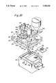
- FIG. 20 is an exploded perspective view of one portion of the food production apparatus 201.
- FIG. 21 is a sectional view taken along section line III--III of FIG. 19.
- FIG. 1 is a sectional view illustrating the whole construction of the embodiment
- FIG. 2 is a diagram illustrating the embodiment of FIG. 1
- FIG. 3 is a perspective view illustrating the outer appearance of the embodiment.
- a food production apparatus 1 principally comprises a shaping device or shaper 5 in which powder supplied from a hopper 2 to a mixing chamber 3 is provided with water and stirred and the mixture of the powder and water is shaped by extruding it through extrusion holes 4 communicating with the mixing chamber 3, and a heating device or heater 6 for heating the shaped mixture which has been extruded from the shaper 5.
- the shaper 5 and the heater 6 are accommodated in a housing 7.
- the powder may be obtained by pulverizing and drying potato or the like, or may be powder of a chicken, etc.
- the shaper 5 comprises a cylindrical casing 8 which opens downwardly.
- a screw conveyor 9 is driven to rotate at about 20 rpm so as to transfer powder introduced from a hopper 2 into the casing 8 toward the mixing chamber 3.
- a blade member 10 is driven to rotate in forward and reverse directions A1 at about 50 rpm about a rotation axis in the mixing chamber 3 and vertically moves in the direction of arrow A2 along the rotation axis.
- a shutter member 14 is made of a synthetic resin, and has a water supply unit 12 including a water supply hole 11 for supplying water to the mixing chamber 3 in a process of adding water and an extrusion unit 13 which is communicated with the water supply unit 12 and provided with the extrusion holes 4.
- a motor 15 is the driving device for driving the shutter member 14 so as to be displaced between a first position (the state shown in FIG. 1) in which the water supply hole 11 opens in the mixing chamber 3 and a second position in which the extrusion holes 4 open in the mixing chamber 3.
- a breaker 97 which is driven by a motor M9 to stir the powder in the hopper 2, may be provided.
- the heater 6 comprises a storage bath 18 for storing liquid edible oil.
- a temperature regulator 19 regulates the temperature for heating the edible oil in the storage bath 18 and maintains its temperature at a predetermined temperature, e.g., about 180° C.
- a net-like scooping member 20 is disposed in the storage bath 18 so as to be liftable above and below the level of the edible oil and has openings smaller than the mixture extruded from the extrusion holes 4.
- a sweeping member 21 displaces in a predetermined direction A3 to sweep out the mixture lifted above the level of the edible oil by the scooping member 20.
- a wire net 99 and a wire net 98 are disposed in the oil storage bath 18 which receives the mixture and has openings smaller than the mixture so that, when the mixture is lifted by the scooping member 20, the mixture does not remain in the storage bath 18.
- the housing 7 has a housing body 23 and a door 25 which is pivotably attached to the housing body 23 by a hinge 24.
- the door 25 is provided with a control panel 26 pivoted to the door 25.
- the control panel 26 is provided with a slot 27 for a coin or the like.
- a food outlet 28 is disposed on the door 25 and beneath the control panel 26.
- FIG. 4 is an enlarged sectional view illustrating the construction of the shaper 5, and FIG. 5 is a sectional plan view of one portion of FIG. 4 as viewed from above the shaper 5.
- a first gear 31 is coaxially fixed to a rotation shaft 30 of the screw conveyor 9, and a second gear 33 is fixed to a rotation shaft 32 which is movably inserted through the rotation shaft 30 in the shaft direction.
- the first gear 31 engages with a third gear 35 which is fixed to the output shaft 34 of a motor M1
- the second gear 33 engages with a fourth gear 37 which is fixed to the output shaft 36 of a motor M2.
- the blade members 10 are disposed at the lower end of the rotation shaft 32, which is movably inserted into the second gear 33 by passing through the rotation shaft 30 so as to receive only the turning force transmitted by the second gear 33.
- FIG. 6 is a sectional view taken along section line VI--VI of FIG. 4.
- the blade members 10 (the number of which is two in this embodiment) attached to the rotation shaft 32 are spaced in the shaft direction, and are constructed to perform a stirring operation as follows.
- the lower blade member 10a When rotated in the forward direction A1a while vertically moving along the shaft direction, the lower blade member 10a directs the mixture in the mixing chamber 3 toward the radially inner portion and the upper blade member 10b directs the mixture toward the radially outer portion, and when rotated in the reverse direction A1b, the lower blade member 10a directs the mixture toward the radially outer portion and the upper blade member 10b directs the mixture toward the radially inner portion.
- the water supply unit 12 of the shutter 14 is disposed under the thus constructed blade members 10. In advance of the stirring operation by the blade members 10, for example, city water is supplied from the water supply hole 11.
- a motor M3 is energized to rotate a pinion 39 fixed to the output shaft 38, whereby a rack 40 with which the pinion 39 engages is moved. This causes the shutter member 14 to be displaced in the direction of arrow A3a from the first position to the second position in which the extrusion unit 13 faces the internal space of the casing 8.
- the extrusion holes 4 of the extrusion unit 13 have a rectangular section which is perpendicular to the shaft, and are formed so that a flat internal surface of one hole and a corner of an adjacent hole are closely arranged. This prevents portions of the mixture extruded adjacently through these extrusion holes 4 from adhering to each other.
- the extrusion unit 13 is made of, for example, a synthetic resin.
- the extrusion holes 4 may be formed into an arbitrary shape other than a rectangular shape. Therefore, the extrusion unit 13 is detachably attached by screws or the like to a base plate 41 of the shutter member 14.
- a magnetic sensor S1 detects the shutter member 14 being disposed in the first position, wherein the water supply unit 12 faces the mixing chamber 3, and another magnetic sensor S2 detects the shutter member 14 being disposed in the second position, wherein the extrusion unit 13 faces the mixing chamber 3.
- the screw conveyor 9 is driven to rotate so that powder is supplied downwardly toward the mixing chamber 3. Due to the pressure of this powder, the mixture in the mixing chamber 3 is pressed through the extrusion holes 4 and hangs therefrom.
- a cutting edge 43 (as shown in FIG. 4) which is elastically in contact with the lower surface of the shutter member 14 cuts off the portions of the mixture hanging from the extrusion holes 4.
- the shaped mixture portions which have been cut off in this way fall into the storage bath 18 of the heater 6.
- FIG. 7 is a sectional view illustrating the heater 6, and FIG. 8 is a sectional view taken along section line VIII--VIII of FIG. 7.
- a heating tube 46 which may be embodied by a heating wire, is disposed at one side of the storage bath 18. In accordance with a temperature detected by a temperature detector 47 of the temperature regulator 19, the heating tube 46 is supplied at every predetermined time with electric power of, for example, 1 kW, so that the temperature of the oil stored in the storage bath 18 is at a substantially constant value.
- the scooping member 20 is disposed so as to be rotatable about a support shaft 48 by any angle.
- the storage bath 18 is provided with an oil level detector 52, which may be embodied by a thermistor.
- the oil level detector 52 can detect a low oil level caused by consumption of the oil.
- the storage bath 18 is detachably attached to a supporting frame 90 as shown in FIG. 1.
- the scooping member 20 When the shaped mixture falls from the shape 5, the scooping member 20 is sunk below the oil level of the storage bath 18 as indicated by reference numeral 53. After a predetermined period of time has elapsed, the motor M4 is energized so that the scooping member 20 is raised above the oil level 55 as indicated by an imaginary line 54. In this state, a motor M5 is energized to rotate a pinion 57 fixed to an output shaft 56. This causes the sweeping member 21, to which a rack 58 is fixed, to be displaced in the direction of arrow A3a, so that the heated mixture on the scooping member 20 falls in a chute 59 to be accommodated in the container 29 disposed in the outlet 28.
- a container detector 60 checks to see whether or not the container 29 is positioned immediately beneath the chute 59.
- the container detector 60 may be composed of a light emitting element and a light receiving element so that, when the light emitted from the light emitting element is interrupted by the container 29, it is judged that the container 29 is disposed in the outlet 28, and, when the light emitted from the light emitting element is received by the light receiving element, it is judged that the container 29 is not disposed in the outlet 28.
- the apparatus may be so designed that, when the container detector 60 detects the container 29 as not being disposed in the outlet 28, the sweeping member 21 is not driven and remains in its stopped state.
- powder obtained by pulverizing and drying potatoes or the like is stored in the hopper 2.
- powder of a chicken may be used as the powder.
- wheat flour is stored in the hopper and added with water in the mixing chamber 3 so as to produce noodles.
- the extrusion holes of the extrusion unit 13 of the shutter member 14 may be formed to have a circle section which is perpendicular to the axis so as to extrude the mixture into slender pieces, and the mixture shaped into noodles is boiled in the storage bath 18 which stores hot water of, e.g., 90° C. or more.
- the powder accommodated in the hopper is mixed with water and then shaped and the shaped mixture is heated by the heating means, the powder can be preserved for a long period of time, and therefore the mixture can be shaped and heated at a desired time and can be prepared at an arbitrary time.
- This allows the food production apparatus according to the invention to be preferably used in a so-called automatic vending machine, whereby foods that have just been prepared can be supplied at a desired time.
- the apparatus since powder and water supplied into the mixing chamber of the casing are mixed by the blade member to obtain a mixture, and the mixture is extruded through the extrusion holes and shaped, the apparatus can be constructed in a reduced size, and does not require a large space for installation. Accordingly, the food production apparatus of the invention can be widely used as, for example, a so-called automatic vending machine.
- the embodiment is so constructed that the mixture is heated by a liquid which is maintained at a predetermined temperature by the temperature regulator, the heated mixture is raised above the level of the liquid by the scooping member, and the heated mixture is swept out in a predetermined direction by the sweeping member. Therefore, it is not necessary to install a conveyor or the like immersed in a liquid of a storage bath as described in conjunction with the prior art. This enables the apparatus to be constructed in a further compact size.
- FIG. 9 is a sectional view illustrating the whole construction of the embodiment, in which the shaper 5 shown in FIG. 1 is replaced with another extrusion shaper 101, such as is shown in FIG. 10.
- FIG. 10 is a sectional view illustrating the extrusion shaper 101.
- FIG. 11 is a sectional view taken along section line II--II of FIG. 10.
- FIG. 12 is a front view of the extrusion shaper 101.
- FIG. 13 is a side view of the extrusion shaper 101 as seen from the left side of FIG. 12.
- a storage container 102 powder obtained by pulverizing and drying potatoes or the like is stored. The powder is transferred toward an outlet 104 by a screw conveyor 103 which is disposed at the lower portion of the storage container 102, and then supplied through a pipe conduit 105 to a mixing chamber 107 of a casing 106.
- the casing 106 is made of a synthetic resin and has a right cylindrical inner surface 108 and an inner surface 109 which is slightly greater in diameter than the inner surface 108.
- the casing 106 is provided with a water supply hole 110 which opens on the inner surface 109 and supplies water from the storage container 102. From the storage container 102, about 50 g of the powder is supplied in each extrusion process, and about 100 cc of water is supplied from the water supply hole 110. The powder and water are supplied until they reach the level in the mixing chamber 107 indicated by an imaginary line 111 of FIG. 10, and are not supplied over the slope 112 which connects the inner surface 108 with the inner surface 109.
- a bottom plate 114 is disposed to close an opening 113 which opens downward.
- the bottom plate 114 is made of, for example, a synthetic resin, and is provided with a plurality of extrusion holes 115.
- the bottom plate 114 has the shape of, for example, a circle, and is fixed by screws 117 to a frame member 118 which is secured to the casing 106 by bolts 119.
- a pair of approximately C-like holding members 121 and 122 are disposed so as to face toward each other.
- the casing 106 is united with the bottom plate 114 and frame member 118 by these holding members 121 and 122.
- the bottom plate 114 has a first surface 123 which faces the mixing chamber 107, and a second surface 124 which faces the outside (note the lower portion of FIGS. 10 and 11).
- a pair of shutter plates 125 and 126 are respectively provided along the surfaces 123 and 124.
- the shutter plates 125 and 126 are driven to displace in the directions of arrows A11 and A12, and respectively have a plurality of through holes 127 and 128 which correspond to the extrusion holes 115.
- the shutter plates 125 and 126 are fixed to a connecting member 129, which connects the holding member 121 with the holding member 122, so as to move unitedly in the directions of arrows A11 and A12.
- An extrusion member 131 is accommodated in the casing 106.
- the extrusion member 131 has a right cylindrical outer surface and can be inserted along the inner surface 108.
- Through holes 133 are formed in the extrusion member 131.
- a plurality of bar-like stirring members 132 respectively pass through the holes 133.
- a guide bush 134 is fitted between an inner surface of each of the through holes 133 and an outer surface of the respective stirring member 132, thereby, in the process of extruding the mixture, guiding the stirring member and preventing the mixture from entering into the gap formed between the inner surface of the through holes 133 and the outer surface of the stirring member 132.
- a supporting member 136 having two vertically arranged thrust bearings 137 is fixed to the extrusion member 131, and rotatably supports the extrusion member 131 with the thrust bearings 137 so that the extrusion member 131 can rotate about the rotation axis of a liftable shaft 138.
- a rotor 140 made of a synthetic resin is supported on the upper end of the casing 106 through a pedestal 139 made of, e.g., aluminum.
- the stirring members 132 are fixed at one of their longitudinal ends to the rotor 140.
- a first gear 141 is coaxially fixed to the rotor 140. With respect to the liftable shaft 138, the first gear 141 and the rotor 140 are rotatable and movable in the shaft direction.
- the first gear 141 engages with a second gear 142 so that speed-reduced power is transmitted through a reduction gear 143 from a stirring motor M11.
- the casing 106 has a flange 144 which extends outward in the radial direction and is supportingly mounted on a supporting member 145 made of an angle iron or the like.
- the supporting member 145 is fixed to a pair of arms 146 which are secured to a base plate 147.
- a fall-preventing member 149 is detachably attached by a bolt 148 to the free end (the end at the right side of FIG. 13) of each of the arms 146.
- the bolts 148 are loosened and the fall preventing members 149 are detached from the arms 146, the casing 106 can be removed, thereby allowing washing or the like to be done.
- it is provided with a handle 150.
- a clutch disc 153 which is sandwiched by a clamping member 156 consisting of a pair of clamping pieces 154 and 155, is disposed at the upper end of the liftable shaft 138.
- the clamping pieces 154 and 155 are detachably connected to each other by bolts or the like.
- To the upper clamping piece 154 the lower end of a pole screw 157 is fixed by bolts 158, and it is so constructed that the clutch disc 153 prevents the rotation of the liftable shaft 138 from being transmitted to the pole screw 157.
- the pole screw 157 is inserted through a third gear 159 and engages with an inside screw formed on the inner surface of the third gear 159.
- the third gear 159 engages with a fourth gear 160, which in turn engages with a fifth gear 161.
- the fifth gear 161 is fixed to output shaft 162 of a lifting motor M12.
- the output shaft 162 When the lifting motor M12 is energized, the output shaft 162 is driven to rotate around its rotation axis, and therefore the third to fifth gears 159, 160 and 161 are driven to respectively rotate in the directions of arrows B11, B12 and B13, thereby raising the pole screw 157 and liftable shaft 138 in the shaft direction. This causes the extrusion member 131 to move upward.
- the output shaft 162 of the lifting motor M12 is driven to rotate in the reverse direction
- the third to fifth gears 159, 160 and 161 are driven to respectively rotate in the directions of arrows C11, C12 and C13, thereby lowering the pole screw 157 and the liftable shaft 138. This causes the extrusion member 131 to move so as to extrude downward the mixture of the mixing chamber 107 through the extrusion holes 115.
- FIG. 15 is a simplified horizontal sectional view illustrating the construction of the shutter plates 125 and 126 and the components related thereto.
- the through holes 127 and 128 are respectively formed in such a manner that they are separated from the extrusion holes 115 of the bottom plate 114 by a distance L10 in the displacement direction A11 or A12.
- Both ends of the connecting member 129, to which the shutter plates 125 and 126 are attached, are connected to the pair of clamping members 121 and 122.
- To the longitudinal center portion of the clamping member 121 is fixed a cam receiving piece 165 having a cam groove 164 into which a cam 166 is fitted.
- the cam 166 is fixed to the output shaft 167 of a motor M13 for opening and closing the shutter plates 125 and 126.
- a predetermined angle for example, 90 deg. in a given direction
- the shutter plates 125 and 126 are opened or closed.
- the screw conveyor 103 In response to a control signal from a control unit (not shown), which is embodied by a microcomputer or the like, the screw conveyor 103 is driven to supply an amount (e.g., about 50 g) of powder in the storage container 102 into the mixing chamber 107 through the pipe conduit 105. Then, for example, 100 cc of water is supplied from the water supply hole 110, and the stirring motor M11 is energized. The power of the motor transmitted via the first and second gears 141 and 142 drives the stirring members 132 passing through the extrusion member 131, which is upwardly retracted in the casing 106, so that the powder and water in the mixing chamber 107 are stirred at, e.g., 100 to 200 rpm for 7 to 8 seconds.
- a control unit not shown
- the screw conveyor 103 In response to a control signal from a control unit (not shown), which is embodied by a microcomputer or the like, the screw conveyor 103 is driven to supply an amount (e.g.
- the mixture is allowed to stand for about 30 to 40 seconds. Thereafter, the lifting motor M12 is energized, and the power of the motor, transmitted via the third to fifth gears 159 to 161, is applied to the pole screw 157 to lower the screw so that the extrusion member 131 presses the mixture in the mixing chamber 107. At this time, as shown in FIG. 16(A), the extrusion holes 115 of the extrusion member 131 are respectively communicated with the through holes 127 and 128 of the shutter plates 125 and 126. In this state, the mixture is extruded downward, and the opening and closing motor M13 is energized to displace the shutter plates 125 and 126 in the direction of arrow A11.
- the process of shaping the mixture can be performed rapidly. Since the mixture is obtained by stirring powder and water, moreover, the powder can be stored in the storage container 102 so that freshness of the powder can be prevented from lowering.
- powder and water are stirred in the mixing chamber to be mixed, and, after the shutter plates are displaced, the mixture is extruded from the extrusion holes to be shaped. According to the embodiment, therefore, the process of extruding and shaping the mixture can be readily and rapidly performed. Since powder and water are separately supplied, the powder can be stored for a long period of time, and the freshness of the powder can be prevented from deteriorating.
- the present apparatus can provide the desired amount of an extruded product at a desired time. It is not necessary to additionally provide a preserving device such as a freezer, and therefore the space for installing such a device is not required, with the result that the apparatus of the invention is very simple in construction and has a remarkably increased storage capacity.
- the extrusion process is conducted, whereby the productivity of extrusion products can be greatly improved and the mixture is kept unexposed to the air, resulting in that dust is prevented from entering into the mixture and it is possible to attain a very high cleanness.
- FIG. 17 is a sectional view illustrating a heater used in another embodiment of the invention.
- the corresponding portions not shown in FIG. 17 are the same as the corresponding portions in the embodiment as shown in FIGS. 1-8.
- an oil storage tank 193 for storing liquid edible oil 193 is accommodated, which is able to be replaced by opening a door 191 which is able to be opened and closed.
- the oil storage tank 193 is communicated with an auxiliary oil storage tank 197 through a communicating hole 188, which communicates between a storage space A and another storage space B.
- the oil is this able to flow from the tank 193 to the auxiliary tank 197.
- a smoke emission duct 189 is attached at the upper part of the auxiliary tank 197.
- the upper part of the duct 189 is opened outside the housing 7.
- the duct 189 is provided with an induced draft fan 198 and a filter 199 for preventing air pollution.
- the smoke and steam or the like produced from the heating means 6 are emitted from the housing 7 through the duct 189.
- the smoke emission duct 189 is separated at a sectional line L99, the lower part of the duct 189 being attached to the auxiliary tank 197 and open, facing the space B.
- the sectional line L99 of the duct 189 is an oblique line which is upward as the line nears the door 191 of the housing 7, thereby it becoming possible to closely connect the lower part of the duct 189 to the upper part of the duct 189 when the tank 193 is accommodated in its predetermined place in the housing 7.
- auxiliary tank 197 By providing the auxiliary tank 197, a waterdrop which may adhere to the inside of the duct 189 will drop into the auxiliary tank 197, thereby preventing the drop from dropping into the liquid edible oil in the tank 193. Consequently, any lowering of the quality of the oil is prevented.
- a movable cover 194 and a fixed cover 195 are disposed on the oil storage tank 193 and the auxiliary oil storage tank 197.
- the movable cover 194 is opened and closed by a driving means 196 provided with a rack, a pinion and a motor (not shown).
- the movable cover 194 is open when the mixture of powder and water drops. After the mixture drops, the movable cover 194 is closed and the induced draft fan 198 is driven.
- the movable cover 194 prevents floating dust in the air from entering into the oil storage tank 193. Smoke and steam or the like, produced by operating the heater 6, are emitted from the housing 7 to the outside through the smoke emission duct 189.
- FIG. 18 is a simplified perspective view illustrating the construction for driving an extrusion member 131 and a stirring member 132 used in the second embodiment of the invention.
- FIG. 18 instead of the fourth gear 160 in FIG. 14, there exists a belt 187 operatively connecting the third gear 159 and the fifth gear 161.
- the driving power produced by the motor M2 is transmitted through the fifth gear 161, which is fixed on the output shaft 162, through the belt 187 and through the third gear 159 to the liftable shaft 138.
- the belt is able to move idly since the belt is elastic, and consequently the gears 161 and 159 are prevented from being broken.
- FIG. 19 is a sectional view illustrating the principal construction of a food production apparatus 201.
- FIG. 20 is an exploded perspective view of the food production apparatus 201.
- the food production apparatus 201 principally comprises a disclike rotor 203 having a plurality of right cylindrical through holes 202 which are arranged in the circumferential direction at an equal interval.
- a screw conveyor 206 is a supplying device for supplying powder, obtained by pulverizing and drying potatoes or the like and stored in a hopper 205, to the through hole 202a, which is positioned at a supplying position P21 to which the powder is supplied.
- a blade member 207 is disposed in a through hole 202b positioned at a mixing position P22 which is downstream of the supplying position P21 in the rotation direction A20 of the rotor 203. The blade member 207 is able to be inserted into or retracted from the through hole 202b and rotated in the forward and reverse direction while reciprocating upward and downward in the through hole 202b.
- a bottom plate 210 on which the rotor 203 is mounted has a communicating hole 209 which communicates with a water supply hole 208 opening in the through hole 202b positioned at the mixing position P22 and a through hole 202e positioned at a shaping position P25, which is downstream of a mixing position P22 in the rotation direction A20.
- a shaping member 213 is detachably disposed on the lower surface of the bottom plate 210 so as to close the communicating hole 209, and has a plurality of extrusion holes 212 through which the mixture of the powder and water stirred by the blade member 207 passes.
- a right cylindrical extruding member 214 which passes through the through hole 202e and communicating hole 209 positioned at the shaping position P25, presses the mixture in the through hole 202e to extrude the mixture from the extrusion holes 212.
- a heater 215 in which edible oil heated to, e.g., about 180° C. is stored, so that the shaped mixture extruded from the extrusion holes 212 of the shaping member 213 falls into the edible oil and is processed to fried potatoes therein.
- the heater 215 comprises a storage bath 216 for storing the edible oil.
- a chute 217 is fixed to one side of the storage bath 216.
- a net-like scooping member 218 which, when the mixture is extruded from the extrusion holes 212 and falls therefrom, sinks in the edible oil of the storage bath 216, and which further, after a predetermined period of time has elapsed, is subjected to angular displacement to become horizontal and above the level of the edible oil, thereby scooping the mixture pieces from the edible oil.
- a sweeping member 219 reciprocates to displace in the directions of arrows B21 and B22 and along the upper surface of the horizontal scooping member 218 to sweep the foods on the scooping member 218 into the chute 217.
- a top plate 221 is mounted on the rotor 203.
- the top plate 221 and the bottom plate 210 are positioned in parallel to rotatably and watertightly sandwich the rotor 203, and are connected to each other using bolts or the like and a plurality of connectors 222, which are disposed at the corners of the plates.
- through holes 202c and 202d are formed at an angle ⁇ and at a regular interval between the through holes 202b and 202e, and stop positions P23 and P24, which correspond respectively to the through holes 202c and 202d, are set.
- the shaft 224 of the rotor 203 upwardly penetrates the base plate 226, which is supported on the upper surface of the top plate 221 through connectors 225, and is connected to one end of a swing lever 227 through a one-way clutch (not shown).
- the other end of the swing lever 227 is connected to a piston rod 228 of the double acting cylinder 204.
- the stroke L20 of the piston rod 228 is set in accordance with the angle ⁇ formed in the circumferential direction by the through holes 202a to 202e.
- the screw conveyor 206 is disposed between the base plate 226 and the top plate 221, and is driven by the motor M21 to rotate so as to conduct the operation of transferring the powder from the hopper 205 for a predetermined period of time, thereby supplying a predetermined amount of the powder to the through hole 202a at the supplying position P21.
- the through hole 202a into which the powder has been supplied as described above is moved to the mixing position P22.
- the mixing position P22 as shown in FIG.
- the blade member 207 is upwardly withdrawn with the extension operation of the double acting cylinder 229.
- the rotor 203 is further angularly-displaced by the angle ⁇ in the direction A20, and the through hole 202a is located at a stand-by position P23, and remains stopped at this position until the operation of supplying the powder into the through hole 202d at the supply position P21 and the mixing operation of the through hole 202e at the mixing position P22 have been completed.
- the rotor 203 is further rotated in the downstream direction A20, and the through hole 202a is located at the shaping position P25.
- a piston rod 234 of a double acting cylinder 233 extends downward so that the extrusion member connected to the tip of the piston is inserted into the communicating hole 209 and the through hole 202a.
- a cutting wire 236 is displaced forward and backward (i.e., in the direction perpendicular to the paper in FIG. 19) by a double acting cylinder 235, resulting in that the portions of the mixture hanging from the extrusion holes 212 are cut off at the lower surface of the shaping member 213 and fall into the storage bath 216.
- a shutter plate 239 disposed at the bottom of a housing 237 is driven by a driving device (not shown) such as a double acting cylinder to its open state.
- a shutter plate 240 disposed at the upper portion of the storage bath 216 is driven by a double acting cylinder 241 to its open state.
- the shaping member 213 is attached to the lower surface 211 of the bottom plate 210 with bolts (not shown) or the like. Hence, the shaping member 213 can be replaced with another shaping member provided with extrusion holes 212 which have another shape, so that the mixture can be extruded into a desired shape.
- the mixture extruded and falling from the extrusion holes 212 into the storage bath 216 is immersed into the edible oil to be fried.
- the mixture which has been immersed in the edible oil for a predetermined period of time is raised by the upward displacement of the scooping member 218 and then swept by the sweeping member 219 into the chute 217 to be accommodated in a container previously disposed below the chute.
- the storage bath 216 stores heated edible oil, and the shaped mixture is fried therein.
- the storage bath 216 may store hot water instead of edible oil so as to boil a mixture shaped and falling therein.
- the powder may include baking powder in addition to wheat flour.
- the food production apparatus of the invention may be designed for producing doughnuts or fried bread.
- powder of a chicken may be used as the powder.
- means for supplying a spice or the like may be provided at each of the stop positions P23 and P24.
- the supplying means supplies powder into the through holes of the rotor, the rotor is rotated, the blade member stirs the powder and water to mix them, and then the thus obtained mixture is extruded from the extrusion holes. Therefore, the series of processes can be conducted continuously, and it is not necessary for the operator to carry a shaped mixture to another place. This surprisingly improves the productivity, and prevents the apparatus from becoming large. Accordingly, the present apparatus does not require a large space for installation, and can be widely used as, for example, an automatic vending machine or the like.
Landscapes
- Engineering & Computer Science (AREA)
- Food Science & Technology (AREA)
- Life Sciences & Earth Sciences (AREA)
- Chemical & Material Sciences (AREA)
- Polymers & Plastics (AREA)
- Physics & Mathematics (AREA)
- General Physics & Mathematics (AREA)
- Health & Medical Sciences (AREA)
- Nutrition Science (AREA)
- Manufacturing & Machinery (AREA)
- Formation And Processing Of Food Products (AREA)
- Mixers Of The Rotary Stirring Type (AREA)
Abstract
Description
Claims (13)
Applications Claiming Priority (6)
| Application Number | Priority Date | Filing Date | Title |
|---|---|---|---|
| JP3-80185 | 1991-04-12 | ||
| JP3080185A JPH07102092B2 (en) | 1991-04-12 | 1991-04-12 | Food manufacturing equipment |
| JP3084153A JPH0771468B2 (en) | 1991-04-16 | 1991-04-16 | Food manufacturing equipment |
| JP3-84153 | 1991-04-16 | ||
| JP3-279623 | 1991-10-25 | ||
| JP3279623A JPH078224B2 (en) | 1991-10-25 | 1991-10-25 | Extruder for food materials |
Publications (1)
| Publication Number | Publication Date |
|---|---|
| US5205206A true US5205206A (en) | 1993-04-27 |
Family
ID=27303236
Family Applications (1)
| Application Number | Title | Priority Date | Filing Date |
|---|---|---|---|
| US07/867,605 Expired - Fee Related US5205206A (en) | 1991-04-12 | 1992-04-13 | Food production apparatus |
Country Status (1)
| Country | Link |
|---|---|
| US (1) | US5205206A (en) |
Cited By (14)
| Publication number | Priority date | Publication date | Assignee | Title |
|---|---|---|---|---|
| WO1995013007A1 (en) * | 1993-11-12 | 1995-05-18 | Matrix U.S., Inc. | Self contained frying machine |
| US5537915A (en) * | 1994-08-16 | 1996-07-23 | Premier Design, Ltd. | Foodstuff dispensing machine |
| EP0758538A1 (en) * | 1995-06-14 | 1997-02-19 | Laszlo Kovacs | Process and automatic apparatus for preparing fried potato product from dehydrated potato |
| WO1998057575A1 (en) * | 1997-06-18 | 1998-12-23 | Tege Patents Aktiengesellschaft | Rehydration and extrusion apparatus and method |
| US6290483B1 (en) | 1999-10-06 | 2001-09-18 | Robert Reiser & Co., Inc. | Apparatus for food extrusion |
| US20060263501A1 (en) * | 2005-05-17 | 2006-11-23 | Oghafua Gregson O | Apparatus and method for cooking dehydrated powdered food |
| US20110097434A1 (en) * | 2003-05-06 | 2011-04-28 | Nestec S.A. | Visually attractive, freshly prepared extruded fat-based confectionery product with temporary flexibility having enhanced melt-in-the-mouth properties, method and apparatus of dispensing the same |
| WO2013045059A1 (en) * | 2011-09-30 | 2013-04-04 | Thermo Electron (Karlsruhe) Gmbh | Extruder |
| US8926308B2 (en) | 2010-04-21 | 2015-01-06 | Intercontinental Great Brands Llc | Dough extruders and methods |
| CN104824083A (en) * | 2015-05-28 | 2015-08-12 | 黄育彩 | Integrated device for deep frying of meatballs and feeding of cumin powder |
| US9668616B2 (en) * | 2015-03-23 | 2017-06-06 | Kornic Automation Co., Ltd. | Automatic frying machine |
| US20180153181A1 (en) * | 2016-10-07 | 2018-06-07 | Perky Jerky Llc | System and method for preparing meat products |
| CN113115805A (en) * | 2021-04-27 | 2021-07-16 | 舟山腾新食品有限公司 | Fish ball extrusion equipment |
| CN113207932A (en) * | 2021-05-12 | 2021-08-06 | 舟山腾新食品有限公司 | Integration fish ball processing equipment |
Citations (15)
| Publication number | Priority date | Publication date | Assignee | Title |
|---|---|---|---|---|
| GB1273154A (en) * | 1968-06-13 | 1972-05-03 | British United Shoe Machinery | Improvements in or relating to extruding a mixture of powdered potato and water |
| US3695171A (en) * | 1970-02-18 | 1972-10-03 | Hobart Mfg Co | Apparatus for manufacturing a deep fried food product |
| US4312265A (en) * | 1980-05-29 | 1982-01-26 | Koppers Company, Inc. | Screw for extruding a food mash |
| US4361083A (en) * | 1979-12-28 | 1982-11-30 | Societe D'assistance Technique Pour Produits Nestle S.A. | Apparatus for treating a foodstuff |
| US4438683A (en) * | 1982-02-26 | 1984-03-27 | Prize Frize, Inc. | Apparatus for dispensing individual orders of a hot food product and components usable therewith |
| US4450588A (en) * | 1981-04-15 | 1984-05-22 | Becker Autoradiowerk Gmbh | Tuning system for a high frequency receiver utilizing a controllable inductor |
| US4454804A (en) * | 1981-06-18 | 1984-06-19 | Carnation Company | Apparatus for incorporating additives in extruded foods |
| US4590850A (en) * | 1983-12-27 | 1986-05-27 | Heden Team A.G. | Apparatus for automatically making of food products such as bread, cakes and the like |
| US4618073A (en) * | 1985-04-29 | 1986-10-21 | William Bartfield | Cup dispensing apparatus |
| US4646627A (en) * | 1982-02-26 | 1987-03-03 | Prize Frize, Inc. | Apparatus for preparing fried potato products |
| US4711165A (en) * | 1984-12-19 | 1987-12-08 | Leno Codino | Lasagna product |
| US4815959A (en) * | 1987-07-29 | 1989-03-28 | Stoeckli Oscar W | Apparatus for dispensing dough |
| SU1510814A1 (en) * | 1986-10-01 | 1989-09-30 | Научно-производственное объединение хлебопекарной промышленности | Arrangement for making twisted dough pieces |
| US4957042A (en) * | 1989-06-07 | 1990-09-18 | Nabisco Brands, Inc. | Extruder and continuous mixer arrangement for producing an at least partially baked product having a cookie-like crumb structure including a post-extrusion microwave device |
| US4984514A (en) * | 1989-06-07 | 1991-01-15 | Nabisco Brands, Inc. | Extruder apparatus for producing an at least partially baked product having a cookie-like crumb structure including a post extrusion microwave device |
-
1992
- 1992-04-13 US US07/867,605 patent/US5205206A/en not_active Expired - Fee Related
Patent Citations (15)
| Publication number | Priority date | Publication date | Assignee | Title |
|---|---|---|---|---|
| GB1273154A (en) * | 1968-06-13 | 1972-05-03 | British United Shoe Machinery | Improvements in or relating to extruding a mixture of powdered potato and water |
| US3695171A (en) * | 1970-02-18 | 1972-10-03 | Hobart Mfg Co | Apparatus for manufacturing a deep fried food product |
| US4361083A (en) * | 1979-12-28 | 1982-11-30 | Societe D'assistance Technique Pour Produits Nestle S.A. | Apparatus for treating a foodstuff |
| US4312265A (en) * | 1980-05-29 | 1982-01-26 | Koppers Company, Inc. | Screw for extruding a food mash |
| US4450588A (en) * | 1981-04-15 | 1984-05-22 | Becker Autoradiowerk Gmbh | Tuning system for a high frequency receiver utilizing a controllable inductor |
| US4454804A (en) * | 1981-06-18 | 1984-06-19 | Carnation Company | Apparatus for incorporating additives in extruded foods |
| US4438683A (en) * | 1982-02-26 | 1984-03-27 | Prize Frize, Inc. | Apparatus for dispensing individual orders of a hot food product and components usable therewith |
| US4646627A (en) * | 1982-02-26 | 1987-03-03 | Prize Frize, Inc. | Apparatus for preparing fried potato products |
| US4590850A (en) * | 1983-12-27 | 1986-05-27 | Heden Team A.G. | Apparatus for automatically making of food products such as bread, cakes and the like |
| US4711165A (en) * | 1984-12-19 | 1987-12-08 | Leno Codino | Lasagna product |
| US4618073A (en) * | 1985-04-29 | 1986-10-21 | William Bartfield | Cup dispensing apparatus |
| SU1510814A1 (en) * | 1986-10-01 | 1989-09-30 | Научно-производственное объединение хлебопекарной промышленности | Arrangement for making twisted dough pieces |
| US4815959A (en) * | 1987-07-29 | 1989-03-28 | Stoeckli Oscar W | Apparatus for dispensing dough |
| US4957042A (en) * | 1989-06-07 | 1990-09-18 | Nabisco Brands, Inc. | Extruder and continuous mixer arrangement for producing an at least partially baked product having a cookie-like crumb structure including a post-extrusion microwave device |
| US4984514A (en) * | 1989-06-07 | 1991-01-15 | Nabisco Brands, Inc. | Extruder apparatus for producing an at least partially baked product having a cookie-like crumb structure including a post extrusion microwave device |
Cited By (20)
| Publication number | Priority date | Publication date | Assignee | Title |
|---|---|---|---|---|
| WO1995013007A1 (en) * | 1993-11-12 | 1995-05-18 | Matrix U.S., Inc. | Self contained frying machine |
| US5537915A (en) * | 1994-08-16 | 1996-07-23 | Premier Design, Ltd. | Foodstuff dispensing machine |
| EP0758538A1 (en) * | 1995-06-14 | 1997-02-19 | Laszlo Kovacs | Process and automatic apparatus for preparing fried potato product from dehydrated potato |
| WO1998057575A1 (en) * | 1997-06-18 | 1998-12-23 | Tege Patents Aktiengesellschaft | Rehydration and extrusion apparatus and method |
| EP0885584A1 (en) * | 1997-06-18 | 1998-12-23 | Tege Patents Aktiengesellschaft | Rehydration and extrusion apparatus and method |
| US6290483B1 (en) | 1999-10-06 | 2001-09-18 | Robert Reiser & Co., Inc. | Apparatus for food extrusion |
| US6485770B2 (en) | 1999-10-06 | 2002-11-26 | Robertreiser & Co., Inc. | Method for food extrusion |
| US8323015B2 (en) * | 2003-05-06 | 2012-12-04 | Nestec S.A. | Apparatus for dispensing visually attractive, freshly prepared extruded fat-based confectionery product with temporary flexibility having enhanced melt-in-the-mouth properties |
| US20110097434A1 (en) * | 2003-05-06 | 2011-04-28 | Nestec S.A. | Visually attractive, freshly prepared extruded fat-based confectionery product with temporary flexibility having enhanced melt-in-the-mouth properties, method and apparatus of dispensing the same |
| US7619188B2 (en) | 2005-05-17 | 2009-11-17 | Bendall Innovations, Inc. | Apparatus and method for cooking dehydrated powdered food |
| US20060263501A1 (en) * | 2005-05-17 | 2006-11-23 | Oghafua Gregson O | Apparatus and method for cooking dehydrated powdered food |
| US8926308B2 (en) | 2010-04-21 | 2015-01-06 | Intercontinental Great Brands Llc | Dough extruders and methods |
| WO2013045059A1 (en) * | 2011-09-30 | 2013-04-04 | Thermo Electron (Karlsruhe) Gmbh | Extruder |
| US9668616B2 (en) * | 2015-03-23 | 2017-06-06 | Kornic Automation Co., Ltd. | Automatic frying machine |
| CN104824083A (en) * | 2015-05-28 | 2015-08-12 | 黄育彩 | Integrated device for deep frying of meatballs and feeding of cumin powder |
| CN104824083B (en) * | 2015-05-28 | 2016-12-07 | 黄育彩 | An a kind of ball is fried and cumin powder feeding integrated device |
| US20180153181A1 (en) * | 2016-10-07 | 2018-06-07 | Perky Jerky Llc | System and method for preparing meat products |
| US10674737B2 (en) * | 2016-10-07 | 2020-06-09 | Perky Jerky, Llc | System and method for preparing meat products |
| CN113115805A (en) * | 2021-04-27 | 2021-07-16 | 舟山腾新食品有限公司 | Fish ball extrusion equipment |
| CN113207932A (en) * | 2021-05-12 | 2021-08-06 | 舟山腾新食品有限公司 | Integration fish ball processing equipment |
Similar Documents
| Publication | Publication Date | Title |
|---|---|---|
| US5205206A (en) | Food production apparatus | |
| CN108670010B (en) | Automatic cooking equipment for noodles | |
| CN111374160A (en) | Intelligent instant noodle catering equipment | |
| CN110930591A (en) | Intelligence Guilin rice flour cooking robot | |
| JP3223648U (en) | New fully automatic cautery | |
| US3695171A (en) | Apparatus for manufacturing a deep fried food product | |
| CN211984999U (en) | Full-automatic noodle boiling machine | |
| CN108739917B (en) | Intelligent robot for quantitatively cooking noodles by low-temperature storage | |
| CN209403414U (en) | The intelligent robot of noodles is quantitatively cooked in a kind of low temperature storage | |
| CN209899064U (en) | Three-dimensional intelligent kitchen | |
| CN111743183B (en) | Rice noodle forming machine | |
| CN210094575U (en) | Full-automatic equipment for instant preparation of flour food | |
| CN213664638U (en) | Supply system of noodle cooking equipment | |
| CN221449822U (en) | Chafing dish condiment sauce frying pan | |
| CN212035696U (en) | Dough conveying mechanism and wheaten food all-in-one machine | |
| CN1139374A (en) | Self contained frying machine | |
| CN219836434U (en) | Meat cutting machine for hotpot condiment processing | |
| CN219515241U (en) | Cooking device for processing melon seed and peanut products | |
| KR20170056992A (en) | A auto korea pancake manufacture system | |
| CN220987383U (en) | Baking equipment for food processing | |
| CN220235837U (en) | Timing frying equipment for prefabricated vegetables | |
| CN219891717U (en) | Integral flour vending equipment | |
| CN220326767U (en) | Prefabricated dish processing and manufacturing equipment | |
| CN115226867B (en) | Intelligent temperature-control salt boiling and drying integrated processing equipment for square bamboo shoots | |
| CN210726546U (en) | Food preparation machine and dough fermenting installation |
Legal Events
| Date | Code | Title | Description |
|---|---|---|---|
| AS | Assignment |
Owner name: TAKUSYO CO., LTD., JAPAN Free format text: ASSIGNMENT OF ASSIGNORS INTEREST.;ASSIGNORS:KITAMA, SHOZO;YOSHIKAWA, HIROSHI;KANEMAKI, AKIMITSU;REEL/FRAME:006115/0848 Effective date: 19920428 Owner name: KABUSHIKI KAISHA JNT, JAPAN Free format text: ASSIGNMENT OF ASSIGNORS INTEREST.;ASSIGNOR:TAKUSYO CO., LTD.;REEL/FRAME:006115/0851 Effective date: 19920428 |
|
| FPAY | Fee payment |
Year of fee payment: 4 |
|
| FEPP | Fee payment procedure |
Free format text: PAYOR NUMBER ASSIGNED (ORIGINAL EVENT CODE: ASPN); ENTITY STATUS OF PATENT OWNER: SMALL ENTITY |
|
| FPAY | Fee payment |
Year of fee payment: 8 |
|
| REMI | Maintenance fee reminder mailed | ||
| LAPS | Lapse for failure to pay maintenance fees | ||
| STCH | Information on status: patent discontinuation |
Free format text: PATENT EXPIRED DUE TO NONPAYMENT OF MAINTENANCE FEES UNDER 37 CFR 1.362 |
|
| FP | Lapsed due to failure to pay maintenance fee |
Effective date: 20050427 |