US5083160A - Image density control method and color image forming apparatus - Google Patents
Image density control method and color image forming apparatus Download PDFInfo
- Publication number
- US5083160A US5083160A US07/626,334 US62633490A US5083160A US 5083160 A US5083160 A US 5083160A US 62633490 A US62633490 A US 62633490A US 5083160 A US5083160 A US 5083160A
- Authority
- US
- United States
- Prior art keywords
- color
- toner
- image
- density
- value
- Prior art date
- Legal status (The legal status is an assumption and is not a legal conclusion. Google has not performed a legal analysis and makes no representation as to the accuracy of the status listed.)
- Expired - Fee Related
Links
Images


Classifications
-
- G—PHYSICS
- G03—PHOTOGRAPHY; CINEMATOGRAPHY; ANALOGOUS TECHNIQUES USING WAVES OTHER THAN OPTICAL WAVES; ELECTROGRAPHY; HOLOGRAPHY
- G03G—ELECTROGRAPHY; ELECTROPHOTOGRAPHY; MAGNETOGRAPHY
- G03G15/00—Apparatus for electrographic processes using a charge pattern
- G03G15/50—Machine control of apparatus for electrographic processes using a charge pattern, e.g. regulating differents parts of the machine, multimode copiers, microprocessor control
- G03G15/5033—Machine control of apparatus for electrographic processes using a charge pattern, e.g. regulating differents parts of the machine, multimode copiers, microprocessor control by measuring the photoconductor characteristics, e.g. temperature, or the characteristics of an image on the photoconductor
- G03G15/5041—Detecting a toner image, e.g. density, toner coverage, using a test patch
-
- G—PHYSICS
- G03—PHOTOGRAPHY; CINEMATOGRAPHY; ANALOGOUS TECHNIQUES USING WAVES OTHER THAN OPTICAL WAVES; ELECTROGRAPHY; HOLOGRAPHY
- G03G—ELECTROGRAPHY; ELECTROPHOTOGRAPHY; MAGNETOGRAPHY
- G03G15/00—Apparatus for electrographic processes using a charge pattern
- G03G15/01—Apparatus for electrographic processes using a charge pattern for producing multicoloured copies
-
- G—PHYSICS
- G03—PHOTOGRAPHY; CINEMATOGRAPHY; ANALOGOUS TECHNIQUES USING WAVES OTHER THAN OPTICAL WAVES; ELECTROGRAPHY; HOLOGRAPHY
- G03G—ELECTROGRAPHY; ELECTROPHOTOGRAPHY; MAGNETOGRAPHY
- G03G2215/00—Apparatus for electrophotographic processes
- G03G2215/00025—Machine control, e.g. regulating different parts of the machine
- G03G2215/00029—Image density detection
- G03G2215/00033—Image density detection on recording member
- G03G2215/00037—Toner image detection
- G03G2215/00042—Optical detection
Definitions
- the present invention relates to an image density control method and a color image forming apparatus such as a color copying machine. More particularly, the present invention relates to an apparatus which develops latent images formed for different colors by using corresponding color toners under predetermined conditions, and superposes the resultant different color toner images to form a single color image, and to an image density control method performed by the apparatus.
- a color image forming device such as a color reproduction machine usually includes a latent image carrying member such as a photosensitive drum on which latent images for the respective colors of an image to be finally formed are formed and respective developing devices which are disposed close to the latent image carrying member and use corresponding color toners.
- the latent images for corresponding colors are developed by the corresponding color developing devices under predetermined conditions to be formed into corresponding color toner images, and these color toner images are finally superposed to form a color image.
- One method is to sense the surface potential of the latent image carrying member using a surface potential meter, to correct the surface potential to a constant value and to maintain it at that constant potential (Published Unexamined Japanese Patent Application (Kokai) Nos. 57-100,448, 57-163,241, 57-163,242 and 58-217,960), and
- the other method is to deposit a toner on the surface of a latent image carrying member or on a developing capability sensor provided in the developing device, to irradiate light onto the deposited toner layer, to sense the reflection to determine the developing capability and to control the toner density such that the developing capability becomes constant (Published Unexamined Japanese Patent Application (Kokai) Nos. 60-73,655 and Published Unexamined Japanese Utility Model Application (Jikkai) No. 55-162,253).
- the toner density may abnormally increase thereby to create smears in the low image density portions (high light portions).
- Another object of the present invention is to provide a color image forming apparatus and an image density color method which is capable of preventing creation of an abnormal image due to environmental changes.
- a novel method and apparatus for controlling the density of a multi-color image to be reproduced wherein, for at least one color and preferably for all colors, the following functions are performed: forming a first reference latent image, to be developed in a medium density, on a latent image carrying member; forming a second reference latent image, to be developed in a low density, on the latent image carrying member; depositing toner of the respective color on the respective first and second reference latent images; sensing the quantity of toner deposited on the respective first and a second reference latent images for each respective color; and controlling at least one image forming condition on the basis of the sensed results thereby to correct for the respective color the density of the medium density portion of the image to be reproduced.
- the controlling function may include a function of calculating a ratio of the sensed quantity of toner deposited on the first reference latent image to the sensed quantity of toner deposited on the second reference latent image for the respective toner color, and a function of controlling the at least one image forming condition on the basis of the calculated ratio.
- the controlling function may include function of controlling the image forming conditions on the basis of the result of the comparison of the calculated ratio and a reference value, and preferably includes a function of controlling the voltage of an exposure power source on the basis of the result of the comparison to correct the density of the medium density portion of the image to be reproduced for the respective toner color.
- the controlling function preferably includes a function of controlling the developing bias voltage during development of the respective color on the basis of the result of the comparison.
- the function of forming a first reference latent image on a latent image carrying member preferably includes exposing to light a medium density pattern provided beforehand.
- the function of forming a second reference latent image on a latent image carrying member preferably includes exposing to light a low density pattern provided beforehand.
- the function of forming a first reference latent image on the latent image carrying member includes directly controlling the potential of electric charges on the latent image carrying member
- the function of forming a second reference latent image on the latent image carrying member includes directly controlling the potential of electric charges on the latent image carrying member
- the function of controlling the density of the high density portion of the image preferably includes controlling at least one image forming condition on the basis of the result of comparison between the sensed toner density and a reference value, in particular by controlling a supplemented quantity of toner on the basis of the result of the comparison.
- FIG. 1 schematically shows the mechanical structure of a color copying machine as one embodiment of the present invention
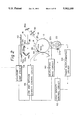
- FIG. 2 schematically illustrates one example of an image density control system in the embodiment of FIG. 1;
- FIG. 4 is a four-quadrant chart representing fluctuations of copied image density versus developing capability and fluctuations of the sensitivity of a photo-sensitive material
- FIG. 5 schematically illustrates one example of an image density control system in another embodiment of the present invention.
- FIG. 6 is a flowchart showing part of a micro-computer control program used in the embodiment cf FIG. 5;
- FIG. 7 is a timechart showing timing for obtaining density pattern signals
- FIG. 8, 9 and 10 are flowcharts showing parts of microcomputer control programs used in the embodiment of FIG. 5;
- FIGS. 11 schematically illustrates an example of an image density control system in a further embodiment of the present invention.
- FIG. 12 shows the relationship between toner density and output voltage of a permeability sensor
- FIG. 13 is a flowchart showing part of a microcomputer control program used in a still further embodiment of the present invention.
- FIG. 1 illustrates the mechanical structure of a color copying machine as an embodiment of the present invention. Disposed in order at substantially the center of the copying machine are a photosensitive drum 10 which can carry a latent image thereon and a transfer drum 12 which transfers a toner image derived by development of a latent image on the photo-sensitive drum 10.
- an electrostatic charger 14 which initially charges uniformly the surface of the photosensitive drum 10
- an exposing optical system 16 which exposes the uniformly charged surface of the photosensitive drum 10 to an optical image of an original document to form an electrostatic latent image
- an eraser 18 which irradiates light onto the photosensitive drum 10 except for the image area and for a density detection pattern to be described later in more detail so as to eliminate the remaining electric charges from the drum 10.
- the drum 10 Furthermore, disposed around the drum 10 are black (BK), yellow (Y), magenta (M) and cyan (C) toner developing devices 20, 22, 24 and 26 which supply respective toners to the latent images for developing the images to form respective color toner images, the aforementioned transfer drum 12 which can hold a recording sheet paper for transferring different color toner images sequentially onto the recording sheet, a cleaner device 28 which cleans the remaining toners on the drum surface after transfer, and a discharger 30 which eliminates the remaining charges on the drum 10 after transfer.
- the transfer drum 12 has a separating charger 32 and a pickoff finger 34 which cooperate to separate the transferred recording paper from the transfer drum 12.
- a fusing device 38 is disposed at an end of a carrier belt 36 which carries the recording paper separated from the transfer drum 12 in order to fuse, press and fix the toner image to the recording paper.
- a discharged paper tray 40 is provided at the exit of the fusing device 38.
- the exposing optical system 16 further includes a contact glass plate 42 disposed on the top of the copying machine for receiving an original document thereon, an exposure lamp 44 which irradiates scanning light onto the original document on the contact glass 42, reflective mirrors 46a, 46b, 46c and 46d and a focusing lens 48 which focuses the reflected light from the original document via the reflective mirrors onto the photosensitive drum 10, and a color separation filter 50 which separates the optical image into color images.
- a density sensing pattern 52 described in detail later is provided near one end of the contact glass plate 42.
- a photoelectric sensor 54 is provided behind the transfer drum 12 around the photosensitive drum 10 in order to sense a deposited quantity of toner on a toner image of the density sensing pattern, formed on the photosensitive drum 10.
- Permeability sensors 20a, 22a, 24a and 26a are disposed in the developing devices 20, 22, 24 and 26, respectively, in order to sense the toner densities on the basis of changes in the permeabilities of the respective developers.
- FIG. 2 schematically illustrates one example of an image density control system in the embodiment of FIG. 1.
- the image density control to be described below are performed actually for each of colors, namely, black, yellow, magenta and cyan.
- a medium density pattern 52a having a density of from 0.3 to 0.4 and a low density pattern 52b of white background are provided as the density patterns 52 outside the image area (contact glass plate 42).
- These density patterns are exposed by means of the optical system 16 onto the photosensitive drum 10 to thereby form corresponding latent images thereon.
- the respective formed latent images are developed by the yellow toner into toner images each having a respective one of a medium and a low density patterns.
- the respective deposited quantities of yellow toner are sensed by the photoelectric sensor 54.
- the sensor 54 includes a light emitting element 54a made, for example, of a light emitting diode and a photodetector 54b made, for example, of a photodiode so that the light emitted from the element 54a is reflected by the toner image and detected by the photodetector 54b thereby to detect the respective deposited quantities of the toner.
- a detection signal derived based on each of the density patterns from the photoelectric sensor 54 is applied to a low and medium density control circuit 56 which has two functions. One is to provide a control value of a voltage applied to the exposure lamp 44 in order to control the medium density of the image, and the other is to provide a control value of the developing bias voltage in order to control the density of the low density portion of the image.
- control circuit 56 includes means for storing the values of detection signals on the deposited toner quantities on the low and medium density pattern images, means for calculating the ratio of the stored values, means for comparing a reference value and the value of the ratio obtained by the calculation, and means for determining control value of the voltage applied to the exposure lamp 44 in accordance with the result provided by the comparing means.
- the signal representative of the determined control value is sent to an exposure lamp driver 58 to control the voltage applied to the exposure lamp 44 in accordance with that signal.
- the control circuit 56 for providing the latter function includes means for comparing a reference value and the stored value on the detection signal indicative of the quantity of toner deposited on the low density pattern image, and means for determining a control value of the developing bias voltage in accordance with the value provided by the comparing means.
- the signal representative of the determined control value is sent to a developing bias circuit 60 to control the bias voltage applied to a developing roller 22b in the developing device 22 in accordance with that signal.
- the permeability sensor 22a is a well-known type wherein a developer including toner with magnetic carriers is guided through a coil of a resonant circuit, and that the toner density is sensed by sensing a change in the inductance according to the relative quantity of magnetic carriers relative to the toner in the developer.
- the detection signal from the permeability sensor 22a is applied to a high density control circuit 62 which has a function of determining whether the toner should be supplemented to correct the high density portion of the image.
- the control circuit 62 includes means for comparing a signal from the permeability sensor 22a with a reference to determine whether the toner density is below the reference value.
- the output from the comparing means is supplied to a toner supplementing driver 64 to control the drive of a toner supplementing mechanism (not shown) in the developing device 22.
- a process for forming a color image in the embodiment includes the repetition of the steps of (a) electrical charging of the photosensitive drum 10, (b) color separation and exposure on the .photosensitive drum 10, (c) development by toners and (d) transfer onto recording paper on the transfer drum 12, for each black, yellow, magenta and cyan color toner. Then, the superposed toner images of four colors are at one time fused and fixed at the fusing device 38 to form a color image finally.
- the medium and low density patterns 52a and 52b are exposed outside the image area on the photosensitive drum 10 thereby to form latent images having the corresponding potentials thereon.
- These latent images are developed by the color toners during each repetition of the steps for forming a color image, above described, into corresponding density i.e., medium and low, toner images.
- the quantities of toners deposited on those toner images are sensed by the photoelectric sensor 54.
- the voltage applied to the exposure lamp 44 and hence the quantity of exposure are controlled in accordance with the sensed quantities of the toner so that the density of the medium density portion of the image is controlled to a proper value. This control is performed for each repetition cycle, namely, for each toner color.
- the density of the low density, namely background density, of the image is controlled by controlling the developing bias, as mentioned above, in accordance with the quantity of a toner deposited on the image of the low density pattern as sensed by the photoelectric sensor 54. This control is performed for each color.
- the developing bias voltage is corrected in accordance with fluctuations of the potential of the background, and hence of the deposited low density toner quantity caused by the aging of the photosensitive drum 10 due to its fatigue. Thus the density of the low density portions of the image is properly corrected and smears in the background of the image are eliminated.
- the respective toner densities are controlled in accordance with the outputs from the permeability sensors 20a, 22a, 24a and 26a of the corresponding developing devices 20, 22, 24 and 26, as mentioned above.
- the respective color toner densities in the developing devices are corrected and controlled to corresponding predetermined values even if they may fluctuate, and the density of the high density portions of the image is properly adjusted.
- the high density portions of the image are different from the medium and low density portions of the image in that no large color fluctuations occur due to second and third colors even if a particular color may slightly be thinned. Thus a satisfactory color balance is maintained even by toner density control having a relatively low control responsiveness, as mentioned above.
- FIG. 3 shows the original document density versus copied image density characteristic for each toner color (C, M or Y) obtained when color balance is maintained.
- C, M or Y toner color
- the original document density copied image density characteristic will change in accordance with fluctuation of developing capability (second quadrant) such as toner density and a quantity of electric toner charges, and potential fluctuation in a photosensitive material (fourth quadrant). Therefore, as in the embodiment, a satisfactory color balance can not be maintained until the respective densities of the low, medium and high density portions of the image for each color are controlled. In this case, density fluctuations of the medium density portions of the image are likely to be noticeable, so that as in the embodiment, rapid correction and control are required for each color.
- FIG. 5 schematically illustrates one example of an image density control system of another embodiment of the present invention. This embodiment is the same in structure as the embodiment of FIGS. 1 and 2 except for the image density control system.
- the image density control system includes a microcomputer which basically comprises a central processing unit (CPU) 66, a read only memory (ROM) 68, a random access memory (RAM) 70, an input/output (I/O) interface 72 and a bus 74 connecting these elements.
- the microcomputer has the same functions as the low and medium density control circuit 56 and the high density control circuit 62 of FIG. 2.
- the analog detection signals from the photoelectric sensor 54 and permeability sensor 22a are converted by analog-to-digital (A/D) converters 76 and 78, respectively, to the corresponding digital signals for use in the microcomputer.
- the resulting digital signals are applied to the I/O interface 72.
- the output detection signals from other permeability sensors 20a, 24a and 26a are input to the I/O interface 72 through other A/D converters (not shown).
- Exposure lamp driver 158, developing bias circuit 160 and toner supplementing driver 164 are the same in function as the exposure lamp driver 58, developing bias circuit 60 and toner supplementing driver 64, respectively, in FIG. 2 except that they are driven by the digital signals from the I/O interface 74.
- FIGS. 6, 8, 9 and 10 schematically illustrate control programs for the microcomputer of FIG. 5. The operation of this embodiment will now be described using these flowcharts.
- the microcomputer judges whether or not a predetermined time period t a is elapsed after a timer provided in the CPU66 starts the counting operation. In other words, whether or not the position of the toner image of the medium density pattern 52a is opposed to the photoelectric sensor 54, is judged. If "YES", namely if t a was elapsed, the program proceeds to a step S 2 .
- the microcomputer receives the digital signal from the A/D converter 76 and stores the received signal in the RAM70 as D m .
- the photoelectric sensor 54 outputs the detection signal corresponding to the medium density pattern portion when the time period t a is elapsed after the starting time of count operation by the timer which may be at the starting time of exposure operation.
- step S 3 the microcomputer judges whether or not a predetermined time period t b is elapsed after the starting time, namely whether the position of the toner image of the low density pattern 52b is opposed to the photoelectric sensor 54. Only when "YES”, the program proceeds to a step S 4 wherein the digital signal from the A/D converter 76 is input and then stored in the RAM 70 as D e .
- the stored values D m and D e represent the detected values of the deposited toner quantities on the medium and low density pattern images, respectively.
- the microcomputer calculates ratio of D m /D e and then stores the calculated ratio in the RAM 70 as data P.
- the microcomputer compares the stored value P with a reference value P r which
- the microcomputer compares the stored value D e with a reference value D r which is preliminarily stored in the ROM 68 by calculating D e -D r , and then stores the calculated value D e -D r in the RAM 70 as D d .
- a program shown in FIG. 8 is executed before each exposure operation.
- the stored value P d is read out from the RAM 70.
- a step S 12 whether or not the value P d is greater than zero is judged. If "YES”, the program proceeds to a step S 13 wherein a signal is output from the microcomputer to the exposure lamp driver 158 such that the voltage applied to the exposure lamp 44 is increased in accordance with the value P d . If "NO” in the step S 12 , the program proceeds to a step S 14 wherein whether or not the value P d is smaller than zero is judged.
- step S 14 the program proceeds to a step S 15 wherein a signal is applied to the exposure lamp driver 158 so that the voltage applied to the exposure lamp 44 is decreased in accordance with the value P d . If "NO” in the step S 14 , the program proceeds to a step S 16 wherein a reference voltage is applied to the exposure lamp 44.
- a program shown in FIG. 9 is executed before application of the developing bias voltage.
- a step S 2 of the program, the stored value D d is read out from the RAM 70. Then, in a step S 22 , whether or not the value D d is greater than zero is judged. If “YES”, the program proceeds to a step S 23 wherein a signal is output from the microcomputer to the developing bias circuit 160 so that the developing bias voltage is increased in accordance with the value D d . If "NO” in the step S 22 , the program proceeds to a step S 24 wherein whether or not the value D d is smaller than zero is judged. If "YES” in the step S 24 , the program proceeds to a step S 25 wherein a signal is applied to the bias circuit 160 so as to decrease the developing bias voltage in accordance with the value D d .
- the density of the high density portions of the image is controlled by the program shown in FIG. 10.
- a step S 31 of the program the digital signal from the A/D converter 78 is input to the microcomputer and stored in the RAM 70 as D h .
- a step S 32 whether or not the stored value D h is smaller than a reference value D t which is preliminarily stored in the ROM 68 is judged. If "YES”, the program proceeds to a step S 33 wherein a signal is output from the microcomputer to the toner supplementing driver 164 so as to supply more toner causing the toner density to increase. If "NO", no toner is supplemented.
- FIG. 11 schematically illustrates an example of an image density control system of a further embodiment of the present invention.
- the particular embodiment is the same in structure as the embodiment of FIGS. 1 and 2 except for the image density control system.
- the output detection signal from the permeability sensor 22a and the output detection signal from the photoelectric sensor 54 are used to control the density of the high density portion of the image.
- the high density control circuit 162 includes a comparator which compares the output detection signal from the permeability sensor 22a with a reference value to determine whether the toner density is below a reference, and means which corrects the reference value in accordance with fluctuations of electric toner charges.
- a fluctuation of toner charges corresponds to variation of the ratio of the value of a detection signal indicative of the deposited quantity of toner on the low density pattern image to the value of a detection indicative of the deposited quantity of toner on the medium density pattern image, the ratio being calculated by the low and medium density control circuit 56.
- the reference value for the toner density for the output voltage of detection signal (axis of ordinates) from the permeability sensor 22a is lowered and the toner density (axis of abscissas) is raised when the image density is low and the quantity of toner charges is large, as shown in FIG. 12.
- the reference value for the toner density for the output voltage from the permeability sensor 22a is raised and the toner density (axis of abscissas) is lowered.
- a range in which the reference value for the toner density can be corrected should have a predetermined zone in order to avoid the formation of an abnormal image due to operational malfunction of the photoelectric sensor.
- the characteristics of the toner and developer, especially the quantity of toner charges, will fluctuate by ⁇ 20 to 30% depending on their environments of use and their aging. By such fluctuations of the characteristic of the developer, the image density will become high or low wholly even if the color balance is maintained.
- the toner densities in the developing devices 20, 22, 24 and 26 for the respective colors are controlled such that the quantities of electric toner charges are maintained constant at all time. As a result, the density of the high density image portion is adjusted to an appropriate value and the overall density balance of the image is maintained satisfactory.
- FIG. 13 is a flowchart illustrating a control program for the microcomputer used in a further embodiment of the present invention. Since this embodiment is the same in mechanical structure as that of FIG. 5, its description will be omitted. Furthermore, the advantage of this embodiment is the same as that of the embodiment of FIG. 11.
- the program used in the FIG. 13 embodiment differs from the program shown in FIG. 10 in the following points.
- the program of FIG. 13 proceeds after the step S 31 to an additional step S 34 wherein a reference value D t' is corrected in accordance with the value P d calculated by the program of FIG. 6 and stored in the RAM 70. The correction is carried out so that the reference value D t' is increased when the value P d is large and vice versa.
- the next step S 35 whether or not the stored value D h is smaller than the corrected reference value D t' is judged. Otherwise, operation of this program is the same as that of the program of FIG. 10.
- the medium and low density patterns 52a and 52b are prepared in advance and exposed to light thereby to form latent images of medium and low densities on the photosensitive drum 10.
- latent images may be formed by directly controlling the potential of electric charges on a particular portion of the photosensitive drum 10.
- the latent image of low density can be easily obtained by lowering the potential of the appropriate portion of the drum surface by the eraser 18 to the remaining potential.
- the voltage applied to the exposure lamp 44 and the developing bias voltage are controlled to control the densities of the medium and low density portions of the image
- the voltage applied to the charger 14 may be controlled instead.
Landscapes
- Physics & Mathematics (AREA)
- General Physics & Mathematics (AREA)
- Engineering & Computer Science (AREA)
- Microelectronics & Electronic Packaging (AREA)
- Control Or Security For Electrophotography (AREA)
- Color Electrophotography (AREA)
Applications Claiming Priority (4)
| Application Number | Priority Date | Filing Date | Title |
|---|---|---|---|
| JP62329023A JP2807229B2 (ja) | 1987-12-25 | 1987-12-25 | カラー画像形成装置の作像条件制御方法 |
| JP62329024A JP2719138B2 (ja) | 1987-12-25 | 1987-12-25 | カラー画像形成装置の作像条件制御方法 |
| JP62-329023 | 1987-12-25 | ||
| JP62-329024 | 1987-12-25 |
Related Parent Applications (1)
| Application Number | Title | Priority Date | Filing Date |
|---|---|---|---|
| US07289253 Continuation | 1988-12-23 |
Publications (1)
| Publication Number | Publication Date |
|---|---|
| US5083160A true US5083160A (en) | 1992-01-21 |
Family
ID=26573059
Family Applications (1)
| Application Number | Title | Priority Date | Filing Date |
|---|---|---|---|
| US07/626,334 Expired - Fee Related US5083160A (en) | 1987-12-25 | 1990-12-13 | Image density control method and color image forming apparatus |
Country Status (3)
| Country | Link |
|---|---|
| US (1) | US5083160A (de) |
| DE (1) | DE3843672C2 (de) |
| GB (1) | GB2212419B (de) |
Cited By (29)
| Publication number | Priority date | Publication date | Assignee | Title |
|---|---|---|---|---|
| US5196886A (en) * | 1991-06-26 | 1993-03-23 | Kabushiki Kaisha Toshiba | Electrophotographic image forming apparatus including means for correcting density drift |
| US5200783A (en) * | 1990-08-30 | 1993-04-06 | Sharp Kabushiki Kaisha | Black image density correcting device |
| US5253031A (en) * | 1990-05-31 | 1993-10-12 | Minolta Camera Kabushiki Kaisha | Method of forming a reference pattern for adjusting image density in copying machines |
| US5321468A (en) * | 1992-09-24 | 1994-06-14 | Kabushiki Kaisha Toshiba | Image forming apparatus having inference means and method of manufacturing the same |
| US5351107A (en) * | 1992-09-24 | 1994-09-27 | Kabushiki Kaisha Toshiba | Image forming apparatus and method having image density correcting function |
| US5365313A (en) * | 1992-09-24 | 1994-11-15 | Kabushiki Kaisha Toshiba | Image forming apparatus for controlling image density using logarithm compressing means |
| US5398099A (en) * | 1992-09-24 | 1995-03-14 | Kabushiki Kaisha Toshiba | Image forming apparatus with bias means for preventing toner particles from clouding optical components |
| US5483328A (en) * | 1991-11-11 | 1996-01-09 | Fujitsu, Ltd. | Toner supply control system and method |
| US5502550A (en) * | 1991-08-27 | 1996-03-26 | Canon Kabushiki Kaisha | Image forming apparatus and method |
| US5570165A (en) * | 1994-02-25 | 1996-10-29 | Ricoh Company, Ltd. | Method of controlling toner density detection |
| US5581221A (en) * | 1993-12-22 | 1996-12-03 | Minolta Co. Ltd. | Electrophotographic image forming apparatus |
| US5864353A (en) * | 1995-02-03 | 1999-01-26 | Indigo N.V. | C/A method of calibrating a color for monochrome electrostatic imaging apparatus |
| US5983060A (en) * | 1997-03-31 | 1999-11-09 | Ricoh Company, Ltd. | Image forming apparatus which removes a surface potential of an intermediate transfer member |
| US20010028812A1 (en) * | 2000-03-30 | 2001-10-11 | Ricoh Company, Ltd. | Belt apparatus used in image formation, and an image formation apparatus |
| US6324356B1 (en) * | 1999-11-05 | 2001-11-27 | Ricoh Company, Ltd | Toner save method and system for image duplicating devices |
| US6505010B1 (en) * | 1991-08-26 | 2003-01-07 | Canon Kabushiki Kaisha | Image forming apparatus |
| US6505024B2 (en) | 1998-11-24 | 2003-01-07 | Ricoh Company, Ltd. | Method and apparatus for image forming performing improved cleaning and discharging operations on image forming associated members |
| US20030118226A1 (en) * | 2001-11-23 | 2003-06-26 | Robin Winsor | Balancing areas of varying density in a digital image |
| USRE38206E1 (en) | 1992-08-28 | 2003-07-29 | Ricoh Company, Ltd. | Image transferring device for an image forming apparatus |
| US6611672B2 (en) | 2000-09-26 | 2003-08-26 | Ricoh Company, Ltd. | Image forming apparatus, monocolor image forming apparatus, toner recycling apparatus and intermediate transfer member |
| US20040005177A1 (en) * | 2002-05-17 | 2004-01-08 | Hajime Oyama | Fixing device and image forming apparatus using the same |
| US20040141765A1 (en) * | 2002-02-20 | 2004-07-22 | Hidetsugu Shimura | Image formation apparatus and image formation method |
| US20040190946A1 (en) * | 2002-12-27 | 2004-09-30 | Shigekazu Enoki | Magnetic carrier, two-component developer, development method, development device and image forming apparatus of electrophotography |
| US20040208661A1 (en) * | 2002-08-30 | 2004-10-21 | Takashi Kitagawa | Image formation controlling method and image forming apparatus |
| US20040265015A1 (en) * | 2003-06-26 | 2004-12-30 | Takayuki Koike | Developing device, image forming apparatus, process cartridge, and developing method |
| US20040265014A1 (en) * | 2003-06-27 | 2004-12-30 | Nobutaka Takeuchi | Developing unit and image forming apparatus |
| US20050002680A1 (en) * | 2003-03-31 | 2005-01-06 | Brother Kogyo Kabushiki Kaisha | Image forming device that performs density detection |
| US20050002701A1 (en) * | 2003-04-16 | 2005-01-06 | Hiroshi Ikeguchi | Developing device, image forming apparatus, and process cartridge |
| US20050025535A1 (en) * | 2003-06-30 | 2005-02-03 | Yasushi Koichi | Image forming apparatus and image forming method |
Families Citing this family (8)
| Publication number | Priority date | Publication date | Assignee | Title |
|---|---|---|---|---|
| JPH02149864A (ja) * | 1988-12-01 | 1990-06-08 | Ricoh Co Ltd | 画像形成装置 |
| GB2244350B (en) * | 1990-04-27 | 1994-08-10 | Ricoh Kk | Image forming method and apparatus for the same |
| US5293198A (en) * | 1990-08-10 | 1994-03-08 | Ricoh Company, Ltd. | Image forming apparatus for controlling the dynamic range of an image |
| DE69205456T2 (de) * | 1991-02-22 | 1996-03-28 | Canon Kk | Bilderzeugendes Gerät. |
| DE69212915T2 (de) * | 1991-06-18 | 1997-01-02 | Canon Kk | Bilderzeugungsgerät mit der Einstellvorrichtung für die Bilderzeugungsbedingungen ansprechend auf ein Testmusterbild |
| JPH05333650A (ja) * | 1992-05-27 | 1993-12-17 | Konica Corp | トナー付着量検出方法及び画像形成方法 |
| US5652952A (en) * | 1994-09-20 | 1997-07-29 | Mita Industrial Co., Ltd. | Method of adjusting density detecting device used for image forming apparatus |
| US6081677A (en) * | 1996-08-02 | 2000-06-27 | Oce Printing Systems Gmbh | Process for optimizing a half-tone reproduction on a photoconductor of electrophotographic printers and copiers |
Citations (12)
| Publication number | Priority date | Publication date | Assignee | Title |
|---|---|---|---|---|
| US2956487A (en) * | 1955-03-23 | 1960-10-18 | Rca Corp | Electrostatic printing |
| GB1559341A (en) * | 1976-12-31 | 1980-01-16 | Xerox Corp | Method of controlling an electrostatographic copying machine |
| US4277162A (en) * | 1978-07-13 | 1981-07-07 | Ricoh Company, Ltd. | Electrophotographic apparatus comprising density sensor means |
| US4318610A (en) * | 1980-04-21 | 1982-03-09 | Xerox Corporation | Control system for an electrophotographic printing machine |
| US4348099A (en) * | 1980-04-07 | 1982-09-07 | Xerox Corporation | Closed loop control of reproduction machine |
| US4377338A (en) * | 1981-08-07 | 1983-03-22 | International Business Machines Corporation | Method and apparatus for copier quality monitoring and control |
| DE3242384A1 (de) * | 1981-11-17 | 1983-05-26 | Ricoh Co., Ltd., Tokyo | Verfahren zum steuern eines bildschwaerzungsgrades in einem elektrophotographischen verfahren |
| US4468112A (en) * | 1981-02-18 | 1984-08-28 | Canon Kabushiki Kaisha | Developer concentration controlling device |
| JPS6057869A (ja) * | 1983-09-10 | 1985-04-03 | Ricoh Co Ltd | カラ−電子写真用トナ−濃度測定装置 |
| JPS6080865A (ja) * | 1983-10-11 | 1985-05-08 | Fuji Xerox Co Ltd | カラ−複写機 |
| US4519695A (en) * | 1982-02-12 | 1985-05-28 | Ricoh Company, Ltd. | Image density control method for electrophotography |
| JPS6392967A (ja) * | 1986-10-07 | 1988-04-23 | Konica Corp | 多色像形成装置 |
Family Cites Families (1)
| Publication number | Priority date | Publication date | Assignee | Title |
|---|---|---|---|---|
| JPH0680865A (ja) * | 1990-08-06 | 1994-03-22 | Toyobo Co Ltd | ポリエステル樹脂組成物 |
-
1988
- 1988-12-20 GB GB8829653A patent/GB2212419B/en not_active Expired
- 1988-12-23 DE DE3843672A patent/DE3843672C2/de not_active Expired - Fee Related
-
1990
- 1990-12-13 US US07/626,334 patent/US5083160A/en not_active Expired - Fee Related
Patent Citations (13)
| Publication number | Priority date | Publication date | Assignee | Title |
|---|---|---|---|---|
| US2956487A (en) * | 1955-03-23 | 1960-10-18 | Rca Corp | Electrostatic printing |
| GB1559341A (en) * | 1976-12-31 | 1980-01-16 | Xerox Corp | Method of controlling an electrostatographic copying machine |
| US4277162A (en) * | 1978-07-13 | 1981-07-07 | Ricoh Company, Ltd. | Electrophotographic apparatus comprising density sensor means |
| US4348099A (en) * | 1980-04-07 | 1982-09-07 | Xerox Corporation | Closed loop control of reproduction machine |
| US4318610A (en) * | 1980-04-21 | 1982-03-09 | Xerox Corporation | Control system for an electrophotographic printing machine |
| US4468112A (en) * | 1981-02-18 | 1984-08-28 | Canon Kabushiki Kaisha | Developer concentration controlling device |
| US4377338A (en) * | 1981-08-07 | 1983-03-22 | International Business Machines Corporation | Method and apparatus for copier quality monitoring and control |
| DE3242384A1 (de) * | 1981-11-17 | 1983-05-26 | Ricoh Co., Ltd., Tokyo | Verfahren zum steuern eines bildschwaerzungsgrades in einem elektrophotographischen verfahren |
| US4572654A (en) * | 1981-11-17 | 1986-02-25 | Ricoh Company, Ltd. | Image density control method for electrophotography |
| US4519695A (en) * | 1982-02-12 | 1985-05-28 | Ricoh Company, Ltd. | Image density control method for electrophotography |
| JPS6057869A (ja) * | 1983-09-10 | 1985-04-03 | Ricoh Co Ltd | カラ−電子写真用トナ−濃度測定装置 |
| JPS6080865A (ja) * | 1983-10-11 | 1985-05-08 | Fuji Xerox Co Ltd | カラ−複写機 |
| JPS6392967A (ja) * | 1986-10-07 | 1988-04-23 | Konica Corp | 多色像形成装置 |
Cited By (49)
| Publication number | Priority date | Publication date | Assignee | Title |
|---|---|---|---|---|
| US5253031A (en) * | 1990-05-31 | 1993-10-12 | Minolta Camera Kabushiki Kaisha | Method of forming a reference pattern for adjusting image density in copying machines |
| US5200783A (en) * | 1990-08-30 | 1993-04-06 | Sharp Kabushiki Kaisha | Black image density correcting device |
| US5196886A (en) * | 1991-06-26 | 1993-03-23 | Kabushiki Kaisha Toshiba | Electrophotographic image forming apparatus including means for correcting density drift |
| US6505010B1 (en) * | 1991-08-26 | 2003-01-07 | Canon Kabushiki Kaisha | Image forming apparatus |
| US5502550A (en) * | 1991-08-27 | 1996-03-26 | Canon Kabushiki Kaisha | Image forming apparatus and method |
| US5655185A (en) * | 1991-08-27 | 1997-08-05 | Canon Kabushiki Kaisha | Image forming apparatus and method |
| US5483328A (en) * | 1991-11-11 | 1996-01-09 | Fujitsu, Ltd. | Toner supply control system and method |
| USRE38206E1 (en) | 1992-08-28 | 2003-07-29 | Ricoh Company, Ltd. | Image transferring device for an image forming apparatus |
| US5321468A (en) * | 1992-09-24 | 1994-06-14 | Kabushiki Kaisha Toshiba | Image forming apparatus having inference means and method of manufacturing the same |
| US5351107A (en) * | 1992-09-24 | 1994-09-27 | Kabushiki Kaisha Toshiba | Image forming apparatus and method having image density correcting function |
| US5365313A (en) * | 1992-09-24 | 1994-11-15 | Kabushiki Kaisha Toshiba | Image forming apparatus for controlling image density using logarithm compressing means |
| US5398099A (en) * | 1992-09-24 | 1995-03-14 | Kabushiki Kaisha Toshiba | Image forming apparatus with bias means for preventing toner particles from clouding optical components |
| US5581221A (en) * | 1993-12-22 | 1996-12-03 | Minolta Co. Ltd. | Electrophotographic image forming apparatus |
| US5570165A (en) * | 1994-02-25 | 1996-10-29 | Ricoh Company, Ltd. | Method of controlling toner density detection |
| US5864353A (en) * | 1995-02-03 | 1999-01-26 | Indigo N.V. | C/A method of calibrating a color for monochrome electrostatic imaging apparatus |
| US5983060A (en) * | 1997-03-31 | 1999-11-09 | Ricoh Company, Ltd. | Image forming apparatus which removes a surface potential of an intermediate transfer member |
| US6505024B2 (en) | 1998-11-24 | 2003-01-07 | Ricoh Company, Ltd. | Method and apparatus for image forming performing improved cleaning and discharging operations on image forming associated members |
| US6324356B1 (en) * | 1999-11-05 | 2001-11-27 | Ricoh Company, Ltd | Toner save method and system for image duplicating devices |
| US20010028812A1 (en) * | 2000-03-30 | 2001-10-11 | Ricoh Company, Ltd. | Belt apparatus used in image formation, and an image formation apparatus |
| US7149446B2 (en) | 2000-03-30 | 2006-12-12 | Ricoh Company, Ltd. | Belt apparatus used in image formation, and an image formation apparatus |
| US6839531B2 (en) | 2000-03-30 | 2005-01-04 | Ricoh Company, Ltd. | Belt apparatus used in image formation, and an image formation apparatus |
| US20050226643A1 (en) * | 2000-03-30 | 2005-10-13 | Masanori Saitoh | Belt apparatus used in image formation, and an image formation apparatus |
| US6611672B2 (en) | 2000-09-26 | 2003-08-26 | Ricoh Company, Ltd. | Image forming apparatus, monocolor image forming apparatus, toner recycling apparatus and intermediate transfer member |
| US7092581B2 (en) * | 2001-11-23 | 2006-08-15 | Imaging Dynamics Company Ltd. | Balancing areas of varying density in a digital image |
| US20070009145A1 (en) * | 2001-11-23 | 2007-01-11 | Robin Winsor | Balancing areas of varying density in a digital image |
| US20030118226A1 (en) * | 2001-11-23 | 2003-06-26 | Robin Winsor | Balancing areas of varying density in a digital image |
| US7072597B2 (en) | 2002-02-20 | 2006-07-04 | Seiko Epson Corporation | Image forming apparatus and image method for forming toner images with optimized patch image density |
| EP1477866A4 (de) * | 2002-02-20 | 2009-12-09 | Seiko Epson Corp | Bilderzeugungsvorrichtung und bilderzeugungsverfahren |
| US7260336B2 (en) | 2002-02-20 | 2007-08-21 | Seiko Epson Corporation | Image forming apparatus and image forming method for performing density control of toner images |
| US20060204261A1 (en) * | 2002-02-20 | 2006-09-14 | Seiko Epson Corporation | Image forming apparatus and image forming method |
| US20040141765A1 (en) * | 2002-02-20 | 2004-07-22 | Hidetsugu Shimura | Image formation apparatus and image formation method |
| US7664446B2 (en) | 2002-05-17 | 2010-02-16 | Ricoh Company, Ltd. | Image forming apparatus and a fixing device having a rigid heat-insulating layer |
| US20040005177A1 (en) * | 2002-05-17 | 2004-01-08 | Hajime Oyama | Fixing device and image forming apparatus using the same |
| US6847791B2 (en) * | 2002-08-30 | 2005-01-25 | Sharp Kabushiki Kaisha | Image formation controlling method and image forming apparatus |
| US20040208661A1 (en) * | 2002-08-30 | 2004-10-21 | Takashi Kitagawa | Image formation controlling method and image forming apparatus |
| US7020421B2 (en) | 2002-12-27 | 2006-03-28 | Ricoh Company, Ltd. | Magnetic carrier, two-component developer, development method, development device and image forming apparatus of electrophotography |
| US20040190946A1 (en) * | 2002-12-27 | 2004-09-30 | Shigekazu Enoki | Magnetic carrier, two-component developer, development method, development device and image forming apparatus of electrophotography |
| US20050002680A1 (en) * | 2003-03-31 | 2005-01-06 | Brother Kogyo Kabushiki Kaisha | Image forming device that performs density detection |
| US7099600B2 (en) * | 2003-03-31 | 2006-08-29 | Brother Kogyo Kabushiki Kaisha | Image forming device that performs density detection |
| US20060285864A1 (en) * | 2003-03-31 | 2006-12-21 | Brother Kogyo Kabushiki Kaisha | Image forming device that performs density detection |
| US7400840B2 (en) | 2003-03-31 | 2008-07-15 | Brother Kogyo Kabushiki Kaisha | Image forming device that performs density detection |
| US20050002701A1 (en) * | 2003-04-16 | 2005-01-06 | Hiroshi Ikeguchi | Developing device, image forming apparatus, and process cartridge |
| US7035575B2 (en) | 2003-04-16 | 2006-04-25 | Ricoh Company, Ltd. | Developing device, image forming apparatus, and process cartridge |
| US7245861B2 (en) | 2003-06-26 | 2007-07-17 | Ricoh Company, Limited | Developing device, image forming apparatus and process cartridge including the developing device, and developing method |
| US20040265015A1 (en) * | 2003-06-26 | 2004-12-30 | Takayuki Koike | Developing device, image forming apparatus, process cartridge, and developing method |
| US7116932B2 (en) | 2003-06-27 | 2006-10-03 | Ricoh Company, Limited | Developing unit and image forming apparatus |
| US20040265014A1 (en) * | 2003-06-27 | 2004-12-30 | Nobutaka Takeuchi | Developing unit and image forming apparatus |
| US7162187B2 (en) | 2003-06-30 | 2007-01-09 | Ricoh Company, Ltd. | Image forming apparatus and image forming method |
| US20050025535A1 (en) * | 2003-06-30 | 2005-02-03 | Yasushi Koichi | Image forming apparatus and image forming method |
Also Published As
| Publication number | Publication date |
|---|---|
| GB8829653D0 (en) | 1989-02-15 |
| DE3843672A1 (de) | 1989-07-13 |
| GB2212419B (en) | 1991-12-04 |
| GB2212419A (en) | 1989-07-26 |
| DE3843672C2 (de) | 1994-02-03 |
Similar Documents
| Publication | Publication Date | Title |
|---|---|---|
| US5083160A (en) | Image density control method and color image forming apparatus | |
| US5754918A (en) | Electrostatic control with compensation for coupling effects | |
| US5293198A (en) | Image forming apparatus for controlling the dynamic range of an image | |
| US5950040A (en) | Feedback control system for controlling developability of a xerographic imaging device | |
| US4989043A (en) | Color-balance control method | |
| EP0797124B1 (de) | Gerät und Verfahren zur Überwachung und Steuerung von elektrischen Parametern einer Bilderzeugungsfläche | |
| US5835235A (en) | Image forming apparatus which establishes image formation values using environmentally sensitive references | |
| EP0517905B1 (de) | Kontrolle des elektrostatografischen Farbprozesses mittels Tonerentwicklungscharakteristik | |
| US5200783A (en) | Black image density correcting device | |
| JPH05333652A (ja) | 画像形成装置 | |
| JP3264695B2 (ja) | 画像形成装置 | |
| US5485191A (en) | Image forming apparatus having tone correcting function | |
| JPS6057868A (ja) | 画像濃度制御方法 | |
| JPS61254961A (ja) | カラ−画像形成装置 | |
| JP2807229B2 (ja) | カラー画像形成装置の作像条件制御方法 | |
| JP2719138B2 (ja) | カラー画像形成装置の作像条件制御方法 | |
| JP3711830B2 (ja) | 画像形成装置 | |
| US5389955A (en) | Image forming apparatus directly correcting an image data in response to changes in image potential data | |
| JPH08123110A (ja) | 画像形成装置およびその画像濃度制御方法 | |
| JPH0135347B2 (de) | ||
| US5794098A (en) | Leading edge electrostatic voltmeter readings in the image-on-image electrophotographic printing process | |
| JP2698095B2 (ja) | 多色画像形成装置のカラーバランス制御方法 | |
| JP2698094B2 (ja) | 多色画像形成装置のカラーバランス制御方法 | |
| JP2746394B2 (ja) | 画像形成装置の作像条件制御方法 | |
| JPH05100578A (ja) | 画像形成装置 |
Legal Events
| Date | Code | Title | Description |
|---|---|---|---|
| AS | Assignment |
Owner name: RICOH COMPANY, LTD., A JOINT-STOCK COMPANY OF JAPA Free format text: ASSIGNMENT OF ASSIGNORS INTEREST.;ASSIGNORS:SUZUKI, KOHJI;MASUMURA, MASAO;OYAMA, HAJIME;AND OTHERS;REEL/FRAME:005803/0788 Effective date: 19890126 |
|
| FPAY | Fee payment |
Year of fee payment: 4 |
|
| FPAY | Fee payment |
Year of fee payment: 8 |
|
| REMI | Maintenance fee reminder mailed | ||
| LAPS | Lapse for failure to pay maintenance fees | ||
| STCH | Information on status: patent discontinuation |
Free format text: PATENT EXPIRED DUE TO NONPAYMENT OF MAINTENANCE FEES UNDER 37 CFR 1.362 |
|
| FP | Lapsed due to failure to pay maintenance fee |
Effective date: 20040121 |