US508301A - L genty - Google Patents
L genty Download PDFInfo
- Publication number
- US508301A US508301A US508301DA US508301A US 508301 A US508301 A US 508301A US 508301D A US508301D A US 508301DA US 508301 A US508301 A US 508301A
- Authority
- US
- United States
- Prior art keywords
- motor
- valve
- cylinder
- chamber
- air
- Prior art date
- Legal status (The legal status is an assumption and is not a legal conclusion. Google has not performed a legal analysis and makes no representation as to the accuracy of the status listed.)
- Expired - Lifetime
Links
- 238000002485 combustion reaction Methods 0.000 description 33
- 239000007789 gas Substances 0.000 description 18
- 239000000446 fuel Substances 0.000 description 13
- 229910001018 Cast iron Inorganic materials 0.000 description 11
- XLYOFNOQVPJJNP-UHFFFAOYSA-N water Substances O XLYOFNOQVPJJNP-UHFFFAOYSA-N 0.000 description 11
- 239000002184 metal Substances 0.000 description 10
- 229910052751 metal Inorganic materials 0.000 description 10
- 210000003414 extremity Anatomy 0.000 description 9
- 239000000428 dust Substances 0.000 description 6
- XEEYBQQBJWHFJM-UHFFFAOYSA-N Iron Chemical compound [Fe] XEEYBQQBJWHFJM-UHFFFAOYSA-N 0.000 description 5
- 230000008901 benefit Effects 0.000 description 5
- 230000009471 action Effects 0.000 description 4
- 238000010438 heat treatment Methods 0.000 description 4
- 230000006872 improvement Effects 0.000 description 4
- 230000007246 mechanism Effects 0.000 description 4
- 238000003756 stirring Methods 0.000 description 4
- 238000010276 construction Methods 0.000 description 3
- 238000006073 displacement reaction Methods 0.000 description 3
- 238000012856 packing Methods 0.000 description 3
- 239000002245 particle Substances 0.000 description 3
- OKTJSMMVPCPJKN-UHFFFAOYSA-N Carbon Chemical compound [C] OKTJSMMVPCPJKN-UHFFFAOYSA-N 0.000 description 2
- 208000027418 Wounds and injury Diseases 0.000 description 2
- 238000005266 casting Methods 0.000 description 2
- 238000001816 cooling Methods 0.000 description 2
- 238000005520 cutting process Methods 0.000 description 2
- 230000006378 damage Effects 0.000 description 2
- 208000014674 injury Diseases 0.000 description 2
- 229910052742 iron Inorganic materials 0.000 description 2
- 210000003141 lower extremity Anatomy 0.000 description 2
- 239000002699 waste material Substances 0.000 description 2
- 229910001208 Crucible steel Inorganic materials 0.000 description 1
- 101100379079 Emericella variicolor andA gene Proteins 0.000 description 1
- 241000306729 Ligur Species 0.000 description 1
- 240000003936 Plumbago auriculata Species 0.000 description 1
- 229910000831 Steel Inorganic materials 0.000 description 1
- 239000011449 brick Substances 0.000 description 1
- 229910052799 carbon Inorganic materials 0.000 description 1
- 230000008859 change Effects 0.000 description 1
- 239000004927 clay Substances 0.000 description 1
- 238000004140 cleaning Methods 0.000 description 1
- 230000006835 compression Effects 0.000 description 1
- 238000007906 compression Methods 0.000 description 1
- 230000001066 destructive effect Effects 0.000 description 1
- 230000000694 effects Effects 0.000 description 1
- 230000003628 erosive effect Effects 0.000 description 1
- 230000002349 favourable effect Effects 0.000 description 1
- 210000004907 gland Anatomy 0.000 description 1
- 239000010439 graphite Substances 0.000 description 1
- 239000007788 liquid Substances 0.000 description 1
- 239000000314 lubricant Substances 0.000 description 1
- 238000005461 lubrication Methods 0.000 description 1
- 239000000203 mixture Substances 0.000 description 1
- 230000010355 oscillation Effects 0.000 description 1
- 238000013021 overheating Methods 0.000 description 1
- 238000003825 pressing Methods 0.000 description 1
- 230000001172 regenerating effect Effects 0.000 description 1
- 230000008439 repair process Effects 0.000 description 1
- 238000005096 rolling process Methods 0.000 description 1
- 239000007787 solid Substances 0.000 description 1
- 241000894007 species Species 0.000 description 1
- 239000010959 steel Substances 0.000 description 1
- 238000003860 storage Methods 0.000 description 1
- 210000001364 upper extremity Anatomy 0.000 description 1
Images


Classifications
-
- F—MECHANICAL ENGINEERING; LIGHTING; HEATING; WEAPONS; BLASTING
- F02—COMBUSTION ENGINES; HOT-GAS OR COMBUSTION-PRODUCT ENGINE PLANTS
- F02B—INTERNAL-COMBUSTION PISTON ENGINES; COMBUSTION ENGINES IN GENERAL
- F02B45/00—Engines characterised by operating on non-liquid fuels other than gas; Plants including such engines
- F02B45/02—Engines characterised by operating on non-liquid fuels other than gas; Plants including such engines operating on powdered fuel, e.g. powdered coal
Definitions
- AEROTHBRMIG MOTOR No. 508,301. Patented Nov. 7, 1893.
- My invention has for its object the removal of thedisadvantages which have heretofore Vprevented hot air motors'from coming into capable of withstanding the destructive action of the liame and dust; the employment of a jointed escape pipe admitting of free expansion of the parts, the application of an improved heat regenerator with provision I for expansion, and improvements in the conythe fuel into the combustion chamber.
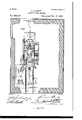
- FIG. 1 represents the motor in elevation and partly in longitu dinall section the general arrangement of a motor with its foundations constructed according to my invention.
- Fig. 2 represents the motor in elevation and the foundations in transverse section.
- Fig. 3 is a plan of the same.
- Fig. 4 represents-the motor in side elevation.
- Fig. 5 represents the motor 1n, longitudinal section.
- Fig. 6 represents the motor and apparatus placed upon the foundation.
- Fig. 7 represents the motor cylinder lpin in position.
- Fig. 8 illustrates the lower portion of the motor cylinder in section on the line A. B. C. D. Fig. 6, showing the connection' between the regenerator and the admis- 55 sion and escape valves.
- Fig. 9 represents the escape valve in section drawn to a larger scale.
- Fig. l0 illustrates the admission valve in end elevation.
- Fig. 11 .represents a side elevation of the same.
- Fig. 12 is alongitudi- 6o nal elevation of the mechanism foi-.working the escape valve.
- Fig. 13 is a longitudinal elevation of the mechanism for working the admission'valve.
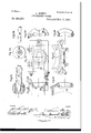
- Fig. 14 represents the stoking or fuel 'supplying apparatus in longitudi- 65 nal elevation.
- Fig. 15 illustrates the same apparatus in endl elevation.
- Fig. 16 illustrates the eccentric shaft of the stoking apparatus drawn on an enlarged scale.
- Fig. 17 represents this shaft in longitudinal ele- 7o Vation.
- Fig. 18 illustrates the exterior of the combustion chamber showing the construction and fastening of the door.
- Fig. 19 represents the combustion chamber in horizontal-section onthe line E F Fig. 18.
- Fig. 75V 2O represents thel'combustion chamber invertical section on the line GII Fig. 19.
- Fig. 2l illustrates vthe combustion chamber in Vertical 'section on the line I J Fig. 19 the swivel or ball and socket arrangement for the stir- 8vo ring instrument being omitted.
- Fig. 22 represents in longitudinal'section the swivel with the endof the stirring instrument or poker.
- Fig. 23 represents the'saine in end elevation.
- Fig. 24 illustrates the shape of the extremity 85 of the poker.
- Fig. 25 is a front elevation of the combustion chamber door the cap or cover of the swivel or socket of the poker being removed.
- Fig. 26 represents the same in transverse section.
- Fig. 27 represents the door in 9o plan.
- Fig. 28 represents the doorin horizoni tal section. ball and socket swivel in vertical section.
- Fig. 30 represents the same in horizontal section.
- Fig. 31 is a longitudinal elevation of 95 the eccentric p in or axis of the cap.
- Fig. 32 illustrates the shape of the extremity 85 of the poker.
- Fig. 25 is a front elevation of the combustion chamber door the cap or cover of the swivel or socket of the poker being removed.
- Fig. 26 represents the same in transverse section.
- Fig. 27 represents the door in 9o plan.
- Fig. 28 represents the door
- Fig. 33 is an end view of the same.
- Fig. 33 isafront View of the door with the cap and eccentric
- Fig. 34 is a transverse section of this combination showing the swivel roo and poker.
- Fig. 35 illustrates this combination in plan without the swivel and poker.V
- Fig. 29 represents the cap of the I Fig. 36 is ahorizontal section showing the position occupied by the ball or swivel arrangement between the door and the cap.
- FIG. 1 to 3 represent the motor proper ixed with its base on the level of the ground upon a foundation in which are arranged an air chamber and an apparatus for heating the compressed air.
- the motor is of the beam engine type.
- the beam marked 1 in the drawings in place of being suspended on a fixed center is supported by astrong vertical arm or rod 2 capable of oscillating on a fixed axis 3 working in bearings on the bed plate 4.
- That arm of the beam which is connected tothe piston'rod is connected at about the middle of its length by two small lateral rods or links 5 totwo pins 6 rigidly attached to the upper part ofthe motor cylinder 7.
- the motor cylinder 7 which is provided at its upperpart with the fixed pins 6 for guiding the beam is firmly fixed in a vertical position being supported laterally by two hollow struts 11 and longitudinally by two stays or inclined legs 12 which enable it to resist the oblique strain which is produced in working the engine and is transmitted tothe cylinder by the links 5.
- the air pump l0 is supplied from a large chamber 13 arranged below the level of the tioor and communicating with the external atmosphere through an underground pipe 14 (Fig. 1).
- This air chamber act-s in ⁇ cover 15 is provided forexamining and cleaning ont the chamber 13.
- the air thus drawn in by the pump passes through the suction valves 16 (Figsp and 6) and delivery valves 17 which may be of any suitable form.
- the delivery valves are arranged above the suction valves in the interior ot' the semicircular gallery 18 cast in one with the air pump cylinder and by which the latter is connected to the chamber 4.
- the air being suitably cooled passes through the circular passage or gallery 18 into the hollow bed plate 4 which forms a reservoir or storage chamber for the compressed air.
- the air proceeding from the chamber 4 passes through a pipe 24 (Fig. l) into a supplementary chamber 25 which it enters through an oritice 26 (Fig. 2).
- This chamber is formed by a cast iron box strengthened by ribs or f webs and arranged in the foundationy of the motor. is received on leaving the chamber 25 is coniposed of a long metal pipe bent in a zig zag or sinuous form the external surfaces of which being'provided with ribs Ain order to increase the heating surface are heated by the exhaust gases which are "discharged from the motor cylinder in a heated condition. By these means the greater part of the heat which has not been expended in doing work by acting upon the motor piston is utilized for the ⁇ preliminary heating of the supply of air.
- the curved metal tube or worm is composed of short lengths of tube 27 (Figs. 2, 3 and 6) in the form of the letter S connected together by tlanges and bolts in such a manner as to form for example threetiers of ten lengths each but I do not limit myself to these numbers.
- These tubes are provided, in addition to the lianges, with projections 28 which when the lengths of the tube are joined together are connected to vertical iron plates by which the three lines of pipe are firmly tied together and are enabled to be lit'ted in one piece.
- the three worms are connected at each end to a suitable collecting pipe.
- the-next' A 'ble elliptical tube 33 is containedina rigid sleeve l34 ofv slightly conical or taperform. 3 5 (Figs. 3 and 6) rigidly attached :to the side of ⁇ the metal'casing .which at-this pointis. perforated as well as the brickwork with'a hole,
- the tube 33 is of sufficient ⁇ length-to enable its iexibility toallow of the expansion ofthe case of the regenerator.
- the ad mission valve' 36 (Figs. 8, 10 and l1) to which the compressed.
- cams 38 (Fig. 13) on thehorizontalshaft. Themo'vementis transmitted ⁇ to thevalve by a combination of rods.
- This :gear is so constructed as toenable a gov-z ernorV-39 (Fig.,4) tocause theroller. 40 to work diminish the'admission of air accordingfto the variations in the speed.
- the apparatus represented The part of this-pipe. immediately vbeyond the bend is flattened or: 25 of elliptical form in section'the major-axis of tion .with the compressed air.
- chamber of the' motor As ,the4 pressure increases/or dimin'y lpasses-through a passage 4l (Fig. 8) at the lower part of the mass offuel containedin the combustion chamber through which it liows thereby becoming largely increasedin volume.
- the second part passes, through the passage/42 over the combustion chamber and' is used for the combustion-of thecarbonic oxide generated.
- Thezcombustion chamber is placed in-p ⁇ o sition by wheelingit under the vcylinder zand attachingit-by means of a tight-joint made as herein-after described.
- Thebottom isl enlargedAor widenedbeing formed by a basin 4G slightly convexat the centerand likewise protected'A by a iireproof Ilining.
- y Alilxternallyrthe lower part of the furnace is provided with'a conical base 47 -formedl in the casting and supported upon four: wheels.
- i The whole structure isv strength" ened by vertical ribs 48 which enable'the com'-4 bustionchamber tosupport a considerable amount of vertical pressure without breaking.
- -The passage41 receiving a portion of the air from'the .admission valve . is formed in castingin'the casing of the combustion chamber. Thisformbf combustionchamber enables the 'fuel to beA burned without agrate.
- ⁇ At thelowerpa'rt 4ofthe combustion chamber there is a door 53 4,enabling the ash-clinkers'or fuel to be removed when required. tightly closed and to vbe capable of :resisting Ithe pressure of thecompre'ssed ai'r inside the .Y A, combustion chamber. at., 37?;Figsf10, and 11 is a weightedpiston in communica ⁇
- the door in place of being fiat is formed with a cylindrical part of the same radius or curvature as the external casing of the combustion chamber to which it is accurately fitted. This door being placed in position is pressed to its seat or bearings on the one hand by a forked bar 50a (Figs.
- the door may be described as being pressed against the cylindrical surface of the combustion chamber in the same way as a belt is pressed against the rim of a pulley and the pressure is uniformly distributed on the joint independently of the way in which the tightening up is. performed.
- the door thus constructed can be employed to obtain access to the combustion chamber only during stoppages of the motor and when there is no pressure in the said chamber. It is also necessary to provide means for loosening from the exterior the mass of clinkers that is formed in the combustion chamber and without stopping the motor as they would otherwise run together under the mass of burning fuel and end by choking up the passage for the air.
- a ball and socket swivel 57 through the axis of which passes a poker or stirring instrument 58 which is consequently capable of lateral motion upon the axis of the said swivel.
- the latter is formed by a ball or sphere working in a corresponding cavity or recess formed in two parts one of which is formed in casting upon the door itself.
- the other part consists of a cast iron cap 59 provided with two lugs 60 perforated with oval holes through which is passed a pin or rotary shaft rotated by means of a handle 61.
- the trunnions 62 (Figs.
- the apparatus is manipulated as follows: Assuming the furnaceto have been charged with fuel (previously to starting the motor) and that the fire consequently does not require stirring the handle 61 (Fig. 33) is placed in a vertical position the ball and poker being in the position represented in Fig. 34. The nuts and washers 66 on the retaining bolt 65 are then permanently tightened up. Sufcient play is allowed at the joints to enable the spherical surfaces to be brought into close contact dur-- ing this tightening operation so that the aperture provided for the passage of the poker is etfectually closed and no leakage of air can take place.
- the center of the disk 69 is supportedupon the center of a strong beam supportedat both ends by bolts 71 suspended from the bed plate 4 of the motor.
- the bearings of these parts are of spherical form and the holes through which the rods or bolts are passed are tapered or conical to allow of oscillation.
- the joint between the ⁇ lower edge of the cylinder and the upper edge of the combustion chamber is packed with a composition of asbestus and plumbago IOO which is powerfully compressed by the thrusting action exerted upon the combustion chamber by the-steel spring disky 69.
- the combustion chamber is enabled to expand freely in a vertical direction without breaking any of the parts the sole'effect of the expansion being to slightly increasey the deflection of the disk 69.' and thus increase the pressure upon the asbestus packing.'
- the motor cylinder is made in two parts.' The lower part72 is linedy with fire clay. Its length is equal to-the stroke of the pistonand it is provided withadmission ports 42 and exhaust ports 73 and with the vopeningthrough which thefuel is introduced (Fig. 5).v Thef upperpart 74 is bored out uand i's cooled by'la water jacket. This second part attached to the first part by bolts is connected to the struts 11 (Fig. 7). On the top of this cylinder 'is bolted a castgiron 'ring carrying the supports of the pin G ⁇ of'the'links 5 (Fig. 7). Thepiston being in .the form of a hollow plunger is made in three Aparts bolted together inthe interior.
- the lower part 75 is ofzcylindroconicalform and its under side lits into the 'conical part 45 of the 'combus-v tion chamber as closely as possible in order to reduce the Waste space but at the same time allowingla certain amount of play when the piston isat the end of its stroke.
- This lower part ofthis piston is exposed to the greatest heat. being in immediate fcontact with the dame and'in order to preserve it from burning or overheating it is ⁇ provided internally withA a suitable number of vertical ribs or webs 76 presentin'galarge surface in contact with the external atmosphere so as to cool' the metal asmuch as possible.
- the metal part 78 of the piston is utilized for rigidly connecting the pistonto its rod which Vengages with a conical socket 79 connected to transverse arms 80.
- This connection does not require to be jointed owing to Vthe peculiar arrange- Ament ofthe main beam hereinbefore described. Y Consequently there is no joint requiring lubrication in the interior of the piston this being an important advantage the temperature at the lower part of the piston being too high to admit of the use of lubricants.
- the two parts 75 and 78 of the piston are of a diameter slightly less than the internal diameter of the cylinder so that they do not rub against thev sides of the latter but leave a narrow annular space Sl between the two cylindrical surfaces.
- the piston is made tight solely by the vthird part or upper section 82 .which is provided with' suitable 'metal packing orjunk rings.
- the piston is made of such a length that when it is at the upper.
- a vertical tube 83 (Fig. 5) closed atv its lower end and moving with the piston'.
- this tube Works another tube84 of smaller diameter which is stationary beingsecured atits'upper part to a bracket 85 bolted to the cast iron, ring on the top of the cylinder.
- This second tube works in glands 86 like the plunger' of a pump and introduces into the first tube a con ⁇ tinual 'supply of compressed air which'is supplied from the air chamber by a pipe 87.
- the interior o'f the tube 83 communicates through a pipe 92 with the groove 91 into whichthe air under pressure is injected. This.
- the apparatus for introducing the 4fuel is arranged upon the motor cylinder.
- This fuel is introduced by hand into the combustion chamber as required by means of the charging or stokingl apparatus illustrated in the general view Fig-5 and in detail drawn'to'a larger scale in Figs. 14 to 17 of-the drawings.
- This stoking or fuel feeding apparatus is con# structed with a hollow cylinder 96 turned and fitting accurately in a half cylinder 97 of cast iron with hollow sides cooled by a currentof water.
- the fuel is placed in a cavity 98 (Fig.
- the exhaust carries with it mechanically a quantity of particles of carbon, of dust and of sparks which would be liable to get between the rubbing surfaces ot' the guides causing them to bind, or stick and would be liable to stop between the valve and its seat so as to prevent it from closing properly.
- the valve proper marked 110 is in the shape of a metal bottle through which al current of cold water is caused to flow it being introduced at the lower part through a vertical pipe at 111 and escaping at the upper part through a pipe 112 after having cooled the sides of the valve.
- the valve is represented as being in the raised or open position.
- the valve In closing it descends and rests upon its seat 113 thus cutting 0E a communication between the space 114 through which the gases are discharged and the exhaust chamber 115.
- the valve is guided by means of two metallic linings made in segments one of which surrounds the lower part of the valve while the other surrounds the upper part which is of smaller diameter and corresponds to the rod in an ordinary valve.
- the lower lining is capable of sliding vertically inthe casing in the same way as the piston of a steam engine and works 1n a cylindrical opening bored out in the valve box and cooled by a current of water circulating at 116.
- the upper lining works .1n a similar manner in a sleeve forming a tight joint with the valve box.
- the valve isbrought down on to its seat by the action of compressed air supplied from the air chamber through a small pipe 117 acting in the space 118 upon the annular shoulder formed by the difference in the diameters of the two parts of the valve.
- a stirrup 119 into which projects one arm of a bell crank lever 120 (Fig. 12) which bears upon the lower extremity of an adjustable screw 121.
- This lever receiving oscillating motion from a cam 122 by the intervention of a connecting rod 123 lifts and opens the exhaust valve and allows it to descend and' close at the required intervals.
- the lift of the valve 110 is equal to one quarter of the diameter of the orifice which it covers or in other words its stroke is made as short as possible.
- the capacity of the space 114 surrounding the valve is also made as small as possible in order to reduce the waste space to a minimum but its shape is designed with a view to guiding the exhaust gases in a most advantageous manner. When the valve is raised the exhaust gases rush through the.
- the lower end only which serves to direct the gaseous current is unprotected but presents a rough surface of cast iron which is continually cooled and is consequently not liable to be injured by the impact of the particles of solid matter. not accumulate upon ⁇ the seat ot the valve which is purposely made very narrow and inclined.
- the continued escape of air entering the space 118 prevents the dust and hot gases from entering the segments and the lower ICO These particles cani Moreover the force required to open the valve.
- the exhaust gases after passing lthe valve- '.110 enter a chamber 115 provided with a re proof lining.
- the hot exhaust gases' are employed for heating the regenerator to which they are conducted by a pipe madeof large Y diameter in order to .present as little resistance'asipossible to the flow of the gases.
- the cast iron exhaust pipe'i'l isprovided at its upper extremity with a ball and socket joint 125 ⁇ working in a socket 126 1 packed withasbestusand bolted to the'under side of the chamber 115.
- this pipe lx works in a stuffing box 127 provided'at its lower part'with a ball and socket joint 12S working inthe same way as 2 the joint'125 in a socket' 129 packed with asbestus and fixed on the cover of the metal casing ofthe regenerator.
- this invention advisable in erectinga motor according tb this invention to provide a tank or reservoir of sufficient capacity to enable the Water heated by the circulation to remainin the tank for a sufficient time to enable it to be cooled before it returns to the motor.
- This tank is not represented in the accompanying drawings but it will be readily understood that it may be arranged inthe same way as lt is consequently' the tanks frequently employed inconnection with ⁇ gas engines.
Landscapes
- Engineering & Computer Science (AREA)
- Mining & Mineral Resources (AREA)
- Chemical & Material Sciences (AREA)
- Combustion & Propulsion (AREA)
- Mechanical Engineering (AREA)
- General Engineering & Computer Science (AREA)
- Mechanically-Actuated Valves (AREA)
Description
(No Model.) 13 Sheets-Sheet 1.
- L. GENT Y. I
ABROTHERMIG MOTOR.
Patented No? 7, 1893.
(No Model.) 13 Sheets-Sheet 2. L GENTY. y
AEROTHERMIG MOTOR. No. 508,301. Patented NOV. 7, 1893.
Wilnesses Invmlor ma coMPANv.
(No Model.) l1e' sheets-sheet '3. L. GENTY.
ABROTHBRMIG MoToR. No. 508,301. Patented NOV. 7, 1893.
(N16 Model.)` 13 sheets-sneer 4. A L. GENTY.
AEROTHERMIG MOTOR.
Ptented Nov. '7
(No Model.) 13 Sheets-Sheet 5.
L. GENTY.
AEROTHBRMIG MOTOR. No. 508,301. Patented Nov. 7, 1893.
Fig, 5.
'me NArloNAL LrrHoaRAr-nma cuMPANY.
wAsumatoN. D. c.
(No Model.) lsheets-sheet l6. L. GEN'TY.
ABROTHERMIG MOTOR.
No. 508,301. Patented Nov. 7, 1893.
Wifzwsses mi@ (No Model.) 13 Sheets-Sheet 7.
L. GENTE?. AEROTHBRMIG MoToR Patented Nov. 7
llwmlar VV buss @s wAsHmGYoN. l:4 c.
(No Model.) 13 Sheets-Sheet 8.
' L. GBNTY.
ABROTHBRMIG MOTOR.V
Patented Nov. 7, 189s.
9. t e e h S S t e e h S 3 1 um. 0 T .O .YM TC Nm ER GE .H LM R E A u d 0 M O m vPatented Nov. '7, 1893.
Inl/miur' THE NAYIDNL LIYHOGPPHING COMPANY.
A NGfON D C (No Model.) 13 sheets-sneen io. L. GENTY.
ABROTHBRMIC MOTOR.
vPajaelclted Nov. 7, 1893.
llllglll .S
Wilnesses (No Model.) 13 Sheets-Sheet 11.
L. GENTY. AEROTHBRMIG MoToR.
No. 508,301. Patented Nov. 7, 1893.
Figl.
Inl/enf@ YHE NArloNAL LmgoaRAPnlNa coMPANv,
wAamNuYoN. u. c.
(No Model.)
No. 508,301. Patented Nov. 7, 1893.
UNITED', STATES "PATENT OFFICE.
lLUCIEN GENTY, or TOURS, FRANCE.
AERoTHl-:RMIC MoToR.
SPECIFICATION forming part of Letters-Patent No. 508,301, dated November 7, 1893.
Application led August 12,1892. Serial No. 442,937. (No model.)
To a/ZZ ,whom it mag/.conc'erm Beit known that I, LUCIEN GENTv, a citi- Zen of France, and a resident of Tours, in the Department of Indre-et-Loire, France, have invented a new and useful Improvement 1n Aerothermic Motors, of which the following is a specification.
My invention has for its object the removal of thedisadvantages which have heretofore Vprevented hot air motors'from coming into capable of withstanding the destructive action of the liame and dust; the employment of a jointed escape pipe admitting of free expansion of the parts, the application of an improved heat regenerator with provision I for expansion, and improvements in the conythe fuel into the combustion chamber.
struction of the apparatusfor introducig .Y means of these several improvements and by combining the same I am enabledto construct a hot air engine capable of being employed with great advantage in' practice; andA 1n order that my-said invention may be fully understood I shall now proceed more particularly to describe the same and for that purpose shall referv to the several figures on the annexed sheets of drawings the same figures of reference indicating corresponding parts in all the ligures. Figure l of the accompanying drawings represents partly in elevation and partly in longitu dinall section the general arrangement of a motor with its foundations constructed according to my invention. Fig. 2 represents the motor in elevation and the foundations in transverse section. Fig. 3 is a plan of the same. Fig. 4 represents-the motor in side elevation. Fig. 5 represents the motor 1n, longitudinal section. Fig. 6 represents the motor and apparatus placed upon the foundation. Fig. 7 represents the motor cylinder lpin in position.
in section. Fig. 8 illustrates the lower portion of the motor cylinder in section on the line A. B. C. D. Fig. 6, showing the connection' between the regenerator and the admis- 55 sion and escape valves. Fig. 9 represents the escape valve in section drawn to a larger scale. Fig. l0illustrates the admission valve in end elevation. Fig. 11 .represents a side elevation of the same. Fig. 12 is alongitudi- 6o nal elevation of the mechanism foi-.working the escape valve. Fig. 13 is a longitudinal elevation of the mechanism for working the admission'valve. Fig. 14 represents the stoking or fuel 'supplying apparatus in longitudi- 65 nal elevation. Fig. 15 illustrates the same apparatus in endl elevation.` Fig. 16 illustrates the eccentric shaft of the stoking apparatus drawn on an enlarged scale. Fig. 17 represents this shaft in longitudinal ele- 7o Vation. Fig. 18 illustrates the exterior of the combustion chamber showing the construction and fastening of the door. Fig. 19 represents the combustion chamber in horizontal-section onthe line E F Fig. 18. Fig. 75V 2O represents thel'combustion chamber invertical section on the line GII Fig. 19. Fig. 2l illustrates vthe combustion chamber in Vertical 'section on the line I J Fig. 19 the swivel or ball and socket arrangement for the stir- 8vo ring instrument being omitted. Fig. 22 represents in longitudinal'section the swivel with the endof the stirring instrument or poker.
Fig. 23 represents the'saine in end elevation. Fig. 24 illustrates the shape of the extremity 85 of the poker. Fig. 25 is a front elevation of the combustion chamber door the cap or cover of the swivel or socket of the poker being removed. Fig. 26 represents the same in transverse section. Fig. 27 represents the door in 9o plan. Fig. 28 represents the doorin horizoni tal section. ball and socket swivel in vertical section. Fig. 30 represents the same in horizontal section. Fig. 31 is a longitudinal elevation of 95 the eccentric p in or axis of the cap. Fig. 32
is an end view of the same. Fig. 33 isafront View of the door with the cap and eccentric Fig. 34 is a transverse section of this combination showing the swivel roo and poker. Fig. 35 illustrates this combination in plan without the swivel and poker.V
Fig. 29 represents the cap of the I Fig. 36 is ahorizontal section showing the position occupied by the ball or swivel arrangement between the door and the cap.
The illustrations of the general arrangement Figs. 1 to 3 represent the motor proper ixed with its base on the level of the ground upon a foundation in which are arranged an air chamber and an apparatus for heating the compressed air. The motor is of the beam engine type. The beam marked 1 in the drawings in place of being suspended on a fixed center is supported by astrong vertical arm or rod 2 capable of oscillating on a fixed axis 3 working in bearings on the bed plate 4. That arm of the beam which is connected tothe piston'rod is connected at about the middle of its length by two small lateral rods or links 5 totwo pins 6 rigidly attached to the upper part ofthe motor cylinder 7. Under these conditions the extremity of the beam is compelled to travel practically in a straight line and the necessity for connecting the beam to the piston by means of a jointed connect ing rod is obviated the jointat the lower end of such connecting rod being diicult to lubricate and keep `in order. This arrangement also obviates the oblique thrust upon the piston which produces vibrations and tends to cause the cylinder to wear oval. The other extremity of the beam is connected to two rods 8 and 9; the rod 8 imparts rotary motion to the horizontal shaft ot' the engine and the rod 9 works an air compressing pump 10. Figs. 4 and 5 illustrate the manner in which the bearings of the horizontal shaft and of the oscillating arm 2 are arranged upon the hollow bed plate 4 which forms a chamber for the compressed air. The motor cylinder 7 which is provided at its upperpart with the fixed pins 6 for guiding the beam is firmly fixed in a vertical position being supported laterally by two hollow struts 11 and longitudinally by two stays or inclined legs 12 which enable it to resist the oblique strain which is produced in working the engine and is transmitted tothe cylinder by the links 5.
By means of this arrangement great strength is imparted to the Whole structure While all the parts are rendered easily accessible.
I= will now proceed to describe one by one the several parts ot the motor to which my improvements relate and in this description I will follow the course ofv the air from the timeiwhen it is drawn infrom the atmosphere until it is discharged from the motor, .describing successively in the orderin which they present themselves the different pieces of mechanism and apparatus met with vor traversed by the said air or gases of combustion in their passage through the motor.
In order to obviate the noise which would beproduced by drawing air direct from the engine house the air pump l0 is supplied from a large chamber 13 arranged below the level of the tioor and communicating with the external atmosphere through an underground pipe 14 (Fig. 1). This air chamber act-s in `cover 15 is provided forexamining and cleaning ont the chamber 13. The air thus drawn in by the pump passes through the suction valves 16 (Figsp and 6) and delivery valves 17 which may be of any suitable form. The delivery valves are arranged above the suction valves in the interior ot' the semicircular gallery 18 cast in one with the air pump cylinder and by which the latter is connected to the chamber 4. The pump cylinder Fig. 5 is provided with a jacket in lwhich water is causedto circulate in order to absorb the heat resulting from the compression ot' the air. The air being suitably cooled passes through the circular passage or gallery 18 into the hollow bed plate 4 which forms a reservoir or storage chamber for the compressed air. The air proceeding from the chamber 4 passes through a pipe 24 (Fig. l) into a supplementary chamber 25 which it enters through an oritice 26 (Fig. 2).
This chamber is formed bya cast iron box strengthened by ribs or f webs and arranged in the foundationy of the motor. is received on leaving the chamber 25 is coniposed of a long metal pipe bent in a zig zag or sinuous form the external surfaces of which being'provided with ribs Ain order to increase the heating surface are heated by the exhaust gases which are "discharged from the motor cylinder in a heated condition. By these means the greater part of the heat which has not been expended in doing work by acting upon the motor piston is utilized for the `preliminary heating of the supply of air.
The curved metal tube or worm is composed of short lengths of tube 27 (Figs. 2, 3 and 6) in the form of the letter S connected together by tlanges and bolts in such a manner as to form for example threetiers of ten lengths each but I do not limit myself to these numbers. These tubes are provided, in addition to the lianges, with projections 28 which when the lengths of the tube are joined together are connected to vertical iron plates by which the three lines of pipe are firmly tied together and are enabled to be lit'ted in one piece. The three worms are connected at each end to a suitable collecting pipe. This combination is inclosed in a cast iron box or casing 29 supported on a fixed point at-the end farthest from the engine being the end least heated by the exhaust gases and supported at its other extremity upon a ball 30 (Figs. 1, 2, 8 and 9) which being capable of rolling on a ilat or slightly concave surface, enables the cast iron box to expand under the influence of the high temperature of the exhaust gases which pass through it being discharged from the motor cylinder through an exhaust pipe 31 (Figs. 2,8 and 9). The special action of this exhaust pipe and its The heat exchanger in which the air' IOO IIO
connection with the box-or casing of there.- generatorfand exhau'st .valve areh'ereinafter more fully described. This casing is protectedinternally by a 4lire-brick lining 32 which 5 preserves it from contactwith the-hot gas and resists the high temperature so thatthe metal sides of the casingare simply required to resist the slight pressure of the exhaust gases and act as a frame or support forrhe firebrick lining. Before it enters the motor cylinder. the compressed air is compelled to trav-V erse the whole length of the worm 27 while ...the flames heat the ribs or webs on the exterior of the worm the said ribs or webs being arranged vertically as represented in the ldrawings (Fig. 2).
It isnecessary to enable thecombination of tubes to expand in lthe regenerator 'without injury to the points infthe interior ofrthe tireproof casing. This expansionis provided'for as follows: The Aair proceeding-from the chamber 2 5 enters the regenerator through a bent pipe 33 (Figsf3and 6.).
the ellipse being vertical and itis then united with the extremity ofthe regenerator atkwhich etheair is 1 supplied. This liattening 'ofthe tube renders itflexible for a sufficient length 3o to enable it to accommodate itself to the elongation of-the series of regenerating pipes.
Throughoutmhe whole of this length the-next' A 'ble elliptical tube 33 is containedina rigid sleeve l34 ofv slightly conical or taperform. 3 5 (Figs. 3 and 6) rigidly attached :to the side of` the metal'casing .which at-this pointis. perforated as well as the brickwork with'a hole,
leavingthe regenerator the compressed air is conducted to. theinlet valve vthrough apipeV 35. The combination of .beuttubes or worms. is attached tothe sides of. the casing at the extremityr'nearest to the exhaust valve andis free lto expandat the otherextremity which'.
' is supportedupon a ball andtis no t connected tothe case except by the flexible tube 33. 5o The tube 33 is of sufficient `length-to enable its iexibility toallow of the expansion ofthe case of the regenerator. The ad mission valve' 36 (Figs. 8, 10 and l1) to which the compressed.
air is su pplied ata relatively low temperature 5 5 through the long pipe 35 is a doublebalanced Valve held to its seat 'by ahelical spring '37.1
and worked by one-ofthe. cams 38 (Fig. 13) on thehorizontalshaft. Themo'vementis transmitted` to thevalve by a combination of rods.
6o and bell crank levers asfillustrated in Fig.13.
This :gear is so constructed as toenable a gov-z ernorV-39 (Fig.,4) tocause theroller. 40 to work diminish the'admission of air accordingfto the variations in the speed.
The apparatus represented The part of this-pipe. immediately vbeyond the bend is flattened or: 25 of elliptical form in section'the major-axis of tion .with the compressed air. chamber of the' motor: As ,the4 pressure increases/or dimin'y lpasses-through a passage 4l (Fig. 8) at the lower part of the mass offuel containedin the combustion chamber through which it liows thereby becoming largely increasedin volume. The second part passes, through the passage/42 over the combustion chamber and' is used for the combustion-of thecarbonic oxide generated. e The combustion .chambery situ-ated atthe lower end of the motorcylinderfisconstructed in such a manner as'to be capable. of being readily 'separated 'or detached-for examination or repairs. .Wit-hthis object it isr placed uponI fourwheels (Figs. 2,1-
18 and 19) traveling upon rails 43Figs..3 and `6. Thezcombustion chamberis placed in-p`o sition by wheelingit under the vcylinder zand attachingit-by means of a tight-joint made as herein-after described.
The combustion 'chamber .44 illustrated-- Adrawn to a larger scale in Figs. 18 'to'2l of-r95 the; annexed drawings is 'ofthe'shapevof'afunnelfofcast iron lined with fire clay45.
Thebottom isl enlargedAor widenedbeing formed by a basin 4G slightly convexat the centerand likewise protected'A by a iireproof Ilining. y Alilxternallyrthe lower part of the furnace is provided with'a conical base 47 -formedl in the casting and supported upon four: wheels. i The whole structure isv strength" ened by vertical ribs 48 which enable'the com'-4 bustionchamber tosupport a considerable amount of vertical pressure without breaking. -The passage41 receiving a portion of the air from'the .admission valve .is formed in castingin'the casing of the combustion chamber. Thisformbf combustionchamber enables the 'fuel to beA burned without agrate.
be continually cooled at the place where it is .exposed to thehighest temperature bywat-er circulating'at'49. The lire proof liningissecured between two movable iron rings 50fand 51 the ring 50 being loosely supported in a gcorresponding recess in the lower part of the*v cast iron casing 44 and thering 51 surroundingthe 'orifice of the funnel being'on'a level with This ldoor requires'fto be The door is made tight vThe lower Apart of the cast iron casing may the edges thereof and to which it is attached by .bol-ts such as the bolt 52 (Fig.` '7)'.- When the .fire proofzlining requires renewal the-upper jring 51is removed and the lining can' then be 'readilyrepairedorremade. `At thelowerpa'rt 4ofthe combustion chamber there is a door 53 4,enabling the ash-clinkers'or fuel to be removed when required. tightly closed and to vbe capable of :resisting Ithe pressure of thecompre'ssed ai'r inside the .Y A, combustion chamber. at., 37?;Figsf10, and 11 is a weightedpiston in communica` The door in place of being fiat is formed with a cylindrical part of the same radius or curvature as the external casing of the combustion chamber to which it is accurately fitted. This door being placed in position is pressed to its seat or bearings on the one hand by a forked bar 50a (Figs. 1S and 19) jointed at one extremity to a iixed lug cast on the outer casing of the combustion chamber and at the other extremity to two lugs 54 on the door. On the other side the door is secured by a strap or stirrup 56 likewise hinged on a fixed lug 56b cast on the external casing and provided with a pressing screw 55 (Fig. 19) which bears against a projection 56 onthe door. By these means the pressures exerted upon the lugs and the projection 56 on the door are always equal and directed in such a manner that the resultant of the said pressures passes through the .center of the area of the door and is normal or perpendicular to the latter. In other words the door may be described as being pressed against the cylindrical surface of the combustion chamber in the same way as a belt is pressed against the rim of a pulley and the pressure is uniformly distributed on the joint independently of the way in which the tightening up is. performed. The door thus constructed can be employed to obtain access to the combustion chamber only during stoppages of the motor and when there is no pressure in the said chamber. It is also necessary to provide means for loosening from the exterior the mass of clinkers that is formed in the combustion chamber and without stopping the motor as they would otherwise run together under the mass of burning fuel and end by choking up the passage for the air. With this object there is provided on the outer side of the door hereinbefore described a ball and socket swivel 57 through the axis of which passes a poker or stirring instrument 58 which is consequently capable of lateral motion upon the axis of the said swivel. The latter is formed by a ball or sphere working in a corresponding cavity or recess formed in two parts one of which is formed in casting upon the door itself. The other part consists of a cast iron cap 59 provided with two lugs 60 perforated with oval holes through which is passed a pin or rotary shaft rotated by means of a handle 61. The trunnions 62 (Figs. 31 and 32) of this shaft work in the two lugs 63 cast on the door but the central part ot' the axis working in two lugs 60 on the cap is eccentric by a few millimeters to the axis of the said trunnions. The lower side of the cap is perforated with a hole (Figs. 33 and 34) through .which passes loosely a retaining bolt 65 (Figs. 26 and 34) provided with nuts and washers 66 and by means of which the cap is connected to the door. By means of these arrangements the swivel or ball 57 can be enabled to rotate freely when the poker is employed for stirring the tire and can be rmly tightened in the position represented in Fig. 34 so as to prevent any escape of air when the poker is not in use. To obtain these results the apparatus is manipulated as follows: Assuming the furnaceto have been charged with fuel (previously to starting the motor) and that the fire consequently does not require stirring the handle 61 (Fig. 33) is placed in a vertical position the ball and poker being in the position represented in Fig. 34. The nuts and washers 66 on the retaining bolt 65 are then permanently tightened up. Sufcient play is allowed at the joints to enable the spherical surfaces to be brought into close contact dur-- ing this tightening operation so that the aperture provided for the passage of the poker is etfectually closed and no leakage of air can take place. In order to work the poker while the parts are thus tightened up, it would be necessary to exert considerable force but by slightly raising the handle 61 rotary motion is imparted to the eccentric pins 62, 64 so as to cause the two lugs 60 to move away from the door. By thus temporarily looseningthe cap the axis of the ball may be caused without great effort to turn in different directions so as to generate a variety of conical surfaces having the center of theball as their apex and these displacements being combined with a sliding or longitudinal movementof the poker in the ball enable the point of this tool to reach all parts of the combustion chamber situated within a field of action determined by cutting away more or less of the hemispherical surfaces between which the ball rotates. The fire being cleared or stirred the poker is raised as represented in Figs. 5 and 34 and the handle 61 is forced down in order to tighten the cap. The poker may then be withdrawn and laid aside. All the parts of the combustion chamber hereinbefore described are supported upon four Wheels (Fig. 19) traveling upon rails 43 (Figs. 2 and 3). In order to place the combustion chamber in position it is placed below the motor cylinder and in the axis of thelatter. When in this position it is immediately over a cast steel disk 69 (Figs. 5 and 7). 'lhe body of this disk is provided with concentric cor,- rugations which impart toit a certain amount of elasticity. The circumference of the disk bears against the under side of the base 47 of the combustion chamber. The center of the disk 69 is supportedupon the center of a strong beam supportedat both ends by bolts 71 suspended from the bed plate 4 of the motor. As indicated in Fig. 7 the bearings of these parts are of spherical form and the holes through which the rods or bolts are passed are tapered or conical to allow of oscillation. When the nut of either of the bolts 7l is tightened powerful pressure is exerted upon the joint between the combustion chamber and the cylinder. In order to enable it to support this pressure which tends to crush it the sides of the combustion chamber are provided with webs 48. The joint between the `lower edge of the cylinder and the upper edge of the combustion chamber is packed with a composition of asbestus and plumbago IOO which is powerfully compressed by the thrusting action exerted upon the combustion chamber by the-steel spring disky 69. By means of this arrangement the combustion chamber is enabled to expand freely in a vertical direction without breaking any of the parts the sole'effect of the expansion being to slightly increasey the deflection of the disk 69.' and thus increase the pressure upon the asbestus packing.'
' The motor cylinder is made in two parts.' The lower part72 is linedy with fire clay. Its length is equal to-the stroke of the pistonand it is provided withadmission ports 42 and exhaust ports 73 and with the vopeningthrough which thefuel is introduced (Fig. 5).v Thef upperpart 74 is bored out uand i's cooled by'la water jacket. This second part attached to the first part by bolts is connected to the struts 11 (Fig. 7). On the top of this cylinder 'is bolted a castgiron 'ring carrying the supports of the pin G` of'the'links 5 (Fig. 7). Thepiston being in .the form of a hollow plunger is made in three Aparts bolted together inthe interior. The lower part 75 is ofzcylindroconicalform and its under side lits into the 'conical part 45 of the 'combus-v tion chamber as closely as possible in order to reduce the Waste space but at the same time allowingla certain amount of play when the piston isat the end of its stroke. This lower part ofthis piston is exposed to the greatest heat. being in immediate fcontact with the dame and'in order to preserve it from burning or overheating it is` provided internally withA a suitable number of vertical ribs or webs 76 presentin'galarge surface in contact with the external atmosphere so as to cool' the metal asmuch as possible. The metal part 78 of the piston is utilized for rigidly connecting the pistonto its rod which Vengages with a conical socket 79 connected to transverse arms 80. This connection does not require to be jointed owing to Vthe peculiar arrange- Ament ofthe main beam hereinbefore described. Y Consequently there is no joint requiring lubrication in the interior of the piston this being an important advantage the temperature at the lower part of the piston being too high to admit of the use of lubricants. The two parts 75 and 78 of the piston are of a diameter slightly less than the internal diameter of the cylinder so that they do not rub against thev sides of the latter but leave a narrow annular space Sl between the two cylindrical surfaces. The piston is made tight solely by the vthird part or upper section 82 .which is provided with' suitable 'metal packing orjunk rings. The piston is made of such a length that when it is at the upper.
part of its stroke the two' lower yparts which are unprovided with packing ll the bored part 74 of the cylinder which is exposed by the ascent of theupper section 82 of the piston. This metal surface is thus Aeffectually protected from direct contact with the llame which wouldl otherwise be liable4 to produce erosions. ln order to further protect this metallic surface cold air may be injected into an annular groove formed above therstsegment. This compressed air tends to escape upwardinto the atmosphere and downward into the combustion'chamber between the piston and the cylinder. This airbeing iunder greater pressure than the pressure in the cylinder andin the combustion chamber itis impossible for the dames and dust to escape between thepiston and the cylinder. .This4 cold air is injected by placing the groove in the piston continuously in connection-with the main compressed air chamber of the) motor by meansof the arrangement hereinafter described. i 1
In the interior of the motor piston there is a vertical tube 83 (Fig. 5) closed atv its lower end and moving with the piston'. In this tube Works another tube84 of smaller diameter which is stationary beingsecured atits'upper part to a bracket 85 bolted to the cast iron, ring on the top of the cylinder. This second tube works in glands 86 like the plunger' of a pump and introduces into the first tube a con` tinual 'supply of compressed air which'is supplied from the air chamber by a pipe 87. The interior o'f the tube 83 communicates through a pipe 92 with the groove 91 into whichthe air under pressure is injected. This. compressed'air iiows into the said groove and into the annular space 81 and clears and cools the sides of the cylinder and of the piston. The water employed for cooling the acting surface of this piston is supplied" through atube provided with iiexible parts made' ofindia rubber andvcarried along the beam. After circulating in the double casing o'r hollow sides of the-piston the water is discharged through a pipe similar to that by which it wasfintroduced. 1
The apparatus for introducing the 4fuel is arranged upon the motor cylinder. This fuel is introduced by hand into the combustion chamber as required by means of the charging or stokingl apparatus illustrated in the general view Fig-5 and in detail drawn'to'a larger scale in Figs. 14 to 17 of-the drawings. This stoking or fuel feeding apparatus is con# structed with a hollow cylinder 96 turned and fitting accurately in a half cylinder 97 of cast iron with hollow sides cooled by a currentof water. In order to introduce a charge offuel into the combustion chamber the fuel is placed in a cavity 98 (Fig. 5) and by means of a crank handle 99 the cylinder 96 is rotated upon its axis through the required angle, so as to invert it and cause the cavity'98 to coincide with an inclined passage under it. Under these cen-V IOO ditions the fuel slides down the incline and The hollow rotary cylinder 96 is 'pressed-to its' semi cylindrical seat 97 by means of thearrangement next hereinafter described. On two fixed centers 102 (Figs. 14 and 15) are pivoted two levers 103 which transmit to the axis or ljournals 104 of the cylinder the pressure which they receive from two rods 105 connected to their extremities by nuts and washers 106. These rods are provided at their other extremity with eyes in which work the eccentric ends 10S (Figs. 16 and 17) ofashaft 107 which acts in exactly the same way as the shaft 62 of the ball and socket joint of the stirrmg mechanism hereinbefore described.
i In other words the angle of the eccentric part 108 relatively to the axis of the handle 109 is so arranged that when this handle is lowered into the vertical position represented in Figs. 14. and 15 it exerts the maximum amount of traction on the rods 105 and the rotary cylinluder 96 of the charging apparatus is powerfully forced down onto its seat 97. In this closed position it is necessary to make a tight joint so that no leakage can take place. This leakage is only prevented by tightening the parts as described which renders it extremely difficult to work the crank 99 so that when it 1s necessary to introduce the charge of fuel the lever handle 109 must be lifted. The rotary motion thus imparted to the shaft 107 and to the eccentric ends 1081oosens slightly the rods 105 and enables the journals 104 of the charging cylinder 96 to rotate freely in their bearings. When the fuel has been introduced and the cylinder brought back to the closed position the parts are tightened up by lowering the handle 109. The gases after acting on the motor piston are discharged into the casing 29 of the regenerator through a valve which is opened by a motor at the re quired intervals. The construction of a durable valve for this purpose presents peculiar difculties. The exhaust valve must always ft perfectly tight. During the exhaust it is exposed to a kind of blow pipe jet which would very rapidly burn and destroy an ordinary gas valve. Moreover the exhaust carries with it mechanically a quantity of particles of carbon, of dust and of sparks which would be liable to get between the rubbing surfaces ot' the guides causing them to bind, or stick and would be liable to stop between the valve and its seat so as to prevent it from closing properly. These disadvantages are obviated by constructing the exhaust valve of the improved motor as illustrated in detail in Fig. 9 of the accompanyingdrawings. The valve proper marked 110 is in the shape of a metal bottle through which al current of cold water is caused to flow it being introduced at the lower part through a vertical pipe at 111 and escaping at the upper part through a pipe 112 after having cooled the sides of the valve. In Fig. 9 the valve is represented as being in the raised or open position. In closing it descends and rests upon its seat 113 thus cutting 0E a communication between the space 114 through which the gases are discharged and the exhaust chamber 115. The valve is guided by means of two metallic linings made in segments one of which surrounds the lower part of the valve while the other surrounds the upper part which is of smaller diameter and corresponds to the rod in an ordinary valve. The lower lining is capable of sliding vertically inthe casing in the same way as the piston of a steam engine and works 1n a cylindrical opening bored out in the valve box and cooled by a current of water circulating at 116. The upper lining works .1n a similar manner in a sleeve forming a tight joint with the valve box. The valve isbrought down on to its seat by the action of compressed air supplied from the air chamber through a small pipe 117 acting in the space 118 upon the annular shoulder formed by the difference in the diameters of the two parts of the valve. At the upper part of this valve there is fixed a stirrup 119 into which projects one arm of a bell crank lever 120 (Fig. 12) which bears upon the lower extremity of an adjustable screw 121. This lever receiving oscillating motion from a cam 122 by the intervention of a connecting rod 123 lifts and opens the exhaust valve and allows it to descend and' close at the required intervals. The lift of the valve 110 is equal to one quarter of the diameter of the orifice which it covers or in other words its stroke is made as short as possible. The capacity of the space 114 surrounding the valve is also made as small as possible in order to reduce the waste space to a minimum but its shape is designed with a view to guiding the exhaust gases in a most advantageous manner. When the valve is raised the exhaust gases rush through the.
port 73 and are divided into two lateral currents by a spur or projection 124. Each of these currents being caused to flow around half the circumference of the valve the area of the vertical section of the two halves of the annular passage 114 being symmetrical relatively to the plane of section in Fig. 9 must diminish according to the same law as the number of streams of gas traversing the said sectionthat is to say, in proportion to the distance traversed in the half circumferences so as to reach a minimum at 114. The exhaust gases draw with them into the passage 114 a stream of sparks which in time would injure the valve 110. This injury is not produced owing to the valve being drawn up into the lower section of the guiding cylinder where it is protected from the flame and dust during the whole of the period of the exhaust. The lower end only which serves to direct the gaseous current is unprotected but presents a rough surface of cast iron which is continually cooled and is consequently not liable to be injured by the impact of the particles of solid matter. not accumulate upon `the seat ot the valve which is purposely made very narrow and inclined. The continued escape of air entering the space 118 prevents the dust and hot gases from entering the segments and the lower ICO These particles cani Moreover the force required to open the valve.
part of the valve guides. This escape of airconstitutes a species 'of protecting sheath Varou nd the valve especially during the ascent -to a minimum'thisV arrangement of the exhaust Valve presents the following advantages namely: No counter spring is required and the .valve guides are easily lubricated not being liable to become` choked with dust.
is alwaysequalto the pressure exerted in the annular space due to' the difference in the diameters of the two fitted parts forming thek guides; 'This force is independent of the pressure existing in the cylinder'at the end of the stroke. It does not cease suddenly at the moment of opening the valve as in an ordi-` nary valveA constructed witha rod or stem.
The details of Vthe constructionand work- I- ing of the exhaust valve have been described at considerable length because theyare of the utmost importance with regard to the working of the motor in practice.
The exhaust gases after passing lthe valve- '.110 enter a chamber 115 provided with a re proof lining. As stated at the commencement of this description the hot exhaust gases' are employed for heating the regenerator to which they are conducted by a pipe madeof large Y diameter in order to .present as little resistance'asipossible to the flow of the gases. If the chamber 115 and the casing-29 of the regenerator were simply connected by a rigid pipe with rigid joints all this part of the mo- 'tor would beliable to be dislocated in working owing to the relative displacements and Vunequalgex-pansion caused by the change of temperature of the different parts; This dis` advantage'is obviated by constructing the connecting pipe .with joints soarra-nged as to provide for the relative displacement in any direction of the chamber. 1115 relatively to the generator 29 and at the same time to enable the pipe tol expand in the direction of its length without tending to separate these two parts of thermotor.' In'order to obtain these two results the cast iron exhaust pipe'i'l" isprovided at its upper extremity with a ball and socket joint 125` working in a socket 126 1 packed withasbestusand bolted to the'under side of the chamber 115. At its lower extremity this pipe lxworks in a stuffing box 127 provided'at its lower part'with a ball and socket joint 12S working inthe same way as 2 the joint'125 in a socket' 129 packed with asbestus and fixed on the cover of the metal casing ofthe regenerator. Under thesecon` ditions when the chamber 115 and the regenerator are displaced relatively to one another 1 the ball and socket jointsv125 and 128 turn in their packedsockets and the tube 31 is also free. to expand and .contract in the direction' of its length byv sliding in the stuffing box127. This tube is protected internally byl a re '.ing of the'regenerator in the opposite direction to the'compressed air flowing in the cast iron pipe or worm.` lThis circulation in opposite directions is highly favorable to the exchange of heat.
It has been shown that a great number of the parts ofthe improved aerothermic motor are cooledbya circulation of water. One of 'the chief advantages of this class of motor is that' they do not consume this liquid being worked solely by the fuel and air.
It is consequently advantageous in places where water is scarce to enable the same quantity of water to circulate continually for cooling the parts loss from leakage being made good from time to time. advisable in erectinga motor according tb this invention to provide a tank or reservoir of sufficient capacity to enable the Water heated by the circulation to remainin the tank for a sufficient time to enable it to be cooled before it returns to the motor. This tank is not represented in the accompanying drawings but it will be readily understood that it may be arranged inthe same way as lt is consequently' the tanks frequently employed inconnection with` gas engines.
The invention is not limited as to the forms,
dimensions, proportions and details 'of'construction illustrated b y way of example in the accompanying drawings.
Having now particularly described and as certained the nature of my saidlinvention and in what mannerthe same is to be performed` IIC '1; In an aerothermic motor, the combina' tion with a motor-cylinder and a movable combustion chamber, of means for tixing'the cylinder of lthe same diameter as the valveseat,'a smaller cylinder arranged above' the rst named cylinder and separated therefrom so as to leave an annular space, and a hollow' valvemovable infsaid cylinders, means for admitting waterto saidhollow valve, and
means for admitting compressed air to the annular space between the two cylinders, substantially as described. v
Publications (1)
| Publication Number | Publication Date |
|---|---|
| US508301A true US508301A (en) | 1893-11-07 |
Family
ID=2577131
Family Applications (1)
| Application Number | Title | Priority Date | Filing Date |
|---|---|---|---|
| US508301D Expired - Lifetime US508301A (en) | L genty |
Country Status (1)
| Country | Link |
|---|---|
| US (1) | US508301A (en) |
-
0
- US US508301D patent/US508301A/en not_active Expired - Lifetime
Similar Documents
| Publication | Publication Date | Title |
|---|---|---|
| US4144902A (en) | Isolation valve | |
| US334153A (en) | George h | |
| US508301A (en) | L genty | |
| US1738890A (en) | Steam-superheating plant | |
| US1924188A (en) | Rotary valve for internal combustion engines | |
| US3751220A (en) | Fluid delivery system for rotary kiln | |
| US2048446A (en) | Steam boiler and fluid heater | |
| US289482A (en) | Peters | |
| US933080A (en) | Heat-engine plant. | |
| US507989A (en) | Petroleum motor | |
| US1266270A (en) | Gas-engine. | |
| US510506A (en) | Combination-valve connection for water-gas apparatus | |
| US1327495A (en) | Gas-producer for propelling vehicles | |
| US733339A (en) | Draft-producing device. | |
| US1593855A (en) | Hot valve for gas-making apparatus | |
| US325640A (en) | Hot-air engine | |
| RU2095587C1 (en) | Gas producer tractor | |
| US309163A (en) | Insom | |
| US387063A (en) | qentt | |
| US1121957A (en) | Melting-furnace. | |
| US365395A (en) | Gas-furnace | |
| US224772A (en) | Thomas m | |
| US227120A (en) | Metallurgic furnace | |
| US710370A (en) | Method of producing draft. | |
| US1732911A (en) | Valve mechanism for internal-combustion engines |