US5067762A - Non-contact conveying device - Google Patents
Non-contact conveying device Download PDFInfo
- Publication number
- US5067762A US5067762A US07/343,344 US34334489A US5067762A US 5067762 A US5067762 A US 5067762A US 34334489 A US34334489 A US 34334489A US 5067762 A US5067762 A US 5067762A
- Authority
- US
- United States
- Prior art keywords
- operating surface
- cushion
- article
- pick
- head
- Prior art date
- Legal status (The legal status is an assumption and is not a legal conclusion. Google has not performed a legal analysis and makes no representation as to the accuracy of the status listed.)
- Expired - Lifetime
Links
Images


Classifications
-
- B—PERFORMING OPERATIONS; TRANSPORTING
- B25—HAND TOOLS; PORTABLE POWER-DRIVEN TOOLS; MANIPULATORS
- B25J—MANIPULATORS; CHAMBERS PROVIDED WITH MANIPULATION DEVICES
- B25J15/00—Gripping heads and other end effectors
- B25J15/06—Gripping heads and other end effectors with vacuum or magnetic holding means
- B25J15/0616—Gripping heads and other end effectors with vacuum or magnetic holding means with vacuum
-
- B—PERFORMING OPERATIONS; TRANSPORTING
- B65—CONVEYING; PACKING; STORING; HANDLING THIN OR FILAMENTARY MATERIAL
- B65G—TRANSPORT OR STORAGE DEVICES, e.g. CONVEYORS FOR LOADING OR TIPPING, SHOP CONVEYOR SYSTEMS OR PNEUMATIC TUBE CONVEYORS
- B65G47/00—Article or material-handling devices associated with conveyors; Methods employing such devices
- B65G47/74—Feeding, transfer, or discharging devices of particular kinds or types
- B65G47/90—Devices for picking-up and depositing articles or materials
- B65G47/91—Devices for picking-up and depositing articles or materials incorporating pneumatic, e.g. suction, grippers
- B65G47/911—Devices for picking-up and depositing articles or materials incorporating pneumatic, e.g. suction, grippers with air blasts producing partial vacuum
-
- H—ELECTRICITY
- H10—SEMICONDUCTOR DEVICES; ELECTRIC SOLID-STATE DEVICES NOT OTHERWISE PROVIDED FOR
- H10P—GENERIC PROCESSES OR APPARATUS FOR THE MANUFACTURE OR TREATMENT OF DEVICES COVERED BY CLASS H10
- H10P72/00—Handling or holding of wafers, substrates or devices during manufacture or treatment thereof
- H10P72/70—Handling or holding of wafers, substrates or devices during manufacture or treatment thereof for supporting or gripping
- H10P72/78—Handling or holding of wafers, substrates or devices during manufacture or treatment thereof for supporting or gripping using vacuum or suction, e.g. Bernoulli chucks
Definitions
- the present invention relates to a non-contact conveying device for lifting up articles without physical contact with the articles by utilizing a gaseous medium such as air.
- this invention relates to a device utilizing ejector effect and Bernoulli effect to lift up articles, as well as hovercraft effect and gas flow cushion effect to prevent injurious contact to the surface of the device.
- gaseous medium such as air to support and/or lift articles
- a gaseous medium such as air to support and/or lift articles
- suction such as a vacuum or a negative pressure source
- a vacuum device is undesirable because physical contact between articles and a pickup device makes the articles susceptible to contamination and/or damage.
- the devices are constructed with a gas-flow boundary surface arranged adjacent the article that is to be picked up, such as a semiconductor wafer.
- a nozzle coupled to a positive pressure gas supply is formed in the middle of the flow boundary surface.
- the velocity of the air flow is increased as it leaves the nozzle and consequently the pressure adjacent the flow boundary surface will be decreased. So, therefore, if the flow boundary surface is placed near a complimentary surface of an article to be picked up, the pressure between them will be sufficient to cause the article to be moved toward the flow boundary surface and thereby be picked up. At the same time, the flowing air provides a cushion to prevent damaging contact of the article with the surface of the device.
- the non-contact conveying device of this invention utilizes not only ejector effects and Bernoulli effects to pick up articles, but also hovercraft effects and gas flow cushion effects to prevent the damaging contact.
- U.S. Pat. No. 4,474,397 utilizes a suction force by an aspirator jet caused by exhaust gas. But, it has none of the Bernoulli effect, hovercraft and gas flow cushion effect.
- a pickup head of the IBM Technical Disclosure Bulletin of September, 1976 (Vol. 19, No. 4) has a downwardly opening chamber having a downwardly inclined inner surface wherein the article exists at the bottom thereof, and a vertically extending inlet nozzle as shown in FIG. 26(b).
- FIG. 26(a) shows the pickup head of the present invention.
- FIG. 26(c) shows a graph of the relationship between the pressure caused on the surface of an article and the distance from the center of the pickup head, wherein P is the pressure caused on the surface of an article and Po is the pressure of the positive gas supply. It can be seen that the maximum negative pressure ratio P/Po of the present invention is about -1.5.
- the maximum negative pressure P/Po of the pick up head of the IBM device is -0.6 and is substantially smaller than that of the invention.
- the ratio P/Po of the IBM device is similiar to that of the prior pickup head of the Bernoulli type utilizing only the Bernoulli effect and gas flow cushion shown in FIG. 5. It is recognized that, in the IBM pickup head having a downwardly inclined inner slope, the only way of lifting the article is by means of the Bernoulli effect which is caused by the reduced static pressure produced by gaseous flow in the narrow space formed between the pickup head and the upper surface of the article, the same as the ordinary prior art shown in FIG. 5. Thus, the narrow space formed between the article and the pickup head of the IBM device does not work as a cushion-vacuum room.
- a diameter of the article should be larger than that of the Bernoulli Part which is the lowest part of the operating surface.
- the outer surface of the article is positioned near the inclined inner slope of the pickup head, that is, the opening chamber of IBM pickup head is not the cushion-vacuum room.
- the gas flow will flow smoothly in the clearance between the article and the Bernoulli part, and accordingly, Bernoulli effect is effective, and the ejector effect in the cushion-vacuum room becomes larger because of the effective Bernoulli effect.
- the pickup heads of British Patent No. 1,054,966 produce only a Bernoulli action which is caused by a reduced static Pressure by conducting a current of gas through a gap between the device and a surface of the article.
- a deflecting element is disposed to attain the highest possible jet velocity in the passage to decrease the resistance of flow from the conduit into the passage Russian Patent No. 1,151,497 lifts an article by a reduced static pressure due to Bernoulli effect.
- the non-contact conveying device of this invention utilizes not only ejector effect and Bernoulli effect to lift articles, but also hovercraft effect and gas flow cushion effect to prevent injurious contact of articles with the surface of the device.
- a non-contact conveying device having two kinds of functions. One function is to lift up articles due to ejector effect and Bernoulli effect and the other function is to prevent contact between the non-contact conveying device and articles due to both hovercraft effect and gas flow cushion effect.
- the non-contact conveying device of the present invention has a pickup head which has an upper wall and a side wall surrounding the upper wall.
- the upper wall and the side wall form a cushion-vacuum room which is fully opened at the bottom of the pickup head.
- the pickup head has an ejector opening which is disposed approximately at the center of the upper wall of the pickup head communicating with the cushion-vacuum room.
- the ejector opening is adapted to be connected to a positive pressure gas supply and the diameter of the ejector opening is smaller than that of the cushion-vacuum room.
- An operating surface adjacent to an article to be lifted is formed at the bottom of the side wall of the Pickup head and the operating surface has a Bernoulli surface defined as the lowest part of the operating surface. The diameter of the Bernoulli surface is smaller than that of the article to be lifted.
- the gas flow enters through the ejector opening into the cushion-vacuum room and discharges outside passing through a space formed between the operating surface and the article.
- the non-contact conveying device operates as an ejector.
- the pressure within the cushion-vacuum room of the pickup head is decreased by ejector effect and the pressure at the space existing between the Bernoulli surface of the pickup head and the article is decreased due to Bernoulli effect of the increased velocity of the gas flow Passing through the narrow space between them, whereby the article is picked up by the pickup head.
- the Bernoulli part When a small clearance is formed between the Bernoulli surface and the article, the Bernoulli part has the function of a gas flow cushion effect and the cushion-vacuum room of the pickup head operates as a pressure room of a hovercraft. The pressure within the cushion-vacuum room due to the pressure rise balances with the suction effect.
- An object of the present invention is to provide a non-contact conveying device to lift and/or support articles.
- Another object of the present invention is to Provide a non-contact conveying device that has a Plurality of individual cushion-vacuum rooms.
- Still another object of the present invention is to provide a non-contact conveying device that has a guide means to prevent lateral movement of articles.
- a further object of the present invention is to Provide a non-contact conveying device having a hood equipped with a suction pipe.
- a further object of the present invention is to Provide a non-contact conveying system that has a moving means and a non-contact conveying device attached at said moving means.
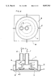
- FIG. 1 is a top plan view of a preferred embodiment of the present invention
- FIG. 2 is a partial sectional side view of the Preferred embodiment shown in FIG. 1;
- FIG. 3 is an explanatory diagram of an ejector
- FIG. 4 shows a graph of the relationship of the pressure to the distance from the center of the non-contact conveying device of the present invention
- FIG. 5 shows a graph of a Bernoulli type pickup head of the prior art
- FIG. 6 shows a top Plan view of another embodiment of the present invention.
- FIG. 7 shows a partial sectional side view of the embodiment of the Present invention shown in FIG. 6;
- FIGS. 8 and 9 show a further embodiment of the present invention, in a top plan view and a partial sectional side view, respectively;
- FIGS. 10 and 11 show still another embodiment of the present invention, in a top plan view and a side view, respectively;
- FIGS. 12 and 13 show a still further embodiment of the present invention, in a top plan view and a sectional side view, respectively;
- FIG. 14 shows a further embodiment of the present invention, in a side view
- FIG. 15 shows still a further embodiment of the present invention, in a partial sectional side view and FIG. 16 shows a bottom Plan view of the embodiment of the present invention shown in FIG. 15;
- FIG. 17 shows a further embodiment of the present invention, in a partial sectional side view
- FIGS. 18 and 19 are each a bottom plan view of further embodiments of the present invention.
- FIGS. 20, 21, 22, and 23 are partial sectional views of still further embodiment of the present invention.
- FIGS. 24(a) through 24(d) show various examples of operating surfaces on a pickup head corresponding to FIGS. 24-23 and FIG. 24(e) shows a graph of the relationship of the pressure to the distance from the center of the non-contact conveying device of another embodiment of the present invention
- FIG. 25 is a perspective view of still another embodiment of the present invention.
- FIG. 25(a) is an explanatory diagram of the present invention
- FIG. 26(b) a prior art device
- FIG. 26(c) shows a relationship between the pressure caused on the surface of an article and the distance form the center of the pickup head.
- the non-contact conveying device A has a pickup head 1 which has an upper wall 5 and a side wall 6 surrounding the upper wall 5, the upper wall 5 and the side wall 6 forming a cushion-vacuum room 2 therein fully opened at the bottom of the pickup head 1.
- An ejector opening 7 is disposed approximately at the center of the upper wall 5 communicating with the cushion-vacuum room 2.
- the ejector opening 7 is adapted to be connected to a positive pressure gas supply (not shown) and the diameter of it is smaller than that of the cushion-vacuum room 2.
- An operating surface 3 having a Bernoulli surface 4 is formed at the bottom of the side wall 6 of the pickup head 1.
- the operating surface 3 is adjacent to an article to be lifted.
- the Bernoulli surface 4 is defined as the lowest part of the operating surface 3 surrounding the cushionvacuum room 2.
- the Bernoulli surface is defined as the most inner part near the cushion-vacuum room 2.
- the ejector opening 7 extends vertically towards the flat operating surface 3 in which the Bernoulli surface 4 exists and the diameter of the Bernoulli surface 4 is smaller than that of the article B.
- the operating surface 3 is round shaped in the vertical section including the axis of the ejector opening 7 in the embodiment shown in FIG. 2.
- the operating surface may be formed in other various shapes, such as flat or conical shaped as shown in FIGS. 14, 15, 17, 23, and 24 conical shaped as shown in FIGS. 20, 21, and 22 and curved shaped shown in FIGS. 2, 7, 9, and 10.
- a gas flow indicated by arrow C into the cushion-vacuum room 2 from the ejector opening 7 passes through a space 8 formed between the operating surface 3 and the article B and discharges outside.
- the non-contact conveying device A utilizes two types of suction effects to pick up and/or support the article B. One is an ejector effect and the other is a Bernoulli effect.
- FIG. 3 an explanatory diagram of the function is shown.
- the cushion-vacuum room 2 of the pickup head 1 operates as a vacuum room a of an ejector
- the ejector opening 7 of the non-contact conveying device A operates as a nozzle b of the ejector
- the space 8 between the operating surface 3 and the article B operates as a diffuser c of the ejector.
- the gas flow indicated by arrow C is jetted from nozzle b into a mixing room d and thereafter passes through the diffuser and discharges outside. During the flow of the gas, a suction power is applied to vacuum room and the pressure of the vacuum room a is decreased.
- the gas flow indicated by arrow C into the cushion-vacuum room 2 from the ejector opening 7 thereafter passes through the space 8 existing between the operating surface 3 and the article B at a high velocity and discharges outside resulting in the pressure of the cushion-vacuum room 2 being decreased by the ejector effect.
- the velocity of the gas flow passing through the narrowest space 8a existing between the Bernoulli surface 4 of the operating surface 3 and the article B is increased and thereby the pressure of the space 8a is decreased by the Bernoulli effect.
- the diameter of the Bernoulli surface 4 which surrounds the cushion-vacuum room 2 should be smaller than that of the article B.
- the article B is picked up by decreased pressure both in the cushion-vacuum room 2 and at the space 8a owing to the ejector effect and Bernoulli effect.
- the pressure decrease is also much larger than that of the prior art having no cushion-vacuum room as shown in FIGS. 5 and 26.
- FIG. 4 shows the graph of the relationship between the pressure caused by the gas flow indicated by arrow C and the distance r from the center of the non-contact conveying device A at the parameter h/D.
- FIG. 5 shows a Bernoulli pickup head of the prior art at the parameter h/d.
- the pickup power of the present invention results from both ejector effect and Bernoulli effect and the parting power is caused by hovercraft effect and gas flow cushion effect.
- the pickup power results only from the Bernoulli effect and the parting power is caused only by gas flow cushion effect.
- the outer inclined portion outside of the Bernoulli surface 4 may act as a diffuser which makes the gas flow smooth.
- the maximum pickup power of the non-contact conveying device A is 2.5 times larger than that of the Bernoulli type pickup head of the prior art.
- the non-contact conveying device A has a parting power 1.3 times larger than that of the Bernoulli type pickup head of the prior art.
- the non-contact conveying device A is superior to the prior Bernoulli type pickup head of the prior art in performance.
- the cushion-vacuum room 2 is divided into a plurality of cushion-vacuum room portion 2a, 2b, 2c . . . by walls 9.
- the walls 9 are disposed radially from the center of the cushion-vacuum room 2. Therefore, the cushion-vacuum room portions 2a, 2b, 2c, . . .
- each cushion-vacuum room portion 2a, 2b, 2c based on clearance existing between each portion 2a, 2b, 2c,. . . and the article B is also independent of each other.
- the clearance between cushion-vacuum room portion 2a and article B may momentarily become small during transient movement and the article during the lifting operation, it results in the pressure within cushion-vacuum room portion 2a being increased.
- the increased positive pressure increases the parting power preventing undesirable contact of the article with a portion of operating surface adjacent the cushion-vacuum room portion 2a.
- the increased pressure in the room portion 2a forces away the article B to a distance where the action forces exerted are at an equilibrium with to the suction forces. That is, the balance will be kept at the Position as if there is a cushion effect. Thus, the article B does not touch the operating surface 2/3 and is lifted up at large clearances thereby reaching an equilibrium position.
- an inner portion of the walls may extend to the center as shown in FIGS. 6 and 7, or may terminate in the cushion-vacuum room 2 as shown in FIGS. 8 and 9.
- FIGS. 10 and 11 show still another embodiment of the present invention which is provided with guide means 10 to prevent lateral movement of the article B being picked up.
- the guide means 10 allows a transfer of the article B from a first position to a second position by moving means, by such a robot R as shown in FIG. 25.
- the guide means 10 comprises a plurality of bars extending radially and having stoppers extending below the plane in which the Bernoulli surface 4 exists. Also, some bars 10a may have steps 10b to contacts certain parts of the surface of the article B where contact is acceptable. The article B is prevented from lateral movement and can be placed at a desired position.
- FIGS. 12 and 13 show a further embodiment of the present invention which is used in a high class clean room.
- the aforementioned non-contact conveying devices A are difficult to utilize in a high class clean room, since the air exhausted from the non-contact conveying device A may contaminate and/or disturb air flow in the clean room.
- gas flow indicated by arrow C is jetted into the cushion-vacuum room 2 from the ejector opening 7 and thereafter passes through a space formed between the operating surface 413 and the article B, and is exhausted outside as an exhaust gas flow indicated by arrow G. If the exhaust gas flow indicated by arrow G discharges into the clean room, it contaminates and/or disturbs the air flow of the clean room.
- the device of the embodiment is provided with a hood 11 enclosing the outer periphery of the pickup head with a gap g.
- the gap g is communicating with a gas suction apparatus (not shown) through the Pipe 12 and the hood 11.
- the exhaust gas flow indicated by arrow G is suctioned as shown by arrow F through the gap into the gas suction apparatus, and it prevents the exhaust gas from being discharged into the clean room.
- a gas flow indicated by arrow F is continuous with the gas flow indicated by arrow G and gas flow indicated by arrow H suctioned from the clean room.
- the quantity of the gas flow indicated by arrow H is to be approximately 20% of that of the exhaust gas flow indicated by arrow G.
- FIG. 14 shows another embodiment of the present invention which has a flat shaped operating surface 513 at a bottom of said pickup head 1.
- the flat shaped operating surface 513 increases gas flow cushion effect caused at the space between the operating surface 513 and an article B.
- the Bernoulli surface 514 is defined as the innermost portion of the flat operating surface 513.
- FIGS. 15 and 16 show another embodiment of the invention being formed with a groove 13 at the operating surface 613 running along the inner surface of the cushion-vacuum room 2.
- the groove 13 may be continuous as shown in FIG. 16 or may be intermittent as shown in FIG. 19.
- the figure of the section of the groove 13 may be rectangular as shown in FIG. 15, or may be triangular as shown in FIG. 17.
- a Plurality of the grooves 13 may be available as shown in FIGS. 15, 16, 17, and 19.
- FIG. 18 shows an example wherein the groove 13 is formed by setting a plurality of small round groove portions 13a.
- FIGS. 20, 21, 22, and 23 show another example of the operating surface 213. In the case of FIG.
- the operating surface 913 has a conical portion 913a throughout the full width in the section including the center axis of the pickup head 1.
- the operating surface 914 of the pickup head of FIG. 21 has a conical portion 914a at the outer region and flat portion 914b at the inner region.
- the operating surface 915 of FIG. 22 has a flat portion 915b at the outer region and a conical portion 915a at the inner region.
- the operating surface 916 of FIG. 23 is flat throughout the full width.
- FIG. 23 corresponds to FIG. 24(a)
- FIG. 21 corresponds to FIG. 24(b)
- FIG. 20 corresponds to FIG. 24(c)
- FIG. 22 corresponds to FIG. 24(d).
- the operating surface 3 may be in various forms including circular, noncircular, conical and flat.
- FIG. 24(e) shows the negative pressure distributions in case of the pickup head shown in FIGS. 20, 21, 22, and 23.
- h/D is defined concerning FIG. 4 is 0.02.
- FIG. 25 shows a non-contact conveying system of the invention, using a non-contact conveying device A of the invention, which can convey a work B to a predetermined place without contacting the work.
- This non-contact conveying system for example, consists of a conveying equipment 17, movement means R having a working arm 19 equipped with a non-contact conveying device A and sensors 21 and 21' which sense a work B and open or shut a solenoid valve 20 between an ejector opening 7 and a blower 18.
- the arm 19 can rotate and go up and down.
- the movement means a robot R in this case, may have electrical motors, air, oil cylinders, etc.
- the conveying equipment 17 may be conveyors, elevators, etc. Another machine, such as inspecting machines, are also available.
- the working arm 19 having the non-contact conveying device A comes down above the work B.
- the solenoid valve 20 is opened, air from the blower 18 is sent from the ejector opening 7 into the non-contact conveying device A and the work B is hung up by the non-contact conveying device A.
- the movement means 16 rises up and turns. Coming above the stock table 22, the movement means stops, and then the solenoid valve 20 is closed. The work B is released from the non-contact conveying device A and placed on the stock table 22.
- the movement means 16 after having parted the work B returns to the conveying equipment 17 again.
- the work B conveyed by the conveying equipment 17 can be placed at the stock table 22.
Landscapes
- Engineering & Computer Science (AREA)
- Mechanical Engineering (AREA)
- Robotics (AREA)
- Container, Conveyance, Adherence, Positioning, Of Wafer (AREA)
- Manipulator (AREA)
Abstract
A non-contact conveying device for lifting and/or supporting wafer-like articles without physical contact with the articles. The device has a pickup head with a cuhsion-vacuum room fully opened at its bottom and has an ejector opening located at the center of its upper wall and communicating with the cushion-vacuum room of the pickup head. The ejector opening is coupled to a positive pressure gas supply. The pickup head has an operating surface at the bottom of the side wall which is positioned adjacnet to an article to be lifted. In the case of a wide clearance existing between the operating surface and the article, the non-contact conveying device works as an ejector and the pressure within the cushion-vacuum room is decreased since the cushion-vacuum room acts in the manner of a vacuum room of an ejector and the space formed between the operating surface and the article acts in the manner of a diffuser of an ejector. In the case of a small clearance existing between the cushion-vacuum room and the article, the non-contact conveying device operates like a hovercraft and the pressure with the cushion-vacuum room increases, since the cushion-vacuum room acts in manner of a pressure room of a hovercraft.
Description
This application is a continuation-in-part of application Ser. No. 07/103,361 filed on Oct. 1, 1987, now abandoned, which is a continuation-in-part of application Ser. No. 07/003,254 filed on Jan. 14, 1987, now abandoned, which is a continuation of application Ser. NO. 06/875,712 filed on June 18, 1986, now abandoned.
1. Field of the invention
The present invention relates to a non-contact conveying device for lifting up articles without physical contact with the articles by utilizing a gaseous medium such as air. Specifically, this invention relates to a device utilizing ejector effect and Bernoulli effect to lift up articles, as well as hovercraft effect and gas flow cushion effect to prevent injurious contact to the surface of the device.
2. Description of the Prior Art
The use of a gaseous medium such as air to support and/or lift articles is well known in the art and includes, for example, such devices as pickup heads and air truck systems.
In certain devices, suction, such as a vacuum or a negative pressure source, is employed to lift and/or support the articles. However, in many applications, for example processing and handling of semiconductor wafers, the use of a vacuum device is undesirable because physical contact between articles and a pickup device makes the articles susceptible to contamination and/or damage.
Other devices which use a positive pressure source to lift or support an article are of the so-called Bernoulli type.
Examples of Bernoulli type pickup head are disclosed in U.S. Pat. Nos. 3,438,668; 3,539,216; 4,002,254; 4,009,785; 4,029,351; 4,566,726; 3,523,706; 3,993,301; and a publication entitled "Wafer pickup with air barrier" (IBM Technical Disclosure Bulletin, Vol. 11, No. 2, July 1968).
All of these aforementioned devices are contructed to utilize the pressure-velocity relationship expressed in the Bernoulli principle to achieve a desired Pickup action.
The devices are constructed with a gas-flow boundary surface arranged adjacent the article that is to be picked up, such as a semiconductor wafer. A nozzle coupled to a positive pressure gas supply is formed in the middle of the flow boundary surface.
The velocity of the air flow is increased as it leaves the nozzle and consequently the pressure adjacent the flow boundary surface will be decreased. So, therefore, if the flow boundary surface is placed near a complimentary surface of an article to be picked up, the pressure between them will be sufficient to cause the article to be moved toward the flow boundary surface and thereby be picked up. At the same time, the flowing air provides a cushion to prevent damaging contact of the article with the surface of the device.
The aforementioned patents and publications disclose devices that utilize the Bernoulli effect to pickup articles and the gas flow cushion effect.
However, the non-contact conveying device of this invention utilizes not only ejector effects and Bernoulli effects to pick up articles, but also hovercraft effects and gas flow cushion effects to prevent the damaging contact.
U.S. Pat. No. 3,233,433 and a publication entitled "Self-Centering Non-Contact Pick-up", (IBM Technical Disclosure Bulletin, Vol. 2, Jan. 1980) have a chamber connected to a vacuum supply to lift articles as well as a chamber connected to a pressure supply to prevent contact with articles. However, in the pickup head of the present invention, the motion to lift up articles is achieved only by the gaseous flow of positive pressure.
U.S. Pat. No. 4,474,397 utilizes a suction force by an aspirator jet caused by exhaust gas. But, it has none of the Bernoulli effect, hovercraft and gas flow cushion effect.
A pickup head of the IBM Technical Disclosure Bulletin of September, 1976 (Vol. 19, No. 4) has a downwardly opening chamber having a downwardly inclined inner surface wherein the article exists at the bottom thereof, and a vertically extending inlet nozzle as shown in FIG. 26(b). FIG. 26(a) shows the pickup head of the present invention. FIG. 26(c) shows a graph of the relationship between the pressure caused on the surface of an article and the distance from the center of the pickup head, wherein P is the pressure caused on the surface of an article and Po is the pressure of the positive gas supply. It can be seen that the maximum negative pressure ratio P/Po of the present invention is about -1.5. The maximum negative pressure P/Po of the pick up head of the IBM device is -0.6 and is substantially smaller than that of the invention. The ratio P/Po of the IBM device is similiar to that of the prior pickup head of the Bernoulli type utilizing only the Bernoulli effect and gas flow cushion shown in FIG. 5. It is recognized that, in the IBM pickup head having a downwardly inclined inner slope, the only way of lifting the article is by means of the Bernoulli effect which is caused by the reduced static pressure produced by gaseous flow in the narrow space formed between the pickup head and the upper surface of the article, the same as the ordinary prior art shown in FIG. 5. Thus, the narrow space formed between the article and the pickup head of the IBM device does not work as a cushion-vacuum room.
In order to enable the opening chamber to function as a cushion-vacuum room, a diameter of the article should be larger than that of the Bernoulli Part which is the lowest part of the operating surface. However, in the pickup head of IBM, the outer surface of the article is positioned near the inclined inner slope of the pickup head, that is, the opening chamber of IBM pickup head is not the cushion-vacuum room. Furthermore, to keep the diameter of the article larger than that of the Bernoulli part, the gas flow will flow smoothly in the clearance between the article and the Bernoulli part, and accordingly, Bernoulli effect is effective, and the ejector effect in the cushion-vacuum room becomes larger because of the effective Bernoulli effect.
The pickup heads of British Patent No. 1,054,966 produce only a Bernoulli action which is caused by a reduced static Pressure by conducting a current of gas through a gap between the device and a surface of the article. A deflecting element is disposed to attain the highest possible jet velocity in the passage to decrease the resistance of flow from the conduit into the passage Russian Patent No. 1,151,497 lifts an article by a reduced static pressure due to Bernoulli effect.
As described above, the aforementioned patents and publications utilize only Bernoulli effect to lift articles and gas flow cushion to prevent injurious contact of articles with the surface of the device.
The non-contact conveying device of this invention utilizes not only ejector effect and Bernoulli effect to lift articles, but also hovercraft effect and gas flow cushion effect to prevent injurious contact of articles with the surface of the device.
According to one aspect of the present invention, there is provided a non-contact conveying device having two kinds of functions. One function is to lift up articles due to ejector effect and Bernoulli effect and the other function is to prevent contact between the non-contact conveying device and articles due to both hovercraft effect and gas flow cushion effect.
The non-contact conveying device of the present invention has a pickup head which has an upper wall and a side wall surrounding the upper wall. The upper wall and the side wall form a cushion-vacuum room which is fully opened at the bottom of the pickup head. The pickup head has an ejector opening which is disposed approximately at the center of the upper wall of the pickup head communicating with the cushion-vacuum room. The ejector opening is adapted to be connected to a positive pressure gas supply and the diameter of the ejector opening is smaller than that of the cushion-vacuum room. An operating surface adjacent to an article to be lifted is formed at the bottom of the side wall of the Pickup head and the operating surface has a Bernoulli surface defined as the lowest part of the operating surface. The diameter of the Bernoulli surface is smaller than that of the article to be lifted.
The gas flow enters through the ejector opening into the cushion-vacuum room and discharges outside passing through a space formed between the operating surface and the article. In case a wide clearance exists between the operating surface of the pickup head and the article, the non-contact conveying device operates as an ejector. The pressure within the cushion-vacuum room of the pickup head is decreased by ejector effect and the pressure at the space existing between the Bernoulli surface of the pickup head and the article is decreased due to Bernoulli effect of the increased velocity of the gas flow Passing through the narrow space between them, whereby the article is picked up by the pickup head.
When a small clearance is formed between the Bernoulli surface and the article, the Bernoulli part has the function of a gas flow cushion effect and the cushion-vacuum room of the pickup head operates as a pressure room of a hovercraft. The pressure within the cushion-vacuum room due to the pressure rise balances with the suction effect.
Further scope of applicability of the present invention will become apparent from the detailed description given hereinafter. However, it should be understood that the detailed description and specific examples, while indicating preferred embodiments of the invention, are given by way of illustration only, since various changes and modifications within the spirit and scope of the invention will become apparent to those skilled in this detailed description.
An object of the present invention is to provide a non-contact conveying device to lift and/or support articles.
Another object of the present invention is to Provide a non-contact conveying device that has a Plurality of individual cushion-vacuum rooms.
Still another object of the present invention is to provide a non-contact conveying device that has a guide means to prevent lateral movement of articles.
A further object of the present invention is to Provide a non-contact conveying device having a hood equipped with a suction pipe.
A further object of the present invention is to Provide a non-contact conveying system that has a moving means and a non-contact conveying device attached at said moving means.
The present invention will become more fully understood from the detailed description given hereinbelow and the accompanying drawings which are given by way of illustration only, and thus are not limitative of the present invention, and wherein:
FIG. 1 is a top plan view of a preferred embodiment of the present invention;
FIG. 2 is a partial sectional side view of the Preferred embodiment shown in FIG. 1;
FIG. 3 is an explanatory diagram of an ejector;
FIG. 4 shows a graph of the relationship of the pressure to the distance from the center of the non-contact conveying device of the present invention;
FIG. 5 shows a graph of a Bernoulli type pickup head of the prior art;
FIG. 6 shows a top Plan view of another embodiment of the present invention;
FIG. 7 shows a partial sectional side view of the embodiment of the Present invention shown in FIG. 6;
FIGS. 8 and 9 show a further embodiment of the present invention, in a top plan view and a partial sectional side view, respectively;
FIGS. 10 and 11 show still another embodiment of the present invention, in a top plan view and a side view, respectively;
FIGS. 12 and 13 show a still further embodiment of the present invention, in a top plan view and a sectional side view, respectively;
FIG. 14 shows a further embodiment of the present invention, in a side view;
FIG. 15 shows still a further embodiment of the present invention, in a partial sectional side view and FIG. 16 shows a bottom Plan view of the embodiment of the present invention shown in FIG. 15;
FIG. 17 shows a further embodiment of the present invention, in a partial sectional side view;
FIGS. 18 and 19 are each a bottom plan view of further embodiments of the present invention;
FIGS. 20, 21, 22, and 23 are partial sectional views of still further embodiment of the present invention;
FIGS. 24(a) through 24(d) show various examples of operating surfaces on a pickup head corresponding to FIGS. 24-23 and FIG. 24(e) shows a graph of the relationship of the pressure to the distance from the center of the non-contact conveying device of another embodiment of the present invention;
FIG. 25 is a perspective view of still another embodiment of the present invention; and
FIG. 25(a) is an explanatory diagram of the present invention, FIG. 26(b) a prior art device, and FIG. 26(c) shows a relationship between the pressure caused on the surface of an article and the distance form the center of the pickup head.
Like parts are shown by like reference numerals throughout the embodiments. Referring to FIGS. 1 and 2, there is shown the non-contact device of the present invention. The non-contact conveying device A has a pickup head 1 which has an upper wall 5 and a side wall 6 surrounding the upper wall 5, the upper wall 5 and the side wall 6 forming a cushion-vacuum room 2 therein fully opened at the bottom of the pickup head 1. An ejector opening 7 is disposed approximately at the center of the upper wall 5 communicating with the cushion-vacuum room 2. The ejector opening 7 is adapted to be connected to a positive pressure gas supply (not shown) and the diameter of it is smaller than that of the cushion-vacuum room 2. An operating surface 3 having a Bernoulli surface 4 is formed at the bottom of the side wall 6 of the pickup head 1. The operating surface 3 is adjacent to an article to be lifted. The Bernoulli surface 4 is defined as the lowest part of the operating surface 3 surrounding the cushionvacuum room 2. In case the pickup head has a flat planar operating surface as shown in FIGS. 14, 15,17, 23, and 24, the Bernoulli surface is defined as the most inner part near the cushion-vacuum room 2. The ejector opening 7 extends vertically towards the flat operating surface 3 in which the Bernoulli surface 4 exists and the diameter of the Bernoulli surface 4 is smaller than that of the article B. The operating surface 3 is round shaped in the vertical section including the axis of the ejector opening 7 in the embodiment shown in FIG. 2. However, the operating surface may be formed in other various shapes, such as flat or conical shaped as shown in FIGS. 14, 15, 17, 23, and 24 conical shaped as shown in FIGS. 20, 21, and 22 and curved shaped shown in FIGS. 2, 7, 9, and 10.
A gas flow indicated by arrow C into the cushion-vacuum room 2 from the ejector opening 7 passes through a space 8 formed between the operating surface 3 and the article B and discharges outside. In the case of a wide clearance between the operating surface 3 and the article B, the non-contact conveying device A utilizes two types of suction effects to pick up and/or support the article B. One is an ejector effect and the other is a Bernoulli effect.
In FIG. 3, an explanatory diagram of the function is shown. In the case that a clearance between the pickup head 1 and the article B is wide, the cushion-vacuum room 2 of the pickup head 1 operates as a vacuum room a of an ejector, the ejector opening 7 of the non-contact conveying device A operates as a nozzle b of the ejector, and the space 8 between the operating surface 3 and the article B operates as a diffuser c of the ejector.
In FIG. 3, the gas flow indicated by arrow C is jetted from nozzle b into a mixing room d and thereafter passes through the diffuser and discharges outside. During the flow of the gas, a suction power is applied to vacuum room and the pressure of the vacuum room a is decreased.
In FIGS. 1 and 2, the gas flow indicated by arrow C into the cushion-vacuum room 2 from the ejector opening 7 thereafter passes through the space 8 existing between the operating surface 3 and the article B at a high velocity and discharges outside resulting in the pressure of the cushion-vacuum room 2 being decreased by the ejector effect. Also, the velocity of the gas flow passing through the narrowest space 8a existing between the Bernoulli surface 4 of the operating surface 3 and the article B is increased and thereby the pressure of the space 8a is decreased by the Bernoulli effect. For this reason, the diameter of the Bernoulli surface 4 which surrounds the cushion-vacuum room 2 should be smaller than that of the article B. The article B is picked up by decreased pressure both in the cushion-vacuum room 2 and at the space 8a owing to the ejector effect and Bernoulli effect. The pressure decrease by the gas flow indicated by arrow C is much larger in the cushion-vacuum room 2 than at the space 8a as shown by the pressure curve of the parameter h/d=0.02 of the graph shown in FIG. 4. The pressure decrease is also much larger than that of the prior art having no cushion-vacuum room as shown in FIGS. 5 and 26.
FIG. 4 shows the graph of the relationship between the pressure caused by the gas flow indicated by arrow C and the distance r from the center of the non-contact conveying device A at the parameter h/D.
FIG. 5 shows a Bernoulli pickup head of the prior art at the parameter h/d.
Po. . . the pressure of the positive gas supply
P. . . . the pressure caused on the surface of the article at the distance r from the center of the article
h. . . . clearance formed between the operating surface 3 and the article B
D. . . . the diameter of the cushion-vacuum room 2
d. . . . the diameter of the ejector opening or the inlet nozzle of the prior art device
And D is 4d in the example in FIGS. 4 and 5.
As described above, the pickup power of the present invention results from both ejector effect and Bernoulli effect and the parting power is caused by hovercraft effect and gas flow cushion effect. However, in the prior art device, the pickup power results only from the Bernoulli effect and the parting power is caused only by gas flow cushion effect.
Maximum pickup power or maximum parting power is exerted on the article B at the parameter h/D in FIG. 4 and h/D in FIG. 5, respectively. As shown in FIG. 4, the cushion-vacuum room 2 of the non-contact conveying device A acts as a vacuum room a of an ejector from r/D=0.024 to 0.5 and in the range from 0.24 to 0.05 and the operating surface 3 of the invention acts as a plate of a Bernoulli type pickup head. In the device shown in FIG. 4, the outer inclined portion outside of the Bernoulli surface 4 may act as a diffuser which makes the gas flow smooth. The maximum pickup power exerted on the article B of the non-contact conveying device A occurs at h/D=0.02 and the minimum Pressure value occurs at P/Po=-1.51 at r/D=0.35. That of the Bernoulli type pickup head of the prior art device occurs at h/d=0.08 and the minimum pressure value occurs at P/Po=-0.06 at r/D=0.25. Thus, the maximum pickup power of the non-contact conveying device A is 2.5 times larger than that of the Bernoulli type pickup head of the prior art.
The maximum parting Power exerted by the operating surface 3 or the boundary surface occurs at the parameter h/D=0.005 as shown in FIG. 4 and that of the Bernoulli type pickup head of the prior art occurs at the parameter h/d=0.02 as shown in FIG. 5. Thus, the non-contact conveying device A has a parting power 1.3 times larger than that of the Bernoulli type pickup head of the prior art.
As mentioned above, the non-contact conveying device A is superior to the prior Bernoulli type pickup head of the prior art in performance.
Other embodiments of the present invention are shown in FIGS. 6, 7, 8, and 9. Articles such as semiconductor wafers may tilt when lifted with respect to the operating surface 3 at the beginning of the lifting operation and may touch the operating surface 3. Articles become contaminated and/or damaged if they contact the operating surface 3 due to tilting. To overcome this problem, in another embodiment of the device A for the present invention, the cushion-vacuum room 2 is divided into a plurality of cushion- vacuum room portion 2a, 2b, 2c . . . by walls 9. The walls 9 are disposed radially from the center of the cushion-vacuum room 2. Therefore, the cushion- vacuum room portions 2a, 2b, 2c, . . . are independent respectively and the pressure in each cushion- vacuum room portion 2a, 2b, 2c based on clearance existing between each portion 2a, 2b, 2c,. . . and the article B is also independent of each other. For example, when the clearance between cushion-vacuum room portion 2a and article B may momentarily become small during transient movement and the article during the lifting operation, it results in the pressure within cushion-vacuum room portion 2a being increased. As the article B moves closer to the cushion-vacuum room portion 2a, the increased positive pressure increases the parting power preventing undesirable contact of the article with a portion of operating surface adjacent the cushion-vacuum room portion 2a. The increased pressure in the room portion 2a forces away the article B to a distance where the action forces exerted are at an equilibrium with to the suction forces. That is, the balance will be kept at the Position as if there is a cushion effect. Thus, the article B does not touch the operating surface 2/3 and is lifted up at large clearances thereby reaching an equilibrium position.
In these embodiments, an inner portion of the walls may extend to the center as shown in FIGS. 6 and 7, or may terminate in the cushion-vacuum room 2 as shown in FIGS. 8 and 9.
FIGS. 10 and 11 show still another embodiment of the present invention which is provided with guide means 10 to prevent lateral movement of the article B being picked up. The guide means 10 allows a transfer of the article B from a first position to a second position by moving means, by such a robot R as shown in FIG. 25.
The guide means 10 comprises a plurality of bars extending radially and having stoppers extending below the plane in which the Bernoulli surface 4 exists. Also, some bars 10a may have steps 10b to contacts certain parts of the surface of the article B where contact is acceptable. The article B is prevented from lateral movement and can be placed at a desired position.
FIGS. 12 and 13 show a further embodiment of the present invention which is used in a high class clean room. The aforementioned non-contact conveying devices A are difficult to utilize in a high class clean room, since the air exhausted from the non-contact conveying device A may contaminate and/or disturb air flow in the clean room. In the embodiment shown in FIGS. 12 and 13, gas flow indicated by arrow C is jetted into the cushion-vacuum room 2 from the ejector opening 7 and thereafter passes through a space formed between the operating surface 413 and the article B, and is exhausted outside as an exhaust gas flow indicated by arrow G. If the exhaust gas flow indicated by arrow G discharges into the clean room, it contaminates and/or disturbs the air flow of the clean room.
Preventing the aforementioned problems, the device of the embodiment is provided with a hood 11 enclosing the outer periphery of the pickup head with a gap g. The gap g is communicating with a gas suction apparatus (not shown) through the Pipe 12 and the hood 11. The exhaust gas flow indicated by arrow G is suctioned as shown by arrow F through the gap into the gas suction apparatus, and it prevents the exhaust gas from being discharged into the clean room. A gas flow indicated by arrow F is continuous with the gas flow indicated by arrow G and gas flow indicated by arrow H suctioned from the clean room. The quantity of the gas flow indicated by arrow H is to be approximately 20% of that of the exhaust gas flow indicated by arrow G. Thus, the exhaust gas flow indicated by arrow G is never discharged into the clean room, contaminating and/or disturbing the air flow of the clean room.
FIG. 14 shows another embodiment of the present invention which has a flat shaped operating surface 513 at a bottom of said pickup head 1. The flat shaped operating surface 513 increases gas flow cushion effect caused at the space between the operating surface 513 and an article B. As said before, the Bernoulli surface 514 is defined as the innermost portion of the flat operating surface 513.
FIGS. 15 and 16 show another embodiment of the invention being formed with a groove 13 at the operating surface 613 running along the inner surface of the cushion-vacuum room 2. The groove 13 may be continuous as shown in FIG. 16 or may be intermittent as shown in FIG. 19. Also the figure of the section of the groove 13 may be rectangular as shown in FIG. 15, or may be triangular as shown in FIG. 17. Additionally, a Plurality of the grooves 13 may be available as shown in FIGS. 15, 16, 17, and 19. FIG. 18 shows an example wherein the groove 13 is formed by setting a plurality of small round groove portions 13a. FIGS. 20, 21, 22, and 23 show another example of the operating surface 213. In the case of FIG. 20, the operating surface 913 has a conical portion 913a throughout the full width in the section including the center axis of the pickup head 1. The operating surface 914 of the pickup head of FIG. 21 has a conical portion 914a at the outer region and flat portion 914b at the inner region. The operating surface 915 of FIG. 22 has a flat portion 915b at the outer region and a conical portion 915a at the inner region. Also, the operating surface 916 of FIG. 23 is flat throughout the full width. FIG. 23 corresponds to FIG. 24(a), FIG. 21 corresponds to FIG. 24(b), FIG. 20 corresponds to FIG. 24(c), and FIG. 22 corresponds to FIG. 24(d).
Like these, the operating surface 3 may be in various forms including circular, noncircular, conical and flat.
FIG. 24(e) shows the negative pressure distributions in case of the pickup head shown in FIGS. 20, 21, 22, and 23. In FIG. 24(e), h/D is defined concerning FIG. 4 is 0.02.
FIG. 25 shows a non-contact conveying system of the invention, using a non-contact conveying device A of the invention, which can convey a work B to a predetermined place without contacting the work.
This non-contact conveying system, for example, consists of a conveying equipment 17, movement means R having a working arm 19 equipped with a non-contact conveying device A and sensors 21 and 21' which sense a work B and open or shut a solenoid valve 20 between an ejector opening 7 and a blower 18. The arm 19 can rotate and go up and down.
The movement means, a robot R in this case, may have electrical motors, air, oil cylinders, etc. The conveying equipment 17 may be conveyors, elevators, etc. Another machine, such as inspecting machines, are also available.
When the work B is conveyed at the end of the conveying equipment 17, the working arm 19 having the non-contact conveying device A comes down above the work B. When the sensor 21 senses the decided distance between the work B and the non-contact conveying device A, the solenoid valve 20 is opened, air from the blower 18 is sent from the ejector opening 7 into the non-contact conveying device A and the work B is hung up by the non-contact conveying device A.
When the sensor 21' senses the work B hung by the non-contact conveying device A, the movement means 16 rises up and turns. Coming above the stock table 22, the movement means stops, and then the solenoid valve 20 is closed. The work B is released from the non-contact conveying device A and placed on the stock table 22.
The movement means 16 after having parted the work B returns to the conveying equipment 17 again.
As mentioned, the work B conveyed by the conveying equipment 17 can be placed at the stock table 22.
According to the present invention, precise particles can be conveyed without contact.
The invention being thus described, it will be obvious that the same may be varied in many ways. Such variations are not to be regarded as a departure from the spirit and scope of the invention, and all such modifications as would be obvious to one skilled in the art are intended to be included within the scope of the following claims.
Claims (8)
1. A pick-up head for a non-contact conveying device, said pick-up head comprising:
an upper wall;
a side wall surrounding said upper wall;
an operating surface formed at a lower annular edge of said side wall, said operating surface being positionable adjacent an article to be lifted;
mans for providing a reduced pressure in an area formed within said upper wall and said side wall; and
means for introducing a positive pressure gas supply into said pick-up head, said means for introducing including an opening disposed approximately at the center of said upper wall and said means for providing a reduced pressure including a cushion-vacuum room fully opened at the bottom of said pick-up head and of a sufficient depth to achieve a reduced pressure therein when said pick-up head is positioned adjacent an article to be lifted and said opening being positioned transverse with respect to a plane in which said annular edge exists for introducing a positive pressure gas supply into said cushion-vacuum room and over said operating surface, the diameter of said opening being smaller than that of said cushion-vacuum room, such that positioning of said pick-up head adjacent an article to be lifted produces a combined effect including an increased rate of gas flow over said operating surface and a reduced pressure within said cushion-vacuum room, thereby enabling non-contact pick-up of an article whose diameter is greater than that of said operating surface.
2. The pick-up head according to claim 1, wherein said pickup head is provided with guide means for restricting lateral movement of the article to be lifted, said guide means extending below a plane in which the operating surface exists.
3. The pick-up head according to claim 1, wherein said pickup head is provided with a hood which encloses the outer periphery of said pickup head with a gap therebetween, said gap communicating with a suction pipe of said hood.
4. The pick-up head according to claim 1, wherein said operating surface is round shaped in cross section including a center axis of said pickup head.
5. The pick-up head according to claim 1, wherein said operating surface is curved shaped in cross section including a center axis of said pickup head.
6. The pick-up head according to claim 1, wherein said operating surface has a conical portion.
7. The pick-up head according to claim 1, wherein said operating surface has a flat portion.
8. The pick-up head according to claim 1, wherein said operating surface has a circular portion.
Applications Claiming Priority (18)
| Application Number | Priority Date | Filing Date | Title |
|---|---|---|---|
| JP13265085A JPS62105831A (en) | 1985-06-18 | 1985-06-18 | Air holder |
| JP60-132650 | 1985-06-18 | ||
| JP60-166145 | 1985-07-27 | ||
| JP16614585A JPS6227245A (en) | 1985-07-27 | 1985-07-27 | Pneumatically holding device |
| JP60-178777 | 1985-08-14 | ||
| JP17877785A JPS6241122A (en) | 1985-08-14 | 1985-08-14 | Pneumatic holding device |
| JP60-198730 | 1985-09-07 | ||
| JP19873085A JPS6260747A (en) | 1985-09-07 | 1985-09-07 | Contactless support device |
| JP60-208284 | 1985-09-19 | ||
| JP20828485A JPS6270140A (en) | 1985-09-19 | 1985-09-19 | Pneumatic holder device |
| JP60-297489 | 1985-12-30 | ||
| JP29748985A JPS62157792A (en) | 1985-12-30 | 1985-12-30 | Air holder with positioning mechanism |
| JP61-34048 | 1986-02-17 | ||
| JP3404886A JPS62290654A (en) | 1986-02-17 | 1986-02-17 | Pneumatic holder |
| JP61-91652 | 1986-04-21 | ||
| JP9165286A JPS62251094A (en) | 1986-04-22 | 1986-04-22 | Noncontact air holder with exhaust sucker |
| JP61-108197 | 1986-05-12 | ||
| JP10819786A JPS62264118A (en) | 1986-05-12 | 1986-05-12 | Contactless pneumatic holding device for work |
Related Parent Applications (1)
| Application Number | Title | Priority Date | Filing Date |
|---|---|---|---|
| US07103361 Continuation-In-Part | 1987-10-01 |
Publications (1)
| Publication Number | Publication Date |
|---|---|
| US5067762A true US5067762A (en) | 1991-11-26 |
Family
ID=27576880
Family Applications (1)
| Application Number | Title | Priority Date | Filing Date |
|---|---|---|---|
| US07/343,344 Expired - Lifetime US5067762A (en) | 1985-06-18 | 1989-04-26 | Non-contact conveying device |
Country Status (1)
| Country | Link |
|---|---|
| US (1) | US5067762A (en) |
Cited By (61)
| Publication number | Priority date | Publication date | Assignee | Title |
|---|---|---|---|---|
| WO1992018334A1 (en) * | 1991-04-15 | 1992-10-29 | Allied-Signal Inc. | A system and method for manufacturing copper clad, glass fibre reinforced epoxy resin laminates |
| WO1997045862A1 (en) * | 1996-05-31 | 1997-12-04 | Ipec Precision, Inc. | Non-contact holder for wafer-like articles |
| WO1998033205A1 (en) * | 1997-01-28 | 1998-07-30 | Siemens Aktiengesellschaft | Device and method for fixing and protecting semiconductor wafers |
| US5857394A (en) * | 1995-08-09 | 1999-01-12 | Texo S.R.L. | System for vacuum-refeeding sheets, in particular corrugated board sheets, to be used in printing and die cutting machines |
| EP0870606A3 (en) * | 1997-01-06 | 1999-01-20 | Autoroll Machine Company, LLC | Printing small flat objects using direct rotary printing apparatus |
| US5915915A (en) * | 1996-03-07 | 1999-06-29 | Komag, Incorporated | End effector and method for loading and unloading disks at a processing station |
| US6030013A (en) * | 1998-09-29 | 2000-02-29 | Ball Semiconductor, Inc. | Method and apparatus for contactless capturing and handling of spherical-shaped objects |
| US6048011A (en) * | 1998-07-10 | 2000-04-11 | Ball Semiconductor, Inc. | Apparatus for contactless capturing and handling of spherical-shaped objects |
| US6095582A (en) * | 1998-03-11 | 2000-08-01 | Trusi Technologies, Llc | Article holders and holding methods |
| US6168638B1 (en) | 1998-04-24 | 2001-01-02 | Ball Semicondutor, Inc. | Touchless stabilizer for processing spherical shaped devices |
| WO2001041962A3 (en) * | 1999-12-07 | 2002-01-03 | Tru Si Technologies Inc | Non-contact workpiece holder |
| US20020022087A1 (en) * | 2000-02-28 | 2002-02-21 | Tsukasa Satake | Thin film deposition process and device, FTIR gas analyzer used in the thin film deposition process, and mixed gas supplying device used in the thin film deposition process |
| US20030021687A1 (en) * | 1999-05-21 | 2003-01-30 | Lewis Illingworth | Suction cup vortex attractor |
| US20030033728A1 (en) * | 2001-02-20 | 2003-02-20 | Harmotec Co., Ltd. | Non-contacting conveyance equipment |
| US6530613B2 (en) | 2000-02-22 | 2003-03-11 | International Business Machines Corporation | Air tweezer and sucking pad |
| US20030049159A1 (en) * | 2000-04-07 | 2003-03-13 | Keiichi Onaka | Deodorizer and method of carrying out deodorization |
| DE10144409A1 (en) * | 2001-09-10 | 2003-03-27 | Infineon Technologies Ag | Device with a gripper for handling plates |
| AT410540B (en) * | 2001-06-21 | 2003-05-26 | Ctr Carinthian Tech Res Ag | GRIPPERS FOR HANDLING THIN PLATES |
| US6601888B2 (en) | 2001-03-19 | 2003-08-05 | Creo Inc. | Contactless handling of objects |
| US20040012214A1 (en) * | 2000-08-04 | 2004-01-22 | Casarotti Sean A. | Detection and handling of semiconductor wafers and wafers-like objects |
| US20040140176A1 (en) * | 2003-01-09 | 2004-07-22 | Takaaki Inoue | Convey device for a plate-like workpiece |
| DE10303460A1 (en) * | 2003-01-29 | 2004-08-19 | Infineon Technologies Ag | Method and device for handling disc-shaped objects |
| DE102004008082A1 (en) * | 2004-02-19 | 2005-09-08 | Marconi Communications Gmbh | Method for populating a circuit carrier |
| US20060042314A1 (en) * | 2004-08-27 | 2006-03-02 | Abbott John S Iii | Noncontact glass sheet stabilization device used in fusion forming of a glass sheet |
| US20060042315A1 (en) * | 2004-08-27 | 2006-03-02 | Chang Chester H | Glass handling system and method for using same |
| US20070126834A1 (en) * | 2005-12-07 | 2007-06-07 | Xerox Corporation | Sheet heater assembly having air bearing platelets |
| US20070131660A1 (en) * | 2004-02-09 | 2007-06-14 | Koganeu Corporation | Non-contact carrying device |
| DE102007009321A1 (en) * | 2007-02-22 | 2008-08-28 | Ass Luippold Automation Systems & Services E.K. | Device for stacking or unstacking thin laminar staple commodities, particularly of bare printed circuit boards, has assembly area, which is assigned vacuum plate that is supported movable longitudinally and in altitude to receive stack |
| US20080303299A1 (en) * | 2007-06-08 | 2008-12-11 | Nebojsa Ilija Jaksic | Method and Apparatus for Manipulating Objects |
| US20090175705A1 (en) * | 2006-05-09 | 2009-07-09 | Ken Nakao | Substrate transfer apparatus and vertical heat processing apparatus |
| US20090277379A1 (en) * | 2006-09-29 | 2009-11-12 | National University Corporation Tohoku University | Film coating apparatus |
| US20100009022A1 (en) * | 2002-11-22 | 2010-01-14 | Transcoject Gmbh & Co. Kg | Method for the Production and/or Handling of a Highly Pure Object |
| US20100171331A1 (en) * | 2007-05-31 | 2010-07-08 | Jonas & Remann Automationstechnik Gmbh | Gripper, in particular a bernoulli gripper |
| US20100320786A1 (en) * | 2009-04-07 | 2010-12-23 | Ko Youngchae | Noncontact type suction gripping device and noncontact type suction gripping frame having the same |
| US20110061999A1 (en) * | 2008-05-13 | 2011-03-17 | Ho-Young Cho | Non-contact type of vacuum pad |
| US20110192665A1 (en) * | 2008-10-10 | 2011-08-11 | Xiaoqi Chen | Non-contact lifting and locomotion device |
| CN102794773A (en) * | 2011-05-26 | 2012-11-28 | 北京北方微电子基地设备工艺研究中心有限责任公司 | Grabbing component for grabbing chips and grabbing device with grabbing component |
| US20130108378A1 (en) * | 2011-10-31 | 2013-05-02 | Masahiro Lee | Ultrathin Wafer Transport Systems |
| US8613474B2 (en) | 2011-07-06 | 2013-12-24 | Tel Nexx, Inc. | Substrate loader and unloader having a Bernoulli support |
| US20140234033A1 (en) * | 2013-02-21 | 2014-08-21 | Tokyo Electron Limited | Substrate conveyance apparatus and substrate peeling system |
| WO2015070742A1 (en) * | 2013-11-13 | 2015-05-21 | 浙江大学 | Sucking disc |
| US20160214812A1 (en) * | 2015-01-23 | 2016-07-28 | R.A. Pearson Company | End of Arm Tool for Grasping |
| US9499908B2 (en) | 2015-02-13 | 2016-11-22 | Eastman Kodak Company | Atomic layer deposition apparatus |
| US9499906B2 (en) | 2015-02-13 | 2016-11-22 | Eastman Kodak Company | Coating substrate using bernoulli atomic-layer deposition |
| US9506147B2 (en) | 2015-02-13 | 2016-11-29 | Eastman Kodak Company | Atomic-layer deposition apparatus using compound gas jet |
| US9528184B2 (en) | 2015-02-13 | 2016-12-27 | Eastman Kodak Company | Atomic-layer deposition method using compound gas jet |
| CN107973118A (en) * | 2017-11-20 | 2018-05-01 | 陈理卉 | A kind of sheet material processes feeding in continuous material device |
| US20180222679A1 (en) * | 2015-08-11 | 2018-08-09 | Harmotec Co., Ltd. | Suction device |
| CN108620839A (en) * | 2017-03-20 | 2018-10-09 | Ykk株式会社 | The carrying device and its transport method of pull head |
| US10155507B2 (en) | 2016-01-28 | 2018-12-18 | Vescovi Innovations, LLC | Compressed gas levitation device |
| US10189166B2 (en) * | 2015-03-03 | 2019-01-29 | Harmotec Co., Ltd. | Suction equipment |
| CN109311173A (en) * | 2016-06-08 | 2019-02-05 | 哈莫技术股份有限公司 | Swirling flow forming body and suction device |
| CN109552443A (en) * | 2017-09-25 | 2019-04-02 | 乌加瓦尔·阿加沃尔 | High flow and low pressure adsorption device |
| US10398070B2 (en) * | 2015-02-17 | 2019-08-27 | Fuji Corporation | Suction nozzle |
| US10418259B2 (en) | 2015-11-11 | 2019-09-17 | Samsung Electronics Co., Ltd. | Apparatus for laminating a tape film on a substrate and a system of fabricating a semiconductor device using the same |
| US20200039092A1 (en) * | 2016-09-28 | 2020-02-06 | Broetje-Automation Gmbh | End effector assembly |
| CN110817457A (en) * | 2019-11-18 | 2020-02-21 | 杰克缝纫机股份有限公司 | Cloth stacking mechanism |
| TWI723212B (en) * | 2016-10-04 | 2021-04-01 | 日商迪思科股份有限公司 | Transfer pad and wafer transfer method |
| US11254014B2 (en) * | 2017-07-21 | 2022-02-22 | Electro Scientific Industries, Inc. | Non-contact handler and method of handling workpieces using the same |
| EP4163065A1 (en) * | 2021-10-08 | 2023-04-12 | SMC Corporation | Lift device |
| US20230321843A1 (en) * | 2022-04-11 | 2023-10-12 | Asmpt Singapore Pte. Ltd. | Pick-up chuck with gas bearing structure |
Citations (19)
| Publication number | Priority date | Publication date | Assignee | Title |
|---|---|---|---|---|
| GB1054966A (en) * | 1964-04-24 | |||
| SU257628A1 (en) * | В. И. Захаров, Ф. Кон кина , Б. В. Малин | MANIPULATOR FOR TRANSFER OF THIN SEMICONDUCTOR PLATES | ||
| GB748138A (en) * | 1953-04-14 | 1956-04-25 | Kodak Ltd | Improved device for handling articles by suction |
| GB944175A (en) * | 1960-06-30 | 1963-12-11 | Rubery Owen & Company Ltd | Means for lifting and transporting sheet material and other articles |
| US3223443A (en) * | 1963-10-17 | 1965-12-14 | Pittsburgh Plate Glass Co | Handling of sheet material |
| US3438668A (en) * | 1965-08-26 | 1969-04-15 | Gen Electric | Contactless lifter |
| US3466079A (en) * | 1965-09-08 | 1969-09-09 | Western Electric Co | Pressurized fluid pickup device |
| US3523706A (en) * | 1967-10-27 | 1970-08-11 | Ibm | Apparatus for supporting articles without structural contact and for positioning the supported articles |
| US3539216A (en) * | 1968-01-11 | 1970-11-10 | Sprague Electric Co | Pickup device |
| US3993301A (en) * | 1974-06-19 | 1976-11-23 | Vits-Maschinenbau Gmbh | Device for raising the top sheet of a pile by blast air |
| DE2524916A1 (en) * | 1975-06-05 | 1976-12-09 | Reifenhaeuser Kg | Transporting and manipulating unit for flat solid objects - has suction head with annular distribution chamber and compressed air coupling |
| US4002254A (en) * | 1974-09-06 | 1977-01-11 | Chemical Reactor Equipment A/S | Method and a pick-up device for lifting and moving semiconductor wafers |
| US4009785A (en) * | 1974-10-02 | 1977-03-01 | Motorola, Inc. | Fixture and system for handling plate like objects |
| US4029351A (en) * | 1976-06-02 | 1977-06-14 | International Business Machines Corporation | Bernoulli pickup head with self-restoring anti-tilt improvement |
| SU732198A1 (en) * | 1978-03-31 | 1980-05-05 | Государственный Научно-Исследовательский И Проектный Институт Силикатного Бетона Автоклавного Твердения | Vacuum load engaging device |
| SU1024275A1 (en) * | 1982-03-29 | 1983-06-23 | Ростовский-на-Дону научно-исследовательский институт технологии машиностроения | Pneumatic gripper of flat articles |
| US4474397A (en) * | 1982-11-16 | 1984-10-02 | International Business Machines Corporation | Pick-up head utilizing aspirated air flow |
| SU1151497A1 (en) * | 1983-08-12 | 1985-04-23 | Gomelskij Stankostroitelnyj Z | Device for gripping and conveying sheet blanks |
| US4566726A (en) * | 1984-06-13 | 1986-01-28 | At&T Technologies, Inc. | Method and apparatus for handling semiconductor wafers |
-
1989
- 1989-04-26 US US07/343,344 patent/US5067762A/en not_active Expired - Lifetime
Patent Citations (19)
| Publication number | Priority date | Publication date | Assignee | Title |
|---|---|---|---|---|
| SU257628A1 (en) * | В. И. Захаров, Ф. Кон кина , Б. В. Малин | MANIPULATOR FOR TRANSFER OF THIN SEMICONDUCTOR PLATES | ||
| GB748138A (en) * | 1953-04-14 | 1956-04-25 | Kodak Ltd | Improved device for handling articles by suction |
| GB944175A (en) * | 1960-06-30 | 1963-12-11 | Rubery Owen & Company Ltd | Means for lifting and transporting sheet material and other articles |
| US3223443A (en) * | 1963-10-17 | 1965-12-14 | Pittsburgh Plate Glass Co | Handling of sheet material |
| GB1054966A (en) * | 1964-04-24 | |||
| US3438668A (en) * | 1965-08-26 | 1969-04-15 | Gen Electric | Contactless lifter |
| US3466079A (en) * | 1965-09-08 | 1969-09-09 | Western Electric Co | Pressurized fluid pickup device |
| US3523706A (en) * | 1967-10-27 | 1970-08-11 | Ibm | Apparatus for supporting articles without structural contact and for positioning the supported articles |
| US3539216A (en) * | 1968-01-11 | 1970-11-10 | Sprague Electric Co | Pickup device |
| US3993301A (en) * | 1974-06-19 | 1976-11-23 | Vits-Maschinenbau Gmbh | Device for raising the top sheet of a pile by blast air |
| US4002254A (en) * | 1974-09-06 | 1977-01-11 | Chemical Reactor Equipment A/S | Method and a pick-up device for lifting and moving semiconductor wafers |
| US4009785A (en) * | 1974-10-02 | 1977-03-01 | Motorola, Inc. | Fixture and system for handling plate like objects |
| DE2524916A1 (en) * | 1975-06-05 | 1976-12-09 | Reifenhaeuser Kg | Transporting and manipulating unit for flat solid objects - has suction head with annular distribution chamber and compressed air coupling |
| US4029351A (en) * | 1976-06-02 | 1977-06-14 | International Business Machines Corporation | Bernoulli pickup head with self-restoring anti-tilt improvement |
| SU732198A1 (en) * | 1978-03-31 | 1980-05-05 | Государственный Научно-Исследовательский И Проектный Институт Силикатного Бетона Автоклавного Твердения | Vacuum load engaging device |
| SU1024275A1 (en) * | 1982-03-29 | 1983-06-23 | Ростовский-на-Дону научно-исследовательский институт технологии машиностроения | Pneumatic gripper of flat articles |
| US4474397A (en) * | 1982-11-16 | 1984-10-02 | International Business Machines Corporation | Pick-up head utilizing aspirated air flow |
| SU1151497A1 (en) * | 1983-08-12 | 1985-04-23 | Gomelskij Stankostroitelnyj Z | Device for gripping and conveying sheet blanks |
| US4566726A (en) * | 1984-06-13 | 1986-01-28 | At&T Technologies, Inc. | Method and apparatus for handling semiconductor wafers |
Non-Patent Citations (5)
| Title |
|---|
| IBM Technical Disclosure Bulletin, vol. 11, No. 2, Jul. 1968, Wafer Pickup With Air Barrier by Hayunga. * |
| IBM Technical Disclosure Bulletin, vol. 19, No. 12, May 1977, Handling Apparatus for Flexible Magnetic Disks by Parker et al. * |
| IBM Technical Disclosure Bulletin, vol. 19, No. 4, Sep. 1976, Beveled Bernoulli Head by Cunningham et al. * |
| IBM Technical Disclosure Bulletin, vol. 22, No. 8A, Jan. 1980, "Self-Centering Non-Contact Pick-Up" by Coles. |
| IBM Technical Disclosure Bulletin, vol. 22, No. 8A, Jan. 1980, Self Centering Non Contact Pick Up by Coles. * |
Cited By (97)
| Publication number | Priority date | Publication date | Assignee | Title |
|---|---|---|---|---|
| WO1992018334A1 (en) * | 1991-04-15 | 1992-10-29 | Allied-Signal Inc. | A system and method for manufacturing copper clad, glass fibre reinforced epoxy resin laminates |
| US5857394A (en) * | 1995-08-09 | 1999-01-12 | Texo S.R.L. | System for vacuum-refeeding sheets, in particular corrugated board sheets, to be used in printing and die cutting machines |
| US5915915A (en) * | 1996-03-07 | 1999-06-29 | Komag, Incorporated | End effector and method for loading and unloading disks at a processing station |
| US5984619A (en) * | 1996-03-07 | 1999-11-16 | Komag Incorporated | End effector for unloading disks at a grinding station |
| WO1997045862A1 (en) * | 1996-05-31 | 1997-12-04 | Ipec Precision, Inc. | Non-contact holder for wafer-like articles |
| US6099056A (en) * | 1996-05-31 | 2000-08-08 | Ipec Precision, Inc. | Non-contact holder for wafer-like articles |
| EP0870606A3 (en) * | 1997-01-06 | 1999-01-20 | Autoroll Machine Company, LLC | Printing small flat objects using direct rotary printing apparatus |
| WO1998033205A1 (en) * | 1997-01-28 | 1998-07-30 | Siemens Aktiengesellschaft | Device and method for fixing and protecting semiconductor wafers |
| US6095582A (en) * | 1998-03-11 | 2000-08-01 | Trusi Technologies, Llc | Article holders and holding methods |
| US6168638B1 (en) | 1998-04-24 | 2001-01-02 | Ball Semicondutor, Inc. | Touchless stabilizer for processing spherical shaped devices |
| US6358288B1 (en) | 1998-04-24 | 2002-03-19 | Ball Semiconductor, Inc. | Touchless stabilizer for processing spherical devices |
| US6048011A (en) * | 1998-07-10 | 2000-04-11 | Ball Semiconductor, Inc. | Apparatus for contactless capturing and handling of spherical-shaped objects |
| WO2001010609A1 (en) * | 1998-07-10 | 2001-02-15 | Ball Semiconductor, Inc. | Method and apparatus for contactless capturing and handling of spherical-shaped objects |
| US6030013A (en) * | 1998-09-29 | 2000-02-29 | Ball Semiconductor, Inc. | Method and apparatus for contactless capturing and handling of spherical-shaped objects |
| US6881025B2 (en) * | 1999-05-21 | 2005-04-19 | Vortex Hc, Llc | Suction cup vortex attractor |
| US20030021687A1 (en) * | 1999-05-21 | 2003-01-30 | Lewis Illingworth | Suction cup vortex attractor |
| WO2001041962A3 (en) * | 1999-12-07 | 2002-01-03 | Tru Si Technologies Inc | Non-contact workpiece holder |
| US6402843B1 (en) * | 1999-12-07 | 2002-06-11 | Trusi Technologies, Llc | Non-contact workpiece holder |
| US6530613B2 (en) | 2000-02-22 | 2003-03-11 | International Business Machines Corporation | Air tweezer and sucking pad |
| US20020022087A1 (en) * | 2000-02-28 | 2002-02-21 | Tsukasa Satake | Thin film deposition process and device, FTIR gas analyzer used in the thin film deposition process, and mixed gas supplying device used in the thin film deposition process |
| US7485189B2 (en) * | 2000-02-28 | 2009-02-03 | Horiba, Ltd. | Thin film deposition device using an FTIR gas analyzer for mixed gas supply |
| US20030049159A1 (en) * | 2000-04-07 | 2003-03-13 | Keiichi Onaka | Deodorizer and method of carrying out deodorization |
| US20040012214A1 (en) * | 2000-08-04 | 2004-01-22 | Casarotti Sean A. | Detection and handling of semiconductor wafers and wafers-like objects |
| US20040150237A1 (en) * | 2000-08-04 | 2004-08-05 | Casarotti Sean A. | Detection and handling of semiconductor wafers and wafer-like objects |
| US7144056B2 (en) * | 2000-08-04 | 2006-12-05 | Tru-Si Technologies, Inc. | Detection and handling of semiconductor wafers and wafers-like objects |
| US7104579B2 (en) | 2000-08-04 | 2006-09-12 | Tru-Si Technologies Inc. | Detection and handling of semiconductor wafers and wafer-like objects |
| US20030033728A1 (en) * | 2001-02-20 | 2003-02-20 | Harmotec Co., Ltd. | Non-contacting conveyance equipment |
| US7360322B2 (en) * | 2001-02-20 | 2008-04-22 | Harmotec Co., Ltd. | Non-contacting conveyance equipment |
| US6601888B2 (en) | 2001-03-19 | 2003-08-05 | Creo Inc. | Contactless handling of objects |
| AT410540B (en) * | 2001-06-21 | 2003-05-26 | Ctr Carinthian Tech Res Ag | GRIPPERS FOR HANDLING THIN PLATES |
| DE10144409A1 (en) * | 2001-09-10 | 2003-03-27 | Infineon Technologies Ag | Device with a gripper for handling plates |
| DE10144409B4 (en) * | 2001-09-10 | 2004-11-18 | Infineon Technologies Ag | Device with a gripper for handling plates |
| US8308472B2 (en) * | 2002-11-22 | 2012-11-13 | Transcoject Gmbh & Co. Kg | Device for the production and/or handling of a highly pure object |
| US20100009022A1 (en) * | 2002-11-22 | 2010-01-14 | Transcoject Gmbh & Co. Kg | Method for the Production and/or Handling of a Highly Pure Object |
| US6968938B2 (en) * | 2003-01-09 | 2005-11-29 | Disco Corporation | Convey device for a plate-like workpiece |
| US20040140176A1 (en) * | 2003-01-09 | 2004-07-22 | Takaaki Inoue | Convey device for a plate-like workpiece |
| DE10303460A1 (en) * | 2003-01-29 | 2004-08-19 | Infineon Technologies Ag | Method and device for handling disc-shaped objects |
| US7452016B2 (en) * | 2004-02-09 | 2008-11-18 | Koganei Corporation | Non-contact carrying device |
| US20070131660A1 (en) * | 2004-02-09 | 2007-06-14 | Koganeu Corporation | Non-contact carrying device |
| DE102004008082A1 (en) * | 2004-02-19 | 2005-09-08 | Marconi Communications Gmbh | Method for populating a circuit carrier |
| US7260959B2 (en) | 2004-08-27 | 2007-08-28 | Corning Incorporated | Glass handling system and method for using same |
| US20060042315A1 (en) * | 2004-08-27 | 2006-03-02 | Chang Chester H | Glass handling system and method for using same |
| US20060042314A1 (en) * | 2004-08-27 | 2006-03-02 | Abbott John S Iii | Noncontact glass sheet stabilization device used in fusion forming of a glass sheet |
| US20070126834A1 (en) * | 2005-12-07 | 2007-06-07 | Xerox Corporation | Sheet heater assembly having air bearing platelets |
| US7461933B2 (en) * | 2005-12-07 | 2008-12-09 | Xerox Corporation | Sheet heater assembly having air bearing platelets |
| US8167521B2 (en) * | 2006-05-09 | 2012-05-01 | Tokyo Electron Limited | Substrate transfer apparatus and vertical heat processing apparatus |
| US20090175705A1 (en) * | 2006-05-09 | 2009-07-09 | Ken Nakao | Substrate transfer apparatus and vertical heat processing apparatus |
| US20090277379A1 (en) * | 2006-09-29 | 2009-11-12 | National University Corporation Tohoku University | Film coating apparatus |
| DE102007009321A1 (en) * | 2007-02-22 | 2008-08-28 | Ass Luippold Automation Systems & Services E.K. | Device for stacking or unstacking thin laminar staple commodities, particularly of bare printed circuit boards, has assembly area, which is assigned vacuum plate that is supported movable longitudinally and in altitude to receive stack |
| US20100171331A1 (en) * | 2007-05-31 | 2010-07-08 | Jonas & Remann Automationstechnik Gmbh | Gripper, in particular a bernoulli gripper |
| US8172288B2 (en) * | 2007-05-31 | 2012-05-08 | Jonas & Redmann Automationstechnik Gmbh | Gripper, in particular a Bernoulli gripper |
| US7516995B2 (en) * | 2007-06-08 | 2009-04-14 | Nebojsa Ilija Jaksic | Method for manipulating objects |
| US20080303299A1 (en) * | 2007-06-08 | 2008-12-11 | Nebojsa Ilija Jaksic | Method and Apparatus for Manipulating Objects |
| US20110061999A1 (en) * | 2008-05-13 | 2011-03-17 | Ho-Young Cho | Non-contact type of vacuum pad |
| US20110192665A1 (en) * | 2008-10-10 | 2011-08-11 | Xiaoqi Chen | Non-contact lifting and locomotion device |
| US20100320786A1 (en) * | 2009-04-07 | 2010-12-23 | Ko Youngchae | Noncontact type suction gripping device and noncontact type suction gripping frame having the same |
| CN102794773A (en) * | 2011-05-26 | 2012-11-28 | 北京北方微电子基地设备工艺研究中心有限责任公司 | Grabbing component for grabbing chips and grabbing device with grabbing component |
| US8613474B2 (en) | 2011-07-06 | 2013-12-24 | Tel Nexx, Inc. | Substrate loader and unloader having a Bernoulli support |
| US9117856B2 (en) | 2011-07-06 | 2015-08-25 | Tel Nexx, Inc. | Substrate loader and unloader having an air bearing support |
| US8905680B2 (en) * | 2011-10-31 | 2014-12-09 | Masahiro Lee | Ultrathin wafer transport systems |
| US20130108378A1 (en) * | 2011-10-31 | 2013-05-02 | Masahiro Lee | Ultrathin Wafer Transport Systems |
| US9679798B2 (en) * | 2013-02-21 | 2017-06-13 | Tokyo Electron Limited | Substrate conveyance apparatus and substrate peeling system |
| US20140234033A1 (en) * | 2013-02-21 | 2014-08-21 | Tokyo Electron Limited | Substrate conveyance apparatus and substrate peeling system |
| WO2015070742A1 (en) * | 2013-11-13 | 2015-05-21 | 浙江大学 | Sucking disc |
| US20160214812A1 (en) * | 2015-01-23 | 2016-07-28 | R.A. Pearson Company | End of Arm Tool for Grasping |
| US9528184B2 (en) | 2015-02-13 | 2016-12-27 | Eastman Kodak Company | Atomic-layer deposition method using compound gas jet |
| US9506147B2 (en) | 2015-02-13 | 2016-11-29 | Eastman Kodak Company | Atomic-layer deposition apparatus using compound gas jet |
| US9499906B2 (en) | 2015-02-13 | 2016-11-22 | Eastman Kodak Company | Coating substrate using bernoulli atomic-layer deposition |
| US9499908B2 (en) | 2015-02-13 | 2016-11-22 | Eastman Kodak Company | Atomic layer deposition apparatus |
| US9976216B2 (en) | 2015-02-13 | 2018-05-22 | Eastman Kodak Company | Atomic-layer deposition apparatus |
| US10398070B2 (en) * | 2015-02-17 | 2019-08-27 | Fuji Corporation | Suction nozzle |
| US10189166B2 (en) * | 2015-03-03 | 2019-01-29 | Harmotec Co., Ltd. | Suction equipment |
| US20180222679A1 (en) * | 2015-08-11 | 2018-08-09 | Harmotec Co., Ltd. | Suction device |
| US10654654B2 (en) * | 2015-08-11 | 2020-05-19 | Harmotec Co., Ltd. | Suction device |
| US10418259B2 (en) | 2015-11-11 | 2019-09-17 | Samsung Electronics Co., Ltd. | Apparatus for laminating a tape film on a substrate and a system of fabricating a semiconductor device using the same |
| US10155507B2 (en) | 2016-01-28 | 2018-12-18 | Vescovi Innovations, LLC | Compressed gas levitation device |
| US10752233B2 (en) | 2016-01-28 | 2020-08-25 | Vescovi Innovations, LLC | Method for levitation of an object |
| US11008180B2 (en) * | 2016-06-08 | 2021-05-18 | Harmotec Co., Ltd. | Swirl flow-forming body and suction device |
| CN109311173A (en) * | 2016-06-08 | 2019-02-05 | 哈莫技术股份有限公司 | Swirling flow forming body and suction device |
| US20200140211A1 (en) * | 2016-06-08 | 2020-05-07 | Harmotec Co., Ltd. | Swirl flow-forming body and suction device |
| US10889007B2 (en) * | 2016-09-28 | 2021-01-12 | Broetje-Automation Gmbh | End effector assembly for holding a workpiece |
| US20200039092A1 (en) * | 2016-09-28 | 2020-02-06 | Broetje-Automation Gmbh | End effector assembly |
| TWI723212B (en) * | 2016-10-04 | 2021-04-01 | 日商迪思科股份有限公司 | Transfer pad and wafer transfer method |
| CN108620839A (en) * | 2017-03-20 | 2018-10-09 | Ykk株式会社 | The carrying device and its transport method of pull head |
| US11254014B2 (en) * | 2017-07-21 | 2022-02-22 | Electro Scientific Industries, Inc. | Non-contact handler and method of handling workpieces using the same |
| TWI791561B (en) * | 2017-07-21 | 2023-02-11 | 美商伊雷克托科學工業股份有限公司 | Non-contact handler and method of handling workpieces using the same |
| CN109552443A (en) * | 2017-09-25 | 2019-04-02 | 乌加瓦尔·阿加沃尔 | High flow and low pressure adsorption device |
| EP3687884A4 (en) * | 2017-09-25 | 2021-07-14 | WCB Robotics Inc. | High flow low pressure suction device |
| US10670046B2 (en) * | 2017-09-25 | 2020-06-02 | Wcb Robotics Inc. | High flow low pressure suction device |
| CN107973118B (en) * | 2017-11-20 | 2019-10-15 | 中高(泰州)知识产权管理咨询有限公司 | A continuous feeding device for plate material processing |
| CN107973118A (en) * | 2017-11-20 | 2018-05-01 | 陈理卉 | A kind of sheet material processes feeding in continuous material device |
| CN110817457B (en) * | 2019-11-18 | 2021-10-22 | 杰克缝纫机股份有限公司 | A fabric stacking mechanism |
| CN110817457A (en) * | 2019-11-18 | 2020-02-21 | 杰克缝纫机股份有限公司 | Cloth stacking mechanism |
| EP4163065A1 (en) * | 2021-10-08 | 2023-04-12 | SMC Corporation | Lift device |
| JP2023056639A (en) * | 2021-10-08 | 2023-04-20 | Smc株式会社 | lift device |
| US20230321843A1 (en) * | 2022-04-11 | 2023-10-12 | Asmpt Singapore Pte. Ltd. | Pick-up chuck with gas bearing structure |
| US12533818B2 (en) * | 2022-04-11 | 2026-01-27 | Asmpt Singapore Pte. Ltd. | Pick-up chuck with gas bearing structure |
Similar Documents
| Publication | Publication Date | Title |
|---|---|---|
| US5067762A (en) | Non-contact conveying device | |
| EP0201240B1 (en) | Apparatus for supporting and/or conveying a plate with fluid without physical contact | |
| US5077888A (en) | Article assembling method and device | |
| KR100675408B1 (en) | Lifting device | |
| US6507000B2 (en) | Laser drilling machine and method for collecting dust | |
| US6095582A (en) | Article holders and holding methods | |
| KR100567496B1 (en) | Carriers for thin disc shaped goods | |
| EP0109080A1 (en) | Pick-up head for moving a sheet of material | |
| EP0026336A2 (en) | Contactless pick-up device | |
| KR102634281B1 (en) | Apparatus for treating a substrate | |
| KR20220153502A (en) | Substrate processing apparatus and substrate processing method | |
| KR100563562B1 (en) | Workpiece levitating device | |
| JP2004345814A (en) | Floatation transport device | |
| KR20110125062A (en) | Flatbed Feed Pickup Transfer Device | |
| JP2747518B2 (en) | Wafer handling equipment | |
| JPH06321351A (en) | Noncontact pickup device | |
| JP2002280439A (en) | Carrier device | |
| US3171436A (en) | Transfer device | |
| JPH0512113B2 (en) | ||
| JPH05335404A (en) | Non-contact retaining equipment | |
| JPH0151413B2 (en) | ||
| KR102633336B1 (en) | Apparatus for treating substrate | |
| JPH0276242A (en) | Conveying method of base board and apparatus therefor | |
| JPS63164236A (en) | Plate-shaped object holding device | |
| JPS6281725A (en) | Semiconductor wafer chuck jig |
Legal Events
| Date | Code | Title | Description |
|---|---|---|---|
| STCF | Information on status: patent grant |
Free format text: PATENTED CASE |
|
| FEPP | Fee payment procedure |
Free format text: PAYOR NUMBER ASSIGNED (ORIGINAL EVENT CODE: ASPN); ENTITY STATUS OF PATENT OWNER: SMALL ENTITY |
|
| FPAY | Fee payment |
Year of fee payment: 4 |
|
| FPAY | Fee payment |
Year of fee payment: 8 |
|
| REFU | Refund |
Free format text: REFUND - 11.5 YR SURCHARGE- LATE PMT W/IN 6 MO, SMALL ENTITY (ORIGINAL EVENT CODE: R2556); ENTITY STATUS OF PATENT OWNER: SMALL ENTITY |
|
| REMI | Maintenance fee reminder mailed | ||
| FPAY | Fee payment |
Year of fee payment: 12 |