US5052051A - Heterodyne receiver for coherent optical communication - Google Patents
Heterodyne receiver for coherent optical communication Download PDFInfo
- Publication number
- US5052051A US5052051A US07/424,732 US42473289A US5052051A US 5052051 A US5052051 A US 5052051A US 42473289 A US42473289 A US 42473289A US 5052051 A US5052051 A US 5052051A
- Authority
- US
- United States
- Prior art keywords
- signal
- polarization
- light
- intermediate frequency
- circuit
- Prior art date
- Legal status (The legal status is an assumption and is not a legal conclusion. Google has not performed a legal analysis and makes no representation as to the accuracy of the status listed.)
- Expired - Fee Related
Links
Images


Classifications
-
- H—ELECTRICITY
- H04—ELECTRIC COMMUNICATION TECHNIQUE
- H04B—TRANSMISSION
- H04B10/00—Transmission systems employing electromagnetic waves other than radio-waves, e.g. infrared, visible or ultraviolet light, or employing corpuscular radiation, e.g. quantum communication
- H04B10/60—Receivers
- H04B10/61—Coherent receivers
- H04B10/614—Coherent receivers comprising one or more polarization beam splitters, e.g. polarization multiplexed [PolMux] X-PSK coherent receivers, polarization diversity heterodyne coherent receivers
-
- H—ELECTRICITY
- H04—ELECTRIC COMMUNICATION TECHNIQUE
- H04B—TRANSMISSION
- H04B10/00—Transmission systems employing electromagnetic waves other than radio-waves, e.g. infrared, visible or ultraviolet light, or employing corpuscular radiation, e.g. quantum communication
- H04B10/60—Receivers
- H04B10/61—Coherent receivers
- H04B10/64—Heterodyne, i.e. coherent receivers where, after the opto-electronic conversion, an electrical signal at an intermediate frequency [IF] is obtained
Definitions
- the present invention relates to an optical transmitting and receiving apparatus of a heterodyne detecting system applicable to a coherent optical transmission which is expected to be applied to a long-distance large capacity communication, and more particularly to an improvement of a circuit portion for positively controlling the polarization state of a signal light.
- a heterodyne detecting system In coherent optical communication, a heterodyne detecting system is used to detect a signal light received through a light transmission path, and to also detect a local oscillation light.
- the polarization state of a signal varies during its period of transmission along an optical fiber.
- a method is required for positively controlling the polarization states of a signal light and a local oscillation light.
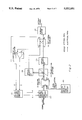
- FIG. 1 shows a circuit structure of a prior art heterodyne detecting receiving apparatus used to achieve this positive control.
- the signal light transmitted through an optical fiber is inputted to mixing circuit 2 through polarization apparatus 1 and is then mixed with local oscillation light outputted from optical local oscillating circuit 3.
- the local oscillating light is assumed to be in a polarized state in which the principal axis angle is slanted, for example, by 45 degrees and the elliptic ratio is 1.
- One output signal from mixing circuit 2 is subjected to heterodyne detection by optical receiver 4 and is converted to an intermediate frequency signal. This intermediate frequency signal is demodulated by demodulator 5 and outputted therefrom.
- the other output signal from mixing circuit 2 is used to monitor the polarization state of the signal light.
- the optical signal for monitoring is first divided into two portions by half mirror 6 and the transparent light is separated by polarization splitter 7 into two polarization components which intersect at right angles.
- the optical signal is thereafter converted into an electrical signal by optical receivers 8 and 9.
- the light reflected from half mirror 6 is subjected to a conversion of its polarization state by ⁇ /4 plate 10 (for example, a linearly polarized light is converted to a circularly polarized light or a circularly polarized light is converted into a linearly polarized light) and subsequently the reflected light is separated into two orthogonal polarization components by polarization splitter 11, whose axis is rotated 45 degrees from that of polarization splitter 7 and is thereafter converted into an electrical signal by optical receivers 12 and 13.
- the output signals from optical receivers 8 and 9 are inputted to differential amplifier 14 and the output signals from optical receivers 12 and 13 are inputted to the other differential amplifier 15.
- Differential amplifier signals A and B obtained from differential amplifiers 14 and 15 are used as monitor signals by polarization operation apparatus 1 to control the polarization state of the signal light.
- the principal axis angle of the polarization state of the signal light is controlled by making signal A equal to 0 and the elliptic ratio is controlled by making signal B equal to 0.
- a part of the signal light is divided into two portions by half mirror 6 and polarization splitters 7 and 11, and the polarization state of the signal light is monitored by four optical receivers 8, 9, 12 and 13, thus controlling the polarization state of the signal light.
- the structure of the optical system becomes complicated as half mirror 6, ⁇ /4 plate 10, the two polarization splitters 7 and 11, and the four optical receivers 8, 9, 12 and 13 must be used for merely monitoring the polarization state of signal light, even when optuical receivers are required, resulting in the problem that the apparatus must be large. A part of the signal light is divided and used only for monitoring. Thus, the receiving sensitivity is deteriorated by an amount corresponding to the use of such a monitoring system. Further, there is a problem that the prior art apparatus cannot form a DBOR (Dual Balanced Optical Signal Receiver, refer to Japanese Patent Kokai Nos. 63-19928 and 63-1124, U.S. application Ser. No. 064058/87, EPC Application No. 87108787, Canadian Application No. 539613/87) which makes it possible to perform a high-sensitivity receiving operation by using the signal component effectively supressing the noise component.
- DBOR Dual Balanced Optical Signal Receiver
- An object of the present invention is to provide a simply structured optical system for monitoring the polarization state of a signal light and for receiving the light with high sensitivity.
- a feature of the present invention is to provide a heterodyne receiver for coherent optical communication comprising an optical local oscillating circuit for producing a local oscillation light, a polarization operating apparatus for varying the polarization state of a signal light transmitted through a light transmission path, a mixing circuit for mixing a signal light having its polarization state corrected by said polarization operating apparatus with a local oscillation light outputted from said optical local oscillating circuit, a polarization splitter for separating an output light from said mixing circuit into two kinds of polarization component, optical receivers for detecting signals for every polarization component obtained from said polarization splitter to provide an intermediate frequency signal, a 90-degree hybrid coupler for receiving two intermediate frequency signals outputted from said optical receivers, a demodulator for demodulating an intermediate frequency signal outputted from said 90-degree hybrid coupler, and a polarization control circuit for controlling the polarization state of said signal output, by driving said polarization operating apparatus based on respective output signals from said optical receivers and said 90-degree hybrid
- FIG. 1 is a block diagram showing the heterodyne receiving apparatus of the prior art.
- FIG. 2 is a principle block diagram of the present invention
- FIG. 3 is a block diagram of a first embodiment of the present invention
- FIG. 4 is a block diagram of an example of a structure of a polarization control circuit 29 shown in FIG. 3,
- FIG. 5 is a block diagram of an example of a structure of a polarization operating apparatus 20 shown in FIG. 3,
- FIG. 6 shows an example of processing by numerical value processing circuit 29c, shown in FIG. 4 and
- FIG. 7 is a block diagram of a second embodiment of the present invention.
- FIG. 2 shows a principle block diagram of the present invention.
- a signal light transmitted through a light transmission path is provided to mixing circuit 21 through polarization operating apparatus 20 and a local oscillation light from optical local oscillation circuit 22 is inputted to mixing circuit 21 in which a signal light is mixed with a local oscillation light.
- the polarization state of the local oscillation light is made to have its principle axis angle slanted by, forexample, 45 degrees.
- the mixed light is separated by polarization aplitter 23 into two orthogonal polarization components to each other.
- Thecomponents are subjected to respective heterodyne detections in optical receivers 24 and 25 to provide an intermediate frequency signal.
- the structure explained up to this point comprises an optical system.
- intermediate frequency signals outputted from optical receivers 24 and 25 are provided to 90-degree hybrid coupler 26 and the output signal from output port P4 is demodulated by demodulator27 to form an output.
- intermediate frequency signals outputted from optical receivers 24 and 25 are inputted to a subtracting circuit, for example, to differential amplifier 28; the output signal b from differential amplifier 28 is provided to polarization control circuit29; and the other output port P3 of 90-degree hybrid coupler 26 is added topolarization control circuit 29.
- Polarization control circuit 29 produces control signals A and B based on the above signals a and b to drive a polarization operating apparatus 20 and control the polarization state (i.e. principal axis angle and elliptic ratio) of the signal light.
- two orthogonal polarization components are separated by polarization splitter 23 and detected by respective optical receivers 24 and 25 to be subject to a heterodyne detection. Therefore, the power of two intermediate frequency signals obtained by the heterodyne detection are compared to detect how far the output signal b from differential amplifier 28 is shifted from 0. This enables the degree of the shift of the principal axis of the polarization state of the signal light from the 45-degree angle to be detected. Therefore, by driving polarization operating apparatus 20 by polarization control circuit 29 so that signal b becomes 0, the principal axis of the polarization state of the signal light is maintained at an angle of 45 degrees.
- the emphasized beat component can be obtained from port p4 of 90-degree hybrid coupler 26, and the image component can be outputted fromthe other port p3 to be canceled.
- the image component can be deleted from the intermediate frequency signal outputted from port p4.
- At least two optical receiving apparatuses may be sufficient, thus making the optical system simpler thanthat of the prior art, and enabling a reduction in size of the apparatus asa whole. It is not necessary to divide the signal light only for the purpose of monitoring its polarization state. This can be monitored via the electric signal stage, thereby enabling the light to be received with a higher sensitivity than in the prior art. Further, it is possible to construct the present invention using a DBOR and in this case, a still higher sensitivity reception is possible.
- FIG. 3 shows a block diagram of a first embodiment of the present invention.
- the optical system comprises polarization operating apparatus 20, mixing circuit 21 comprising a photo coupler, light local oscillating circuit 22 comprising a semiconductor lazer, polarization splitter 23, andtwo optical receivers 24 and 25 comprising photo transistors.
- the electrical signal stage comprises 90-degree hybrid coupler 26, demodulator27, differential amplifier 28, polarization control circuit 29 and AFC (automatic frequency controller) 30, and power monitors 41, 42, 43 comprising diodes and so on.
- Polarization control circuit 29 and polarization operating apparatus 20 are shown in FIGS. 3 and 4.
- Polarization control circuit 29, shown in FIGS. 3 and 4 comprises A/D converters 29a and 29b and is for converting input analog signals a and b to digital signals.
- Numerical value processing circuit 29c is for performing numerical processing based on the digital signal, and pulse motor driving circuits 29d and 29e are for outputting control signals A and B for driving pulse motors 20c and 20d (which should be referred to inFIG. 5), based on the result of the above numerical value processing.
- the above numerical process is conducted by using a so called mountain climbing algorithm to control the outputs A and B from pulse motor drivingcircuit 29d and 29e so that the input signals a and b are made 0 or a minimum value. More concretely, as shown in FIG. 6, the output A is increased by a small value ⁇ A. If signal a increases, the output A is decreased by ⁇ A to return the output A to the original value. On the other hand, if signal a does not increase, the case is considered as correct (OK). By repeating this process, output A is set when signal a becomes 0 (or a minimum value). Actually such a process can be simultaneously conducted with output B and signal b.
- Outputs A and B are set to the optimum when, the signals a and b become 0 or a minimum value simultaneously.
- Analog signals a and b need not be subjected to A/D conversion, but may be subjected to numerical processing at numerical value processing circuit 29c.
- polarization operation apparatus 20 comprises ⁇ /4 plate 20a and ⁇ /2 plate 20b disposed in seriesaround the optical path of the signal light and pulse motor 20c and 20d forperforming rotation control in accordance with signals A and B.
- ⁇ /4 plate 20a is changed by pulse motor 20c
- the elliptic ratio of the signal light can be changed.
- the rotation angle of ⁇ /2 plate 20d is changed by pulse motor 20d
- the principalaxis angle of the signal light can be changed.
- the signal light transmitted along the optical fiber is inputted to one of the input ports p1 of mixing circuit 21 through polarization operating apparatus 20.
- Optical local oscillating circuit 22 produces an optical oscillating light which is inputted to the other port p2 of mixing circuit 21.
- the signal light and local oscillatinglight are mixed in mixing circuit 21, thereby producing a light signal having the beat component from output port p3.
- the light signal is dividedby polarization splitter 23 into two polarization components, in the X and Y directions, which are interposed with each other.
- the light signal is thereafter subjected to heterodyne detection by optical receiving apparatuses 24 and 25.
- the local oscillation light is formed in a polarization state having a principal axis at a 45-degree slant (for example, in the state of circularpolarization, or 45-degree or 135-degree linear polarization), and the light powers of the polarizabtion components in the X and Y directions aremade equal by polarization splitter 23.
- the polarization state of the localoscillation light is expressed in the following equations. ##EQU1##
- ⁇ LO 45-degree linear polarization light or circular polarization light.
- the signal light has a principal angle of 45 degrees and a phase difference of 90 degrees from the polarization state of the local oscillation light.
- the polarization state of the signal light designates circular polarization light
- the polarization state of the signal light is made to show 45-degree or 135-degree linear polarization.
- the polarization state of the signal light is made to represent circular polarization light.
- the local oscillation lights are mixed in mixing circuit 21 and thereafter the signal light is divided by polarization splitter 23 into two orthogonal polarization components and is subjected to a heterodyne detection by optical receivers 24 and 25. Therefore, the intermediate frequency signals I X and I Y which are shifted from each other by 90 degrees in phase can be obtained from ##EQU3## The process in the electrical signal stage will be explained in detail hereinafter.
- Two intermediate frequency signals I X and I Y are respectively inputted to input ports P1 and P2 of 90-degree hybrid coupler 26 and have their phases delayed by 90 degrees, and the outputs corresponding to the intermediate frequency signals are outputted from output ports P3 and P4 of 90-degree hybrid coupler 26.
- the phase does not change along the path from port P1 to port P3 and the path from port P2 to port P4, but is delayed by 90 degrees along the path from port P1 to port P4 and the path from port P2 to port P3.
- the outputs O X and O Y from 90-degree hybrid coupler 26 are expressed by ##EQU4##where [ ]means the phase delay by 90 degrees. It is also defined that ##EQU5##
- Two orthogonal polarization components comprising, for example, 0-degree polarization components and a 90-degree polarization component, which are separated by polarization aplitter 23, are subjected to heterodyne detection by optical receivers 24 and 25. Therefore, the powers of two intermediate frequency signals I X and I Y obtained by heterodyne detection are compared and it can thus be detected how far the principal axis angle in the polarization state of the signal light is shifted from 45-degrees.
- the envelope of the intermediate frequency signals I X and I Y are detected by power monitors 42, 43 and only the power is read out to input to differential amplifier 28 and the output thereof is applied to polarization control circuit 29 as signal b.
- the amount by which signal b is shifted from 0 corresponds to the amount by which the principal axis angle in the polarization state of the signal light is shifted from 45 degrees. Therefore, by driving polarization operating apparatus 20 by polarization control circuit 29 so that signal b becomes 0, the principal axis angle inthe polarization state of the signal light is maintained at 45 degrees.
- Thepolarization state of the signal light is made a circular (where the local oscillation light is in 45-degree or 135-degree linear polarization), or is made 45-degree or 135-degree (where the local oscillation light is in circular polarization).
- the amplified beat components are obtained from ports P4 of 90-degree hybrid coupler 26 and the image components are outputted from port P3 to cancel each other out.
- the image component can be deleted from the intermediate frequency signal outputted from port P4 by driving polarization operating apparatus 20 by polarization control circuit 29 so that signal a is made 0 as described above.
- the present embodiment employs only two optical receiving apparatuses and its structure is made simpler than that of the prior art optical system, thereby realizing a miniaturization of the apparatus as a whole.
- the signal light is not divided merely for the purpose of monitoring the polarization state of the signal light.
- the polarization state can be monitored in the electrical signal stage, thereby making the receiving sensitivity much better than in the prior art.
- FIG. 7 shows a block diagram of the second embodiment of the present invention.
- This embodiment is formed of a DBOR (Dual Balanced Optical Reciver). Namely, another pair comprising polarization splitter 31 and optical receivers 32 and 33, having a structure similar to the aforementioned polarization splitter 23 and optical receivers 24 and 25, is provided to port P4 of mixing circuit 21 in the first embodiment. The output from optical receivers 24 and 32 are applied to subtractor 35.
- DBOR Double Balanced Optical Reciver
- the signal light is mixed with the local oscillation light in mixing circuit 21, and optical signals having a phase difference of 180 degrees are outputted from ports P3 and P4.
- These light signals are divided into equal parts by polarization splitters 23 and 31 and then subjected to heterodyne detection by light receivers 24, 25, 32 and 33.
- the intermediate frequency signal obtained by optical receivers 24 and 32 are applied to subtractor 34 and the intermediate signals obtained by optical receivers 25 and 33 are applied to subtractor 35.
- beat components having a 180-degree phase difference areinputted to optical receivers 24 and 32 and similarly beat components having a 180-degree phase difference are inputted to optical receivers 25 and 33.
- the beat components are added to be amplified and noise intensity components of the local oscillation light cancel each other in subtractors34 and 35.
- the intermediate frequency signal in which the noise intensity component is suppressed is inputted to 90-degree hybrid coupler 26 and differential amplifier 28. Thereafter, the same process as in the first embodiment is continued.
- the second embodiment effectively utilizes two output lights from mixing circuit 21, thereby suppressing the excess intensity noise of the local oscillation light and greatly increasing the receiving sensitivity.
- the above embodiments describe the case where either the signal light or the local oscillation light is made to be in 45-degree (or 135-degree) linear polarization and the other is made to be in circular polarization. It is not always necessary to use the above arrangement. Namely, it is a required condition that both the signal light and local oscillation light be in a polarization state having their principal axes at 45 degrees, and that the phase difference between them be 90 degrees. Any polarization state satisfying the above condition may be used.
- the signal light may have elliptic polarization with 110-degree phase difference between the X components and Y components of the signal light
- the local oscillation light may have elliptic polarization with a phase difference of 20 degrees between the X and Y components of the local oscillation light.
- the circuit for inverting the signals from the power monitor 42 and the circuit for outputting the signal b by adding the output of the inverting circuit to the output from the power monitor 43 may be employed.
- polarization operating apparatus 20 instead of the structure shown in FIG. 5, a wave guide device comprising an electrical optical crystal such as lithium niobate may be employed to perform a phase modulation by applying an appropriate voltage to the electrodes provided on the wave guide device, thereby enabling the polarization state of the signal light to be changed.
- a wave guide device comprising an electrical optical crystal such as lithium niobate may be employed to perform a phase modulation by applying an appropriate voltage to the electrodes provided on the wave guide device, thereby enabling the polarization state of the signal light to be changed.
- At least two optical receivers may be sufficient and thus, the structure of the optical system may be simplifiedand the apparatus as a whole may be miniaturized.
- the signal light is not divided merely for monitoring its polarization state and the polarization state may be monitored in the electrical signal stage. Therefore, a much higher sensitivity can be achieved upon receiving the signal light than inthe prior art.
- the present invention may be easily formed using a DBOR, even higher sensitivity reception is possible.
- the image component may be deleted from the other output signal.
Landscapes
- Physics & Mathematics (AREA)
- Electromagnetism (AREA)
- Engineering & Computer Science (AREA)
- Computer Networks & Wireless Communication (AREA)
- Signal Processing (AREA)
- Optical Communication System (AREA)
Applications Claiming Priority (2)
| Application Number | Priority Date | Filing Date | Title |
|---|---|---|---|
| JP63262943A JPH0734080B2 (ja) | 1988-10-20 | 1988-10-20 | コヒーレント光通信用ヘテロダイン検波受信装置 |
| JP63-262943 | 1988-10-20 |
Publications (1)
| Publication Number | Publication Date |
|---|---|
| US5052051A true US5052051A (en) | 1991-09-24 |
Family
ID=17382721
Family Applications (1)
| Application Number | Title | Priority Date | Filing Date |
|---|---|---|---|
| US07/424,732 Expired - Fee Related US5052051A (en) | 1988-10-20 | 1989-10-20 | Heterodyne receiver for coherent optical communication |
Country Status (4)
| Country | Link |
|---|---|
| US (1) | US5052051A (fr) |
| EP (1) | EP0365028B1 (fr) |
| JP (1) | JPH0734080B2 (fr) |
| CA (1) | CA2000997C (fr) |
Cited By (28)
| Publication number | Priority date | Publication date | Assignee | Title |
|---|---|---|---|---|
| US5258615A (en) * | 1990-08-03 | 1993-11-02 | Gpt Limited | Optical fiber monitoring by detection of polarization variations |
| US5293264A (en) * | 1990-12-10 | 1994-03-08 | Koninklijke Ptt Nederland N.V. | Transmission system for the polarization-insensitive transmission of signals |
| US5295013A (en) * | 1992-03-23 | 1994-03-15 | Nec Corporation | Optical receiver of direct detection type |
| US5367397A (en) * | 1990-10-15 | 1994-11-22 | Nec Corporation | Wavelength-stabilizing method and its associated circuitry for an optical communication system |
| US5414550A (en) * | 1992-04-27 | 1995-05-09 | Nec Corporation | Optical heterodyne detector and receiver |
| US5432632A (en) * | 1991-09-13 | 1995-07-11 | Fujitsu Limited | Optical communication system |
| US5574589A (en) * | 1995-01-09 | 1996-11-12 | Lucent Technologies Inc. | Self-amplified networks |
| US5574553A (en) * | 1994-12-27 | 1996-11-12 | The United States Of America As Represented By The Secretary Of The Air Force | Ladar receiver incorporating an optical amplifier and polarization optical mixer |
| US5596441A (en) * | 1994-04-13 | 1997-01-21 | Ando Electric Co., Ltd. | Optical polarization controller |
| WO2000077956A1 (fr) * | 1999-06-10 | 2000-12-21 | Fiberspace, Inc. | Procede et appareil d'utilisation de techniques de melange d'hyperfrequences/rf pour selectionner une bande donnee d'une transmission optique |
| US20010028679A1 (en) * | 2000-03-17 | 2001-10-11 | Chien Chou | Phase demodulator, phase difference detector, and interferometric system using the phase difference detector |
| US6459826B1 (en) * | 2000-03-21 | 2002-10-01 | Lucent Technologies Inc. | Programmable optical switch apparatus |
| US20040037560A1 (en) * | 1999-06-10 | 2004-02-26 | Mells Bradley M. | Method and apparatus of utilizing RF/microwave and optical mixing techniques to select a given band of an optical transmission |
| US20050232644A1 (en) * | 2004-04-20 | 2005-10-20 | Moeller Lothar Benedict E J | Optical heterodyne receiver based on oversampling |
| US20060171718A1 (en) * | 2005-01-31 | 2006-08-03 | Fujitsu Limited | Optical receiver and optical reception method compatible with differential quadrature phase shift keying |
| US20070036557A1 (en) * | 2005-06-09 | 2007-02-15 | Jackson John E | Wide field of view heterodyne receiver |
| US20070177885A1 (en) * | 2004-04-15 | 2007-08-02 | Abe Jun Ichi | Optical receiver |
| US20070297806A1 (en) * | 2006-06-23 | 2007-12-27 | Lucent Technologies, Incorporated | System and method for receiving coherent, polarizaztion-multiplexed optical signals |
| US20080038001A1 (en) * | 2006-03-10 | 2008-02-14 | Becker Donald A | Feedback-controlled coherent optical receiver with electrical compensation/equalization |
| US20090080887A1 (en) * | 2007-09-25 | 2009-03-26 | Levinson Frank H | Parallel Transmission of Data Streams in a Star-Configured Network |
| US20130058653A1 (en) * | 2010-05-19 | 2013-03-07 | Nokia Siemens Networks Oy | Optical network unit, method for processing data in an optical network and communication system |
| CN104221309A (zh) * | 2012-03-30 | 2014-12-17 | 住友大阪水泥股份有限公司 | 光90度混合电路及使用该光90度混合电路的光接收器 |
| US20150256266A1 (en) * | 2014-03-10 | 2015-09-10 | Cisco Technology, Inc. | Common Mode Rejection Ratio Control for Coherent Optical Receivers |
| CN110945803A (zh) * | 2017-07-25 | 2020-03-31 | 凯迪迪爱通信技术有限公司 | 光接收机和相干光接收方法 |
| US10833767B2 (en) * | 2018-01-24 | 2020-11-10 | Indian Institute Of Technology Bombay | Self-homodyne carrier multiplexed transmission system and method for coherent optical links |
| CN112640329A (zh) * | 2018-09-07 | 2021-04-09 | 日本电气株式会社 | 光学接收器和接收方法 |
| EP3886342A1 (fr) * | 2020-03-24 | 2021-09-29 | Mitsubishi Electric R & D Centre Europe B.V. | Récepteur optique cohérent |
| US11569916B2 (en) * | 2018-08-27 | 2023-01-31 | Zte Corporation | Coherent detection implementing apparatus, system and method |
Families Citing this family (4)
| Publication number | Priority date | Publication date | Assignee | Title |
|---|---|---|---|---|
| EP0844748B1 (fr) * | 1996-11-25 | 1999-06-16 | Oerlikon Contraves AG | Procédé et appareil de transmission optique de données sur un trajet en espace libre |
| EP1014604B1 (fr) | 1998-12-22 | 2005-06-22 | Contraves Space Ag | Procédé et appareil pour la production d'un signal d'erreur en cas de réception hétérodyne cohérente des ondes lumineuses |
| JP2006013573A (ja) * | 2004-06-22 | 2006-01-12 | Hitachi Ltd | 量子光伝送装置 |
| WO2013042345A1 (fr) * | 2011-09-22 | 2013-03-28 | 日本電気株式会社 | Dispositif de traitement de signal optique, dispositif de traitement de polarisation et procédé de traitement de signal optique |
Citations (2)
| Publication number | Priority date | Publication date | Assignee | Title |
|---|---|---|---|---|
| EP0310174A1 (fr) * | 1987-09-28 | 1989-04-05 | Koninklijke Philips Electronics N.V. | Dispositif pour la détection optique hétérodyne ou synchrone d'un faisceau de signal optique et récepteur muni d'un pareil dispositif |
| US4856093A (en) * | 1986-06-28 | 1989-08-08 | Alcatel N.V. | Optical heterodyne receiver |
Family Cites Families (3)
| Publication number | Priority date | Publication date | Assignee | Title |
|---|---|---|---|---|
| JPS6123121A (ja) * | 1984-07-12 | 1986-01-31 | Nec Corp | 光ヘテロダイン受信方法 |
| GB8514264D0 (en) * | 1985-06-06 | 1985-07-10 | British Telecomm | Coherent optical receivers |
| US4723317A (en) * | 1986-05-08 | 1988-02-02 | American Telephone And Telegraph Company, At&T Bell Laboratories | Optical heterodyne mixers providing image-frequency rejection |
-
1988
- 1988-10-20 JP JP63262943A patent/JPH0734080B2/ja not_active Expired - Lifetime
-
1989
- 1989-10-19 CA CA002000997A patent/CA2000997C/fr not_active Expired - Fee Related
- 1989-10-20 EP EP89119515A patent/EP0365028B1/fr not_active Expired - Lifetime
- 1989-10-20 US US07/424,732 patent/US5052051A/en not_active Expired - Fee Related
Patent Citations (2)
| Publication number | Priority date | Publication date | Assignee | Title |
|---|---|---|---|---|
| US4856093A (en) * | 1986-06-28 | 1989-08-08 | Alcatel N.V. | Optical heterodyne receiver |
| EP0310174A1 (fr) * | 1987-09-28 | 1989-04-05 | Koninklijke Philips Electronics N.V. | Dispositif pour la détection optique hétérodyne ou synchrone d'un faisceau de signal optique et récepteur muni d'un pareil dispositif |
Non-Patent Citations (6)
| Title |
|---|
| Imai et al., "Optical Polarization Control Utilising an Optical Heterodyne Detection Scheme", Electronic Letters, 1-21-85, vol. 21, #2, pp. 52-53. |
| Imai et al., Optical Polarization Control Utilising an Optical Heterodyne Detection Scheme , Electronic Letters, 1 21 85, vol. 21, 2, pp. 52 53. * |
| Kidoh, "Polarization Control on Output of Single Mode Fiber", IEEE Journal on Quantum Electronics, vol. QE17 #6, 6-81. |
| Kidoh, Polarization Control on Output of Single Mode Fiber , IEEE Journal on Quantum Electronics, vol. QE17 6, 6 81. * |
| Naito et al., "Wideband Optical Image Rejection Receiver and Its Crosstalk Penalty", Electronics Letters, Jul. 6, 1989, vol. 25, No. 14, pp. 895-896. |
| Naito et al., Wideband Optical Image Rejection Receiver and Its Crosstalk Penalty , Electronics Letters, Jul. 6, 1989, vol. 25, No. 14, pp. 895 896. * |
Cited By (49)
| Publication number | Priority date | Publication date | Assignee | Title |
|---|---|---|---|---|
| US5258615A (en) * | 1990-08-03 | 1993-11-02 | Gpt Limited | Optical fiber monitoring by detection of polarization variations |
| US5367397A (en) * | 1990-10-15 | 1994-11-22 | Nec Corporation | Wavelength-stabilizing method and its associated circuitry for an optical communication system |
| US5293264A (en) * | 1990-12-10 | 1994-03-08 | Koninklijke Ptt Nederland N.V. | Transmission system for the polarization-insensitive transmission of signals |
| US5432632A (en) * | 1991-09-13 | 1995-07-11 | Fujitsu Limited | Optical communication system |
| US5295013A (en) * | 1992-03-23 | 1994-03-15 | Nec Corporation | Optical receiver of direct detection type |
| US5414550A (en) * | 1992-04-27 | 1995-05-09 | Nec Corporation | Optical heterodyne detector and receiver |
| US5596441A (en) * | 1994-04-13 | 1997-01-21 | Ando Electric Co., Ltd. | Optical polarization controller |
| US5574553A (en) * | 1994-12-27 | 1996-11-12 | The United States Of America As Represented By The Secretary Of The Air Force | Ladar receiver incorporating an optical amplifier and polarization optical mixer |
| US5574589A (en) * | 1995-01-09 | 1996-11-12 | Lucent Technologies Inc. | Self-amplified networks |
| WO2000077956A1 (fr) * | 1999-06-10 | 2000-12-21 | Fiberspace, Inc. | Procede et appareil d'utilisation de techniques de melange d'hyperfrequences/rf pour selectionner une bande donnee d'une transmission optique |
| US20040037560A1 (en) * | 1999-06-10 | 2004-02-26 | Mells Bradley M. | Method and apparatus of utilizing RF/microwave and optical mixing techniques to select a given band of an optical transmission |
| US20010028679A1 (en) * | 2000-03-17 | 2001-10-11 | Chien Chou | Phase demodulator, phase difference detector, and interferometric system using the phase difference detector |
| US7006562B2 (en) * | 2000-03-17 | 2006-02-28 | Chien Chou | Phase demodulator, phase difference detector, and interferometric system using the phase difference detector |
| US6459826B1 (en) * | 2000-03-21 | 2002-10-01 | Lucent Technologies Inc. | Programmable optical switch apparatus |
| US6850710B1 (en) | 2000-06-09 | 2005-02-01 | Tip Group, Llc | Method and apparatus of utilizing RF/microwave and optical mixing techniques to select a given band of an optical transmission |
| US7903982B2 (en) * | 2004-04-15 | 2011-03-08 | Mitsubishi Electric Corporation | Optical receiver |
| US20070177885A1 (en) * | 2004-04-15 | 2007-08-02 | Abe Jun Ichi | Optical receiver |
| US7330669B2 (en) | 2004-04-20 | 2008-02-12 | Lucent Technologies Inc. | Optical heterodyne receiver based on oversampling |
| US20050232644A1 (en) * | 2004-04-20 | 2005-10-20 | Moeller Lothar Benedict E J | Optical heterodyne receiver based on oversampling |
| US7529490B2 (en) * | 2005-01-31 | 2009-05-05 | Fujitsu Limited | Optical receiver and optical reception method compatible with differential quadrature phase shift keying |
| US20100189437A1 (en) * | 2005-01-31 | 2010-07-29 | Fujitsu Limited | Optical receiver and optical reception method compatible with differential quadrature phase shift keying |
| US20060171718A1 (en) * | 2005-01-31 | 2006-08-03 | Fujitsu Limited | Optical receiver and optical reception method compatible with differential quadrature phase shift keying |
| US7860394B2 (en) | 2005-01-31 | 2010-12-28 | Fujitsu Limited | Optical receiver and optical reception method compatible with differential quadrature phase shift keying |
| US20070036557A1 (en) * | 2005-06-09 | 2007-02-15 | Jackson John E | Wide field of view heterodyne receiver |
| US7561813B2 (en) * | 2005-06-09 | 2009-07-14 | Northrop Grumman Corporation | Wide field of view heterodyne receiver |
| US20080038001A1 (en) * | 2006-03-10 | 2008-02-14 | Becker Donald A | Feedback-controlled coherent optical receiver with electrical compensation/equalization |
| US7406269B2 (en) | 2006-03-10 | 2008-07-29 | Discovery Semiconductors, Inc. | Feedback-controlled coherent optical receiver with electrical compensation/equalization |
| US20070297806A1 (en) * | 2006-06-23 | 2007-12-27 | Lucent Technologies, Incorporated | System and method for receiving coherent, polarizaztion-multiplexed optical signals |
| US7809284B2 (en) * | 2006-06-23 | 2010-10-05 | Alcatel-Lucent Usa Inc. | System and method for receiving coherent, polarization-multiplexed optical signals |
| US8233798B2 (en) | 2007-09-25 | 2012-07-31 | Levinson Frank H | Parallel transmission of data streams in a star-configured network |
| US20090080887A1 (en) * | 2007-09-25 | 2009-03-26 | Levinson Frank H | Parallel Transmission of Data Streams in a Star-Configured Network |
| US20130058653A1 (en) * | 2010-05-19 | 2013-03-07 | Nokia Siemens Networks Oy | Optical network unit, method for processing data in an optical network and communication system |
| US9432141B2 (en) * | 2010-05-19 | 2016-08-30 | Xieon Networks S.A.R.L. | Optical network unit, method for processing data in an optical network and communication system |
| CN104221309B (zh) * | 2012-03-30 | 2017-03-29 | 住友大阪水泥股份有限公司 | 光接收器 |
| CN104221309A (zh) * | 2012-03-30 | 2014-12-17 | 住友大阪水泥股份有限公司 | 光90度混合电路及使用该光90度混合电路的光接收器 |
| US20150063810A1 (en) * | 2012-03-30 | 2015-03-05 | Sumitomo Osaka Cement Co., Ltd. | Optical 90-degree hybrid circuit and optical receiver using same |
| US9800349B2 (en) * | 2012-03-30 | 2017-10-24 | Sumitomo Osaka Cement Co., Ltd. | Optical 90-degree hybrid circuit and optical receiver using same |
| US20150256266A1 (en) * | 2014-03-10 | 2015-09-10 | Cisco Technology, Inc. | Common Mode Rejection Ratio Control for Coherent Optical Receivers |
| US9716555B2 (en) | 2014-03-10 | 2017-07-25 | Cisco Technology, Inc. | Common mode rejection ratio control for coherent optical receivers |
| US9337937B2 (en) * | 2014-03-10 | 2016-05-10 | Cisco Technology, Inc. | Common mode rejection ratio control for coherent optical receivers |
| CN110945803A (zh) * | 2017-07-25 | 2020-03-31 | 凯迪迪爱通信技术有限公司 | 光接收机和相干光接收方法 |
| CN110945803B (zh) * | 2017-07-25 | 2022-04-19 | 凯迪迪爱通信技术有限公司 | 光接收机和相干光接收方法 |
| US10833767B2 (en) * | 2018-01-24 | 2020-11-10 | Indian Institute Of Technology Bombay | Self-homodyne carrier multiplexed transmission system and method for coherent optical links |
| US11569916B2 (en) * | 2018-08-27 | 2023-01-31 | Zte Corporation | Coherent detection implementing apparatus, system and method |
| CN112640329A (zh) * | 2018-09-07 | 2021-04-09 | 日本电气株式会社 | 光学接收器和接收方法 |
| US11621783B2 (en) * | 2018-09-07 | 2023-04-04 | Nec Corporation | Optical receiver and receiving method |
| CN112640329B (zh) * | 2018-09-07 | 2025-01-03 | 日本电气株式会社 | 光学接收器和接收方法 |
| EP3886342A1 (fr) * | 2020-03-24 | 2021-09-29 | Mitsubishi Electric R & D Centre Europe B.V. | Récepteur optique cohérent |
| WO2021192451A1 (fr) * | 2020-03-24 | 2021-09-30 | Mitsubishi Electric Corporation | Récepteur optique cohérent et unité de réseau optique |
Also Published As
| Publication number | Publication date |
|---|---|
| JPH0734080B2 (ja) | 1995-04-12 |
| CA2000997C (fr) | 1994-02-08 |
| EP0365028B1 (fr) | 1996-01-24 |
| JPH02110524A (ja) | 1990-04-23 |
| CA2000997A1 (fr) | 1990-04-20 |
| EP0365028A3 (fr) | 1991-12-27 |
| EP0365028A2 (fr) | 1990-04-25 |
Similar Documents
| Publication | Publication Date | Title |
|---|---|---|
| US5052051A (en) | Heterodyne receiver for coherent optical communication | |
| US4817206A (en) | Optical-fiber transmission system with polarization modulation and heterodyne coherent detection | |
| EP0352747B1 (fr) | Procédé de stabilisation d'une séparation de fréquence pour communication optique hétérodyne ou homodyne | |
| EP0409260B1 (fr) | Récepteur pour communication optique cohérente | |
| JPH0828682B2 (ja) | 光ハイブリッド装置と偏光独立コヒーレント光波検出装置 | |
| EP0467358B1 (fr) | Démodulateur et récepteur à diversité de polarisation pour communication optique cohérente comprenant le démodulateur | |
| US5272555A (en) | Bidirectional optical transmission method and apparatus therefor | |
| EP0245026B1 (fr) | Mélangeur optique hétérodyne procurant une réjection des fréquences-images | |
| EP0456365A2 (fr) | Hybride optique pour des systèmes de détection cohérents | |
| CA1308440C (fr) | Methode de communication optique a diversite de polarisation et appareil utilisant cette methode | |
| JP3443810B2 (ja) | 偏光制御回路 | |
| US12526053B2 (en) | Optical transmission device and system | |
| JPS6123121A (ja) | 光ヘテロダイン受信方法 | |
| JPS63224427A (ja) | 偏波ダイバシテイ光受信方法及びその装置 | |
| JP2668410B2 (ja) | イメージリジェクションミキサ | |
| JPS61189516A (ja) | 光偏波軸固定装置 | |
| JPH05303128A (ja) | イメージ信号除去光ヘテロダイン検波受信装置 | |
| JPS6221128A (ja) | 光ヘテロダイン検波装置 | |
| JPH05127125A (ja) | コヒーレント光波通信用光受信機 | |
| JPH0671232B2 (ja) | 二重平衡偏波ダイバ−シティ受信装置 | |
| JPH03259632A (ja) | 光ヘテロダイン偏波ダイバーシティ受信器 | |
| JPH03116120A (ja) | 光受信回路 | |
| JPH03257431A (ja) | コヒーレント光通信方法及びコヒーレント光通信システム | |
| JPH0226146A (ja) | 光ヘテロダイン検波回路 | |
| JPH05257185A (ja) | 光受信装置 |
Legal Events
| Date | Code | Title | Description |
|---|---|---|---|
| AS | Assignment |
Owner name: FUJITSU LIMITED, 1015, KAMIKODANAKA, NAKAHARA-KU, Free format text: ASSIGNMENT OF ASSIGNORS INTEREST.;ASSIGNORS:NAITO, TAKAO;CHIKAMA, TERUMI;WATANABE, SHIGEKI;AND OTHERS;REEL/FRAME:005162/0750 Effective date: 19891009 |
|
| CC | Certificate of correction | ||
| FEPP | Fee payment procedure |
Free format text: PAYOR NUMBER ASSIGNED (ORIGINAL EVENT CODE: ASPN); ENTITY STATUS OF PATENT OWNER: LARGE ENTITY |
|
| FPAY | Fee payment |
Year of fee payment: 4 |
|
| FPAY | Fee payment |
Year of fee payment: 8 |
|
| REMI | Maintenance fee reminder mailed | ||
| LAPS | Lapse for failure to pay maintenance fees | ||
| STCH | Information on status: patent discontinuation |
Free format text: PATENT EXPIRED DUE TO NONPAYMENT OF MAINTENANCE FEES UNDER 37 CFR 1.362 |
|
| FP | Lapsed due to failure to pay maintenance fee |
Effective date: 20030924 |