US5050992A - Dispersive holographic spectrometer - Google Patents
Dispersive holographic spectrometer Download PDFInfo
- Publication number
- US5050992A US5050992A US07/508,436 US50843690A US5050992A US 5050992 A US5050992 A US 5050992A US 50843690 A US50843690 A US 50843690A US 5050992 A US5050992 A US 5050992A
- Authority
- US
- United States
- Prior art keywords
- radiation
- detector
- holographic
- spectrometer
- piezoelectric block
- Prior art date
- Legal status (The legal status is an assumption and is not a legal conclusion. Google has not performed a legal analysis and makes no representation as to the accuracy of the status listed.)
- Expired - Lifetime
Links
- 230000005855 radiation Effects 0.000 claims abstract description 85
- 230000005684 electric field Effects 0.000 claims abstract description 5
- 238000000034 method Methods 0.000 claims description 12
- 238000001228 spectrum Methods 0.000 claims description 11
- 238000010183 spectrum analysis Methods 0.000 claims description 7
- GQYHUHYESMUTHG-UHFFFAOYSA-N lithium niobate Chemical group [Li+].[O-][Nb](=O)=O GQYHUHYESMUTHG-UHFFFAOYSA-N 0.000 claims description 4
- 239000000463 material Substances 0.000 claims description 3
- 239000006185 dispersion Substances 0.000 claims description 2
- 238000000862 absorption spectrum Methods 0.000 abstract description 7
- 239000007789 gas Substances 0.000 description 12
- 239000000523 sample Substances 0.000 description 9
- 230000003595 spectral effect Effects 0.000 description 8
- 230000008901 benefit Effects 0.000 description 5
- 238000010521 absorption reaction Methods 0.000 description 4
- 230000000694 effects Effects 0.000 description 3
- 230000005670 electromagnetic radiation Effects 0.000 description 3
- 230000008030 elimination Effects 0.000 description 3
- 238000003379 elimination reaction Methods 0.000 description 3
- 238000004611 spectroscopical analysis Methods 0.000 description 3
- 239000000853 adhesive Substances 0.000 description 2
- 230000001070 adhesive effect Effects 0.000 description 2
- 239000000470 constituent Substances 0.000 description 2
- 239000013078 crystal Substances 0.000 description 2
- 229910052709 silver Inorganic materials 0.000 description 2
- 239000004332 silver Substances 0.000 description 2
- -1 silver halide Chemical class 0.000 description 2
- 239000000758 substrate Substances 0.000 description 2
- 230000004075 alteration Effects 0.000 description 1
- 238000004458 analytical method Methods 0.000 description 1
- 239000004568 cement Substances 0.000 description 1
- 230000006835 compression Effects 0.000 description 1
- 238000007906 compression Methods 0.000 description 1
- 239000000839 emulsion Substances 0.000 description 1
- 238000001413 far-infrared spectroscopy Methods 0.000 description 1
- 239000011521 glass Substances 0.000 description 1
- 238000002329 infrared spectrum Methods 0.000 description 1
- 230000002452 interceptive effect Effects 0.000 description 1
- 230000001678 irradiating effect Effects 0.000 description 1
- 230000007246 mechanism Effects 0.000 description 1
- 238000012986 modification Methods 0.000 description 1
- 230000004048 modification Effects 0.000 description 1
- 230000003287 optical effect Effects 0.000 description 1
- 239000002245 particle Substances 0.000 description 1
- 230000008569 process Effects 0.000 description 1
- 239000013074 reference sample Substances 0.000 description 1
- 238000007789 sealing Methods 0.000 description 1
- 230000035945 sensitivity Effects 0.000 description 1
- 239000012780 transparent material Substances 0.000 description 1
Images

Classifications
-
- G—PHYSICS
- G01—MEASURING; TESTING
- G01J—MEASUREMENT OF INTENSITY, VELOCITY, SPECTRAL CONTENT, POLARISATION, PHASE OR PULSE CHARACTERISTICS OF INFRARED, VISIBLE OR ULTRAVIOLET LIGHT; COLORIMETRY; RADIATION PYROMETRY
- G01J3/00—Spectrometry; Spectrophotometry; Monochromators; Measuring colours
- G01J3/12—Generating the spectrum; Monochromators
- G01J3/18—Generating the spectrum; Monochromators using diffraction elements, e.g. grating
- G01J3/1838—Holographic gratings
-
- G—PHYSICS
- G01—MEASURING; TESTING
- G01J—MEASUREMENT OF INTENSITY, VELOCITY, SPECTRAL CONTENT, POLARISATION, PHASE OR PULSE CHARACTERISTICS OF INFRARED, VISIBLE OR ULTRAVIOLET LIGHT; COLORIMETRY; RADIATION PYROMETRY
- G01J3/00—Spectrometry; Spectrophotometry; Monochromators; Measuring colours
-
- G—PHYSICS
- G01—MEASURING; TESTING
- G01J—MEASUREMENT OF INTENSITY, VELOCITY, SPECTRAL CONTENT, POLARISATION, PHASE OR PULSE CHARACTERISTICS OF INFRARED, VISIBLE OR ULTRAVIOLET LIGHT; COLORIMETRY; RADIATION PYROMETRY
- G01J3/00—Spectrometry; Spectrophotometry; Monochromators; Measuring colours
- G01J3/02—Details
- G01J3/0256—Compact construction
- G01J3/0259—Monolithic
-
- G—PHYSICS
- G01—MEASURING; TESTING
- G01J—MEASUREMENT OF INTENSITY, VELOCITY, SPECTRAL CONTENT, POLARISATION, PHASE OR PULSE CHARACTERISTICS OF INFRARED, VISIBLE OR ULTRAVIOLET LIGHT; COLORIMETRY; RADIATION PYROMETRY
- G01J3/00—Spectrometry; Spectrophotometry; Monochromators; Measuring colours
- G01J3/02—Details
- G01J3/0205—Optical elements not provided otherwise, e.g. optical manifolds, diffusers, windows
- G01J3/0237—Adjustable, e.g. focussing
-
- G—PHYSICS
- G01—MEASURING; TESTING
- G01J—MEASUREMENT OF INTENSITY, VELOCITY, SPECTRAL CONTENT, POLARISATION, PHASE OR PULSE CHARACTERISTICS OF INFRARED, VISIBLE OR ULTRAVIOLET LIGHT; COLORIMETRY; RADIATION PYROMETRY
- G01J3/00—Spectrometry; Spectrophotometry; Monochromators; Measuring colours
- G01J3/02—Details
- G01J3/0256—Compact construction
-
- G—PHYSICS
- G01—MEASURING; TESTING
- G01J—MEASUREMENT OF INTENSITY, VELOCITY, SPECTRAL CONTENT, POLARISATION, PHASE OR PULSE CHARACTERISTICS OF INFRARED, VISIBLE OR ULTRAVIOLET LIGHT; COLORIMETRY; RADIATION PYROMETRY
- G01J3/00—Spectrometry; Spectrophotometry; Monochromators; Measuring colours
- G01J3/02—Details
- G01J3/0286—Constructional arrangements for compensating for fluctuations caused by temperature, humidity or pressure, or using cooling or temperature stabilization of parts of the device; Controlling the atmosphere inside a spectrometer, e.g. vacuum
-
- G—PHYSICS
- G01—MEASURING; TESTING
- G01J—MEASUREMENT OF INTENSITY, VELOCITY, SPECTRAL CONTENT, POLARISATION, PHASE OR PULSE CHARACTERISTICS OF INFRARED, VISIBLE OR ULTRAVIOLET LIGHT; COLORIMETRY; RADIATION PYROMETRY
- G01J3/00—Spectrometry; Spectrophotometry; Monochromators; Measuring colours
- G01J3/02—Details
- G01J3/0289—Field-of-view determination; Aiming or pointing of a spectrometer; Adjusting alignment; Encoding angular position; Size of measurement area; Position tracking
-
- G—PHYSICS
- G01—MEASURING; TESTING
- G01J—MEASUREMENT OF INTENSITY, VELOCITY, SPECTRAL CONTENT, POLARISATION, PHASE OR PULSE CHARACTERISTICS OF INFRARED, VISIBLE OR ULTRAVIOLET LIGHT; COLORIMETRY; RADIATION PYROMETRY
- G01J3/00—Spectrometry; Spectrophotometry; Monochromators; Measuring colours
- G01J3/28—Investigating the spectrum
- G01J3/2803—Investigating the spectrum using photoelectric array detector
-
- G—PHYSICS
- G01—MEASURING; TESTING
- G01N—INVESTIGATING OR ANALYSING MATERIALS BY DETERMINING THEIR CHEMICAL OR PHYSICAL PROPERTIES
- G01N21/00—Investigating or analysing materials by the use of optical means, i.e. using sub-millimetre waves, infrared, visible or ultraviolet light
- G01N21/17—Systems in which incident light is modified in accordance with the properties of the material investigated
- G01N21/25—Colour; Spectral properties, i.e. comparison of effect of material on the light at two or more different wavelengths or wavelength bands
- G01N21/31—Investigating relative effect of material at wavelengths characteristic of specific elements or molecules, e.g. atomic absorption spectrometry
- G01N21/35—Investigating relative effect of material at wavelengths characteristic of specific elements or molecules, e.g. atomic absorption spectrometry using infrared light
- G01N21/3504—Investigating relative effect of material at wavelengths characteristic of specific elements or molecules, e.g. atomic absorption spectrometry using infrared light for analysing gases, e.g. multi-gas analysis
-
- G—PHYSICS
- G01—MEASURING; TESTING
- G01N—INVESTIGATING OR ANALYSING MATERIALS BY DETERMINING THEIR CHEMICAL OR PHYSICAL PROPERTIES
- G01N2201/00—Features of devices classified in G01N21/00
- G01N2201/06—Illumination; Optics
- G01N2201/067—Electro-optic, magneto-optic, acousto-optic elements
Definitions
- This invention relates generally to the field of spectrometry, and more particularly, to a method and apparatus for dispersive holographic spectrometry.
- atomic particles When atomic particles are excited by electromagnetic radiation of certain frequencies, they may absorb some of the radiation at specific wavelengths and give off the energy in other forms, such as electromagnetic radiation of different wavelengths or rotational or vibrational energy.
- a spectrum of the wavelengths absorbed by the sample can be generated over that range of wavelengths of the infrared spectrum. Since different atoms will absorb different wavelengths of radiation, the infrared absorption spectrum of each atom or molecule is unique.
- the elemental and molecular constituents of a sample can be determined by comparing the absorption spectrum of a sample to the absorption spectrum of a reference sample at the same intensity of radiation.
- Spectral information can be measured by two methods generally referred to as the dispersive method and the interferometric method.
- the interferometric method the electromagnetic radiation is divided into at least two paths and then recombined in an interference pattern.
- the interference pattern is measured to give the spectral information.
- the dispersive method separates the radiation into component wavelengths by means of a grating or a prism. Each set of component wavelengths is then individually measured.
- the above-referenced spectrometer system suffers the drawbacks of requiring a reflector to focus the radiation into a relatively small aperture on the holographic spectrometer itself. This requires high precision adjustment using servomechanisms to direct the radiation from the reflector into the aperture. Such mechanisms are expensive and require a significant amount of time for alignment.
- a spectrometer is provided with a holographic lens for dispersing the radiation from a source into component wavelengths which may be detected and analyzed.
- the holographic spectrometer for analyzing spectral data.
- the holographic spectrometer comprises an insulative piezoelectric crystal in the form of a block, having a relatively large holographic lens at one face, an array of charge coupled detectors (CCD) at another face, and a pair of vernier electrodes at opposite faces.
- the holographic lens receives infrared radiation from a remote infrared source and directs or focuses the light towards the detector array.
- the holographic lens has a holographic interference pattern recorded in it, such that it is highly dispersive and separates the incoming radiation into component wavelengths.
- the incoming radiation at known frequencies, can be accurately dispersed such that different wavelengths land on different detector elements of the detector array.
- a predetermined voltage potential is applied to the vernier electrodes, an electric field is created in the piezoelectric block such that it expands or compresses. Expansion or compression of the piezoelectric block alters the path of the radiation travelling from the holographic lens to the detector.
- This serves the purpose of either adjusting the spectrometer such that individual wavelengths of the dispersed radiation are directed to a desired detector element in the event of misalignment of the source and the holographic lens, or adjusting the spectrometer so that radiation of a center frequency of the radiation spectrum will move from one detector element to another detector element.
- the detector is self-scanning and therefore can produce a spectrum of the wavelength incident upon it.
- the holographic lens replaces the reflector, two optical waveguides and the geodesic lens in the earlier patent referenced above. Further, the elimination of the need to direct the radiation onto a small aperture makes the subject spectrometer more rugged, more accurate and less expensive to produce. In addition, the piezoelectric adjustment of the spectrometer gives the subject invention greater resolution and increased speed over the referenced patent above.
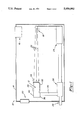
- FIG. 1 is a diagrammatic illustration of one operation of a holographic spectrometer according to the present invention.
- FIG. 2 is a cross-sectional view of the holographic spectrometer according to the present invention.
- Spectrometer system 10 is shown incorporating holographic spectrometer 12 according to a preferred embodiment of the present invention.
- Spectrometer system 10 is a rugged, portable system which is used to analyze the spectrum of gases at remote locations.
- Spectrometer system 10 includes a housing 14 having an intake port 18 including a filter and a fan for introducing a sample to be analyzed, and an exhaust port 20 for removing gases from the housing, alsoincluding a filter. Other means of introducing and exhausting a gas to be analyzed can be used.
- Ports 18 and 20 include means for sealing housing 14to make it substantially airtight.
- Housing 14 encloses a radiation source 16 and a holographic spectrometer 12.
- Radiation source 16 is generally a commercially available infrared source, such as a Nernst glower. Infrared radiation rays 22 from infrared source 16 are directed towards holographicspectrometer 12.
- Holographic spectrometer 12 includes an insulative piezoelectric crystal 40, generally in the shape of a rectangular block having attached at one short face a holographic lens 38, attached at one long face a detector array 36 and attached to opposite long faces vernier electrodes 32 and 34.
- Holographic lens 38 faces source 16 and receives infrared rays 22. Holographic lens 38 then disperses and directs rays 22 through infrared transparent piezoelectric block 40 towards detector array36 in a method which will be described hereunder.
- Housing 14 also includes bus 28, modem 26 and pulser 24 positioned in a manner as shown.
- Bus 28 may include telephone and power lines and connectsmodem 26 with remote telephone, computer and power sources (not shown) and with pulser 24.
- Bus 28 delivers power to pulser 24 which in turn activatesinfrared source 16.
- Pulser 24 is incorporated to increase the useable lifetime of source 16 and increase the safety of the device since the spectral analysis of the sample gas can be taken in a relatively short period of time. A typical pulse duration is generally a few seconds.
- Spectral data received by detector array 36 from holographic lens 38 is transmitted to modem 26 by line 30.
- Modem 26 transfers this data to a remote computer via telephone lines associated with bus 28 for analysis.
- the computer analyzes the spectral data to determine the molecular constituents of the sample gas, and can return commands by the telephone lines concerning pulse duration, range of frequencies to be detected, etc.
- airtight housing 14 is evacuated or provided with a referencegas.
- Detector array 36 is calibrated to a range of frequencies of infrared source 16 by well known means. Infrared source 16 then emits a pulse of infrared rays 22 towards holographic spectrometer 12 to develop a reference spectrum.
- the reference spectrum is generally substantially freefrom absorption of the IR radiation from source 16.
- a gas to be analyzed isthen introduced into housing 14 through intake port 18. Infrared source 16 again emits infrared rays 22 towards holographic spectrometer 12 as a pulse of the same duration as the reference pulse. Sample gases located within housing 14 interact with infrared rays 22 causing molecular absorption at certain wavelengths depending on what gases are present.
- Themolecules in the gas give off the absorbed IR radiation by other forms of energy, such as vibrational or rotational energy, which is not detected bydetector 36.
- Detector array 36 again detects the radiation at the same range of frequencies as the reference spectrum to develop an absorption spectrum.
- the remote computer connected to spectrometer system 10 via telephone lines in bus 28 compares the reference spectrum with the absorption spectrum to determine which wavelengths of infrared radiation have been absorbed and at what percentage absorption has occurred.
- the infrared radiation has been absorbed with known absorption characteristics of certain molecules, it can be determined what molecules, and thus what gases, are present in housing 14.Further, by comparing the intensity of transmitted radiation at the absorbed frequencies with the intensity transmitted at those frequencies of the reference spectrum, the percentage or amount of each of the gases present can be calculated.
- Holographic spectrometer 12 employs an infrared transparent insulative piezoelectric block 40 generally having a rectangular shape.
- piezoelectric block 40 is lithium-niobate, but can be of other materials having piezoelectric properties as well as being highly transparent to infrared radiation.
- piezoelectric block has a substantially square front face 50 having dimensions of 50 mm ⁇ 50 mm and two opposite side faces 52 and 54 having equal dimensionsof 50 mm ⁇ 150 mm.
- holographic lens 38 Positioned on front face 50, of piezoelectric block40, and facing infrared source 16, is holographic lens 38.
- piezoelectric block 40 On one of the side faces 54 a vernier electrode 34 is attached by means such as an adhesive. On an opposite side face 52 from side face 54 of piezoelectric block 40, is a second vernier electrode 32 and detector array 36. Electrode 32 and detector array 36 are also connected to piezoelectric block 40 by well known means such as an adhesive. It will be understood that piezoelectric block 40 can take on a variety of shapes and dimensionswithout departing from the scope of this invention.
- Holographic lens 38 is a highly dispersive holographic lens positioned on surface 50 of piezoelectric block 40.
- the holographic lens 38 itself is a recording of interference patterns on a holographic medium.
- the holographic medium for near-IR applications, can be a substrate of IR transparent material, such as glass, having a layer dispersed with a silver halide emulsion.
- the silver halide is photographically developed into a recorded interference pattern by interfering beams of light by means of a holographic process well-known in the art.
- This substrate is attached to piezoelectric block 40 by means of an IR transparent cement orthe like.
- the holographic lens 38 can also be etched onto piezoelectric block 40 by well known means in the art.
- the holographic lens can be made using computer generated holograms by methodsknown to those skilled in the art.
- holographic lens 38 has a very highchromatic aberration and acts as a grating to incident light. By knowing the range of frequencies of light incident on holographic lens 38, the direction and dispersion of the individual frequencies of the light can beaccurately determined.
- infrared radiation 22 incident upon holographic lens 38 at a specific point on lens 38 is separated into light of different component wavelengths and directed towards detector array 36.
- Infrared radiation 22 incident upon points 56 and 58 are separated into component wavelengths 44 and 46 having distinct separate wavelengths.
- the holographic lens 38 enables light incident upon the lens 38 at different points but having the same wavelength, to be directed towards detector array 36 at the same locations 42. Therefore, the dispersive effect of holographic lens 38 provides a means by which light having the same wavelengths incident anywhere on the lens will be directed towards the same location.
- the intersection location can be set at the detector array, thus effectively measuring the spectrum.
- Detector array 36 is separated into individual detector elements 48. By knowing the desired workable range of frequencies of rays 22 incident uponholographic lens 38, and by knowing the distance between holographic lens 38 and detector array 36, the recorded holographic image on lens 38 can imply that substantially only radiation of certain component wavelengths will impinge upon one detector element 48. Detector elements 48 are generally approximately 25 micrometers apart. Therefore, the resolution ofholographic spectrometer 12 is very high because detector array 36 has the sensitivity to separate minor spectral lines resulting from narrow ranged component wavelengths. Thus the high resolution enables the spectrometer to more accurately distinguish different molecular structures within the sample gas. Detector array 36 is generally a charge-coupled detector, but can be any suitable detector well known in the art. Detector array 36 is aself-scanning detector array enabling it to scan a wide range of frequencies.
- Electrodes 32 and 34 Attached to opposite faces of piezoelectric block 40 are vernier electrodes32 and 34. These electrodes are affixed to the front part of long faces 52 and 54 near face 50. Electrodes 32 and 34 are generally made of a suitableconductive material and are glued to piezoelectric block 40 by well known means. Vernier electrodes 32 and 34 enable piezoelectric fine tuning of radiation travelling from holograph lens 38 to detector array 36. A suitable voltage applied to electrodes 32 and 34 (by means not shown) willexpand or contract piezoelectric block 40 such that the direction of rays 44 and 46 is altered. Generally, a voltage potential of about 200 volts applied to the above-dimensioned piezoelectric block will shift component wavelengths from one detector element 48 to an adjacent detector element.
- piezoelectric adjustment of piezoelectric block 40 forces incident infrared rays 22 to contact holographic lens 38 at a location such that rays 44 and 46 are incident upon detector array 36 at the appropriate detector element 48.
- applying a voltage to vernier electrodes32 and 34 will expand or contract piezoelectric block 40 such that any specific wavelength will be directed to a desired detector element 48. This enables the holographic spectrometer 12 to accurately utilize a relatively large holographic lens 38 and still maintain high resolution and accuracy.
- holographic lens 38 receives infrared radiation 22 from source 16. Holographic lens 38 then disperses radiation 22 into component wavelengths and directs the individual wavelengths towards detector array 36. Separate component wavelengths incident upon detector array 36 impingeupon different detector elements 48. Therefore, an absorption spectrum taken by detector array 36 has high resolution because adjacent spectral lines impinge at different detector elements 48. Vernier electrodes 32 and34 compensate for misalignment of source 16 with spectrometer 12 by readjusting the individual wavelengths traveling between holographic lens 38 and detector array 36 to the desired location. Vernier electrodes 32 and 34 also enable the individual wavelengths travelling between holographic lens 38 and detector array 36 to be adjusted from one detectorelement to another. Therefore, the mid-frequency of the range of incident radiation can be moved up or down the detector array 36.
- the above described invention has the advantages of electronic fine tuning,making it very fast and accurate.
- the elimination of many of the prior art components enables the system to be much more rugged, compact and inexpensive.
- the elimination of focussing the radiation fromthe source onto an aperture eliminates the need for high precision servomechanisms, thus reducing the cost, size and fragility of the system.
- the use of the highly dispersive holographic lens 38 enables the system to have high accuracy and resolution due to the highly controllable dispersive effect of the recorded holographic image.
Landscapes
- Physics & Mathematics (AREA)
- Spectroscopy & Molecular Physics (AREA)
- General Physics & Mathematics (AREA)
- Spectrometry And Color Measurement (AREA)
- Investigating Or Analysing Materials By Optical Means (AREA)
- Analysing Materials By The Use Of Radiation (AREA)
Priority Applications (9)
| Application Number | Priority Date | Filing Date | Title |
|---|---|---|---|
| US07/508,436 US5050992A (en) | 1990-04-13 | 1990-04-13 | Dispersive holographic spectrometer |
| CA002038446A CA2038446C (en) | 1990-04-13 | 1991-03-18 | Dispersive holographic spectrometer |
| DE69110340T DE69110340T2 (de) | 1990-04-13 | 1991-04-09 | Dispersives Spektrometer mit Verwendung eines holographischen Beugungsgitters. |
| EP91303127A EP0452095B1 (en) | 1990-04-13 | 1991-04-09 | Dispersive holographic spectrometer |
| NO91911422A NO911422L (no) | 1990-04-13 | 1991-04-11 | Skillende holografisk spektrometer |
| FI911785A FI911785A (fi) | 1990-04-13 | 1991-04-12 | Dispersiv holografisk spektrometer. |
| KR1019910005875A KR950008824B1 (ko) | 1990-04-13 | 1991-04-12 | 방사선 분석용 홀로그래픽 분광계 및 이의 분석 방법 |
| JP3082578A JPH04225124A (ja) | 1990-04-13 | 1991-04-15 | 分散ホログラフィ分光計 |
| TW080103006A TW203650B (no) | 1990-04-13 | 1991-04-17 |
Applications Claiming Priority (1)
| Application Number | Priority Date | Filing Date | Title |
|---|---|---|---|
| US07/508,436 US5050992A (en) | 1990-04-13 | 1990-04-13 | Dispersive holographic spectrometer |
Publications (1)
| Publication Number | Publication Date |
|---|---|
| US5050992A true US5050992A (en) | 1991-09-24 |
Family
ID=24022741
Family Applications (1)
| Application Number | Title | Priority Date | Filing Date |
|---|---|---|---|
| US07/508,436 Expired - Lifetime US5050992A (en) | 1990-04-13 | 1990-04-13 | Dispersive holographic spectrometer |
Country Status (9)
| Country | Link |
|---|---|
| US (1) | US5050992A (no) |
| EP (1) | EP0452095B1 (no) |
| JP (1) | JPH04225124A (no) |
| KR (1) | KR950008824B1 (no) |
| CA (1) | CA2038446C (no) |
| DE (1) | DE69110340T2 (no) |
| FI (1) | FI911785A (no) |
| NO (1) | NO911422L (no) |
| TW (1) | TW203650B (no) |
Cited By (11)
| Publication number | Priority date | Publication date | Assignee | Title |
|---|---|---|---|---|
| WO1997033153A1 (en) * | 1996-03-05 | 1997-09-12 | Levine Michael S | Holographic gas analyzer |
| US5731874A (en) * | 1995-01-24 | 1998-03-24 | The Board Of Trustees Of The Leland Stanford Junior University | Discrete wavelength spectrometer |
| US5789733A (en) * | 1996-09-20 | 1998-08-04 | Motorola, Inc. | Smart card with contactless optical interface |
| US5900932A (en) * | 1993-07-02 | 1999-05-04 | Canon Information Systems, Inc. | Tristimulus template-type colorimeter |
| US20020071117A1 (en) * | 2000-11-10 | 2002-06-13 | Juichiro Ukon | Method for monitoring and/or controlling the status of a plasma in a plasma spectrometer and spectrometer for implementing such a method |
| US7376068B1 (en) * | 2000-08-19 | 2008-05-20 | Jehad Khoury | Nano-scale resolution holographic lens and pickup device |
| US7817274B2 (en) | 2007-10-05 | 2010-10-19 | Jingyun Zhang | Compact spectrometer |
| US8345226B2 (en) | 2007-11-30 | 2013-01-01 | Jingyun Zhang | Spectrometers miniaturized for working with cellular phones and other portable electronic devices |
| US20180058929A1 (en) * | 2016-08-25 | 2018-03-01 | Abl Ip Holding Llc | Fixture that provides light incorporating a reconfigurable spectrometer |
| US10365157B2 (en) | 2016-12-05 | 2019-07-30 | Abl Ip Holding Llc | Lighting device incorporating a hyperspectral imager as a reconfigurable sensing element |
| US10458844B2 (en) | 2016-08-25 | 2019-10-29 | Abl Ip Holding Llc | Reconfigurable optical fiber spectrometer in a lighting device |
Families Citing this family (1)
| Publication number | Priority date | Publication date | Assignee | Title |
|---|---|---|---|---|
| GB9200562D0 (en) * | 1992-01-11 | 1992-03-11 | Fisons Plc | Analytical device with polychromatic light source |
Citations (3)
| Publication number | Priority date | Publication date | Assignee | Title |
|---|---|---|---|---|
| US3794426A (en) * | 1972-12-08 | 1974-02-26 | Bendix Corp | Holographic spectrometer |
| US4735486A (en) * | 1985-03-29 | 1988-04-05 | Grumman Aerospace Corporation | Systems and methods for processing optical correlator memory devices |
| US4779984A (en) * | 1987-02-24 | 1988-10-25 | Hughes Aircraft Company | Method and apparatus for holographic spectrometry |
Family Cites Families (7)
| Publication number | Priority date | Publication date | Assignee | Title |
|---|---|---|---|---|
| JPS4916482A (no) * | 1972-05-22 | 1974-02-13 | ||
| US4678332A (en) * | 1984-02-21 | 1987-07-07 | Dan Rock | Broadband spectrometer with fiber optic reformattor |
| JPS61160715A (ja) * | 1985-01-09 | 1986-07-21 | Canon Inc | 焦点距離可変レンズ |
| JPS62121323A (ja) * | 1985-11-22 | 1987-06-02 | Hitachi Ltd | 偏光測定装置 |
| US4790654A (en) * | 1987-07-17 | 1988-12-13 | Trw Inc. | Spectral filter |
| US4815849A (en) * | 1987-12-30 | 1989-03-28 | Hewlett-Packard Company | Spectrometer using concave holographic diffraction grating |
| GB2219853A (en) * | 1988-06-14 | 1989-12-20 | Plessey Co Plc | A spectral filter |
-
1990
- 1990-04-13 US US07/508,436 patent/US5050992A/en not_active Expired - Lifetime
-
1991
- 1991-03-18 CA CA002038446A patent/CA2038446C/en not_active Expired - Fee Related
- 1991-04-09 DE DE69110340T patent/DE69110340T2/de not_active Expired - Fee Related
- 1991-04-09 EP EP91303127A patent/EP0452095B1/en not_active Expired - Lifetime
- 1991-04-11 NO NO91911422A patent/NO911422L/no unknown
- 1991-04-12 FI FI911785A patent/FI911785A/fi not_active Application Discontinuation
- 1991-04-12 KR KR1019910005875A patent/KR950008824B1/ko active IP Right Grant
- 1991-04-15 JP JP3082578A patent/JPH04225124A/ja active Pending
- 1991-04-17 TW TW080103006A patent/TW203650B/zh active
Patent Citations (3)
| Publication number | Priority date | Publication date | Assignee | Title |
|---|---|---|---|---|
| US3794426A (en) * | 1972-12-08 | 1974-02-26 | Bendix Corp | Holographic spectrometer |
| US4735486A (en) * | 1985-03-29 | 1988-04-05 | Grumman Aerospace Corporation | Systems and methods for processing optical correlator memory devices |
| US4779984A (en) * | 1987-02-24 | 1988-10-25 | Hughes Aircraft Company | Method and apparatus for holographic spectrometry |
Cited By (17)
| Publication number | Priority date | Publication date | Assignee | Title |
|---|---|---|---|---|
| US5900932A (en) * | 1993-07-02 | 1999-05-04 | Canon Information Systems, Inc. | Tristimulus template-type colorimeter |
| US5731874A (en) * | 1995-01-24 | 1998-03-24 | The Board Of Trustees Of The Leland Stanford Junior University | Discrete wavelength spectrometer |
| WO1997033153A1 (en) * | 1996-03-05 | 1997-09-12 | Levine Michael S | Holographic gas analyzer |
| US5854685A (en) * | 1996-03-05 | 1998-12-29 | Levine; Michael S. | Holographic gas analyzer utilizing holographic optics |
| US5789733A (en) * | 1996-09-20 | 1998-08-04 | Motorola, Inc. | Smart card with contactless optical interface |
| US7376068B1 (en) * | 2000-08-19 | 2008-05-20 | Jehad Khoury | Nano-scale resolution holographic lens and pickup device |
| US20020071117A1 (en) * | 2000-11-10 | 2002-06-13 | Juichiro Ukon | Method for monitoring and/or controlling the status of a plasma in a plasma spectrometer and spectrometer for implementing such a method |
| US6943879B2 (en) * | 2000-11-10 | 2005-09-13 | Jobin Yvon, S.A. | Method for monitoring and/or controlling the status of a plasma in a plasma spectrometer and spectrometer for implementing such a method |
| US7817274B2 (en) | 2007-10-05 | 2010-10-19 | Jingyun Zhang | Compact spectrometer |
| US8345226B2 (en) | 2007-11-30 | 2013-01-01 | Jingyun Zhang | Spectrometers miniaturized for working with cellular phones and other portable electronic devices |
| US8537343B2 (en) | 2007-11-30 | 2013-09-17 | Jingyun Zhang | Spectrometer miniaturized for working with cellular phones and other portable electronic devices |
| US20180058929A1 (en) * | 2016-08-25 | 2018-03-01 | Abl Ip Holding Llc | Fixture that provides light incorporating a reconfigurable spectrometer |
| US10281326B2 (en) * | 2016-08-25 | 2019-05-07 | Abl Ip Holding Llc | Fixture that provides light incorporating a reconfigurable spectrometer |
| US10458844B2 (en) | 2016-08-25 | 2019-10-29 | Abl Ip Holding Llc | Reconfigurable optical fiber spectrometer in a lighting device |
| US10753792B2 (en) | 2016-08-25 | 2020-08-25 | Abl Ip Holding Llc | Reconfigurable optical fiber spectrometer in a lighting device |
| US10365157B2 (en) | 2016-12-05 | 2019-07-30 | Abl Ip Holding Llc | Lighting device incorporating a hyperspectral imager as a reconfigurable sensing element |
| US10591355B2 (en) | 2016-12-05 | 2020-03-17 | Abl Ip Holding Llc | Lighting device incorporating a hyperspectral imager as a reconfigurable sensing element |
Also Published As
| Publication number | Publication date |
|---|---|
| EP0452095B1 (en) | 1995-06-14 |
| CA2038446C (en) | 1995-04-11 |
| NO911422L (no) | 1991-10-14 |
| NO911422D0 (no) | 1991-04-11 |
| FI911785A (fi) | 1991-10-14 |
| DE69110340T2 (de) | 1996-03-07 |
| EP0452095A1 (en) | 1991-10-16 |
| DE69110340D1 (de) | 1995-07-20 |
| TW203650B (no) | 1993-04-11 |
| KR950008824B1 (ko) | 1995-08-08 |
| JPH04225124A (ja) | 1992-08-14 |
| FI911785A0 (fi) | 1991-04-12 |
| KR920005760A (ko) | 1992-04-03 |
Similar Documents
| Publication | Publication Date | Title |
|---|---|---|
| US5050992A (en) | Dispersive holographic spectrometer | |
| US6687007B1 (en) | Common path interferometer for spectral image generation | |
| US5351127A (en) | Surface plasmon resonance measuring instruments | |
| US4070111A (en) | Rapid scan spectrophotometer | |
| US5731874A (en) | Discrete wavelength spectrometer | |
| US7528958B2 (en) | Optical scanner for measuring sheet properties | |
| US7034935B1 (en) | High performance miniature spectrometer | |
| EP0449335A2 (en) | Interferometer | |
| US3791737A (en) | Spectrometer in which a desired number of spectral lines are focused at one fixed output slit | |
| US5285261A (en) | Dual interferometer spectroscopic imaging system | |
| US3437411A (en) | Optical null spectrophotometer | |
| US6853449B2 (en) | Programmable diffraction grating sensor | |
| US3578866A (en) | Frequency modulated optical spectrometer | |
| JP4237363B2 (ja) | 赤外分光装置 | |
| US4850706A (en) | Low profile spectral analysis system | |
| US5406377A (en) | Spectroscopic imaging system using a pulsed electromagnetic radiation source and an interferometer | |
| US4779984A (en) | Method and apparatus for holographic spectrometry | |
| JPS59164945A (ja) | 光学分析計器 | |
| US6831747B2 (en) | Spectrometry and filtering with high rejection of stray light | |
| US7515319B2 (en) | Lens-less spectrometer | |
| US4172637A (en) | Common beam aperture for dual beam spectrophotometers | |
| Kawazumi et al. | Laser-based photoacoustic densitometer for two-dimensional scanning of thin-layer chromatographic plates | |
| RU2036418C1 (ru) | Устройство для определения толщины и оптических свойств слоев в процессе их формирования | |
| Fotiou et al. | Photothermal deflection densitometer with pulsed-UV laser excitation | |
| SU1619015A1 (ru) | Способ контрол толщины материала |
Legal Events
| Date | Code | Title | Description |
|---|---|---|---|
| AS | Assignment |
Owner name: HUGHES AIRCRAFT COMPANY, A CORP. OF DELAWARE, CALI Free format text: ASSIGNMENT OF ASSIGNORS INTEREST.;ASSIGNORS:DRUMMOND, JAMES E.;SHIH, I-FU;REEL/FRAME:005282/0766;SIGNING DATES FROM 19900403 TO 19900406 |
|
| STCF | Information on status: patent grant |
Free format text: PATENTED CASE |
|
| FEPP | Fee payment procedure |
Free format text: PAYOR NUMBER ASSIGNED (ORIGINAL EVENT CODE: ASPN); ENTITY STATUS OF PATENT OWNER: LARGE ENTITY |
|
| REMI | Maintenance fee reminder mailed | ||
| FPAY | Fee payment |
Year of fee payment: 4 |
|
| SULP | Surcharge for late payment | ||
| REFU | Refund |
Free format text: REFUND - SURCHARGE FOR LATE PAYMENT, LARGE ENTITY (ORIGINAL EVENT CODE: R186); ENTITY STATUS OF PATENT OWNER: LARGE ENTITY Free format text: REFUND - PAYMENT OF MAINTENANCE FEE, 4TH YEAR, LARGE ENTITY (ORIGINAL EVENT CODE: R183); ENTITY STATUS OF PATENT OWNER: LARGE ENTITY |
|
| FPAY | Fee payment |
Year of fee payment: 8 |
|
| FPAY | Fee payment |
Year of fee payment: 12 |
|
| AS | Assignment |
Owner name: HE HOLDINGS, INC., A DELAWARE CORP., CALIFORNIA Free format text: CHANGE OF NAME;ASSIGNOR:HUGHES AIRCRAFT COMPANY, A CORPORATION OF THE STATE OF DELAWARE;REEL/FRAME:016087/0541 Effective date: 19971217 Owner name: RAYTHEON COMPANY, MASSACHUSETTS Free format text: MERGER;ASSIGNOR:HE HOLDINGS, INC. DBA HUGHES ELECTRONICS;REEL/FRAME:016116/0506 Effective date: 19971217 |