US5040221A - Compact electroacoustical transducing with flat conducting tinsel leads crimped to voice coil ends - Google Patents
Compact electroacoustical transducing with flat conducting tinsel leads crimped to voice coil ends Download PDFInfo
- Publication number
- US5040221A US5040221A US06/798,559 US79855985A US5040221A US 5040221 A US5040221 A US 5040221A US 79855985 A US79855985 A US 79855985A US 5040221 A US5040221 A US 5040221A
- Authority
- US
- United States
- Prior art keywords
- voice coil
- basket
- flat
- cone
- tinsel
- Prior art date
- Legal status (The legal status is an assumption and is not a legal conclusion. Google has not performed a legal analysis and makes no representation as to the accuracy of the status listed.)
- Expired - Fee Related
Links
Images
Classifications
-
- H—ELECTRICITY
- H04—ELECTRIC COMMUNICATION TECHNIQUE
- H04R—LOUDSPEAKERS, MICROPHONES, GRAMOPHONE PICK-UPS OR LIKE ACOUSTIC ELECTROMECHANICAL TRANSDUCERS; ELECTRIC HEARING AIDS; PUBLIC ADDRESS SYSTEMS
- H04R9/00—Transducers of moving-coil, moving-strip, or moving-wire type
- H04R9/06—Loudspeakers
-
- H—ELECTRICITY
- H04—ELECTRIC COMMUNICATION TECHNIQUE
- H04R—LOUDSPEAKERS, MICROPHONES, GRAMOPHONE PICK-UPS OR LIKE ACOUSTIC ELECTROMECHANICAL TRANSDUCERS; ELECTRIC HEARING AIDS; PUBLIC ADDRESS SYSTEMS
- H04R9/00—Transducers of moving-coil, moving-strip, or moving-wire type
- H04R9/02—Details
- H04R9/04—Construction, mounting, or centering of coil
- H04R9/045—Mounting
Definitions
- the present invention relates in general to compact electro-acoustical transducing and more particularly concerns a novel loudspeaker driver that affords high electro-acoustical transducing performance in a compact structure that is relatively easy and inexpensive to fabricate.
- a loudspeaker driver having a molded plastic basket made of thermoplastic polyester with glass fill and a front pole plate of low reluctance magnetic material molded into the base of the basket with a keyed central bore.
- the motor structure is located behind the front pole plate.
- the edge of the spider that resiliently supports the voice coil is fastened to an annular surface inside the basket.
- a low resistance single layer anodized aluminum rectangular wire voice coil is wound on a slit anodized aluminum bob-bin. There is a notch in the adjacent pole plate for the return length of the voice coil wire.
- This loudspeaker driver exhibits excellent electro-acoustical and mechanical characteristics and operates satisfactorily under a wide range of environmental conditions.
- a loudspeaker driver basket having the motor structure located in front of the cone with the spider behind the motor structure resiliently supporting the rear edge of the voice coil.
- the basket is preferably made of plastic and is formed with rivets ultrasonically bonding terminals to the basket.
- Flat flexible tinsel leads are brought out through slits in the cone to the terminals.
- the basket is formed with acoustically transparent structurally supporting radial ribs in which a cup of low reluctance magnetic material is molded formed with an axial notch on the inside surface to accommodating a flexible voice coil lead.
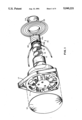
- FIG. 1 is a mostly exploded view of a loudspeaker driver according to the invention
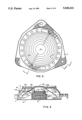
- FIG. 2 is a plan rear view of an embodiment of the invention
- FIG. 3 is a sectional view through section 3--3 of FIG. 2;
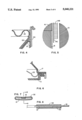
- FIG. 4 is an enlarged detail view illustrating the junction among spider, cone and voice coil support
- FIG. 5 is an enlarged view of a portion of the annular motor gap
- FIG. 6 is a sectional view through section 6--6 of FIG. 2;
- FIG. 7 is a transverse sectional view of the tinsel-voice coil joint.
- FIG. 8 is a sectional view through section 8--8 of FIG. 7;
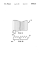
- FIG. 9 is a fragmentary plan view of a preferred form of crimp stock according to the invention.
- FIG. 10 is a fragmentary elevation view of the crimp stock of FIG. 9.
- FIGS. 1-3 there are shown respectively a mostly exploded view, rear plan view and sectional view through section 3--3 of FIG. 2, of a loudspeaker driver according to the invention having a plastic basket front portion 11 covered by a circular scrim 12 and supporting a rearwardly opening molded-in cup-shaped front pole piece 13 formed with an annular recess 13A for accommodating the front edge of voice coil assembly 14 and an axial recess for accommodating the axial lead 14A from the front end of voice coil 14B.
- Voice coil 14B is supported on an axial slit cylindrical aluminum sheet.
- a neodymium circular disk magnet 15 is sandwiched between the closed end of front pole piece 13 and circular disk rear pole plate coacting with the front cup-shaped pole piece 13 to define an annular gap for accommodating voice coil assembly 14 with a radial magnetic field developed between rear pole plate 16 and the cylindrical wall of front pole piece 13.
- a plastic basket rear portion 17 mates with plastic basket front portion 11 and is ultrasonically bonded thereto.
- Plastic basket rear portion 17 is formed with studs 17A comprising plastic rivets that secure terminals 18 to plastic basket rear portion 17.
- Terminals 18 are connected to respective ones of flat tinsel leds 21 crimped at the other end to a respective voice coil lead.
- Flat tinsel conducting leads 21 are brought out through slits 22A oriented in a plane perpendicular to the axis of the loudspeaker assembly.
- the annular edge of cone 22 is clamped between mating annular surfaces of plastic basket front and rear portions 11 and 17.
- Spider 23 resiliently supports the rear edge of voice coil assembly 14 and has its outer annular edge ultrasonically bonded to the recessed annular rim 17B.
- a dust cover 24 completes the assembly.
- FIG. 4 there is shown an enlarged view illustrating the junction among spider 23, cone 22 and voice coil support 14C.
- FIG. 5 there is shown an enlarged view of a portion of the annular motor gap between circular disk magnet 15, circular disk rear pole plate 16 and the upstanding circular wall of front pole piece 13.
- FIG. 6 there is shown a view through section 6--6 of FIG. 2 illustrating the manner in which plastic basket front and rear portions 11 and 17 are fastened together with the annular rim of cone 22 therebetween.
- FIG. 7 there is shown a transverse sectional view of the tinsel-voice coil joint illustrating the connection between voice coil wire and flat tinsel lead
- FIG. 8 is a view through section 8--8 of FIG. 7.
- Tinsel lead 21 and voice coil wire 31 are in overlapping relationship surrounded by crimp band 32 that is pressed flat as shown to insure good electrical and mechanical contact with tinsel 21.
- crimp band 32 made of a preferred form of crimp stock.
- the preferred crimp stock is of sawtooth cross section having peaks such as 32A above valleys such as 32B.
- the material is half-hard brass finished with thick tin plate of plating thickness within the range of 0.001 to 0.0003 inches.
- the thickness from the base line 32C to a peak such as 32A is typically about 0.008" and the distance from base 32C to a valley such as 32B is typically about 0.00035".
- the length of a crimp 32 is typically about 0.115".
- This aspect of the invention solved a serious problem.
- the lead resistance varied with cone motion, introducing an undesired variable resistance modulation to the reproduced sound signal. It was discovered that the cause of this problem was variation in the resistance in the crimped connection.
- the crimp stock structure shown in FIGS. 9 and 10 overcame this problem. This structure provides significantly greater surface area for establishing contact with the conducting lead 31. Wire 31 stretches around points, such as 32A, past any insulation in the wire to establish a low resistance contact. The fine structure that is at most 4 mils peak-to-valley avoids destroying wire 31 while establishing this good contact.
Landscapes
- Physics & Mathematics (AREA)
- Engineering & Computer Science (AREA)
- Acoustics & Sound (AREA)
- Signal Processing (AREA)
- Audible-Bandwidth Dynamoelectric Transducers Other Than Pickups (AREA)
Abstract
A loudspeaker driver has a plastic basket having front and rear portions. The front portion is formed with six radial ribs extending between a central motor cup support and an annular rim. A cup-shaped front pole piece is molded into the pole support and formed with an axial groove for accommodating an axial lead extending from the front end of a voice coil that moves axially in a gap between the circumferential wall of the front pole plate and a circular rear pole plate and circular disk neodymium disk magnet sandwiched between the rear pole plate and the closed end of the front pole plate. Flat tinsel leads are crimped to ends of the voice coil and brought out through slits in the cone to terminals in opposite sides of the rear portion of the basket. The circumferential edge of the cone is clamped between the front and rear portions of the basket and ultrasonically bonded to an annular surface on the rear of the front portion. The rear end of the cone is cemented to the rear of the voice coil support just forward of where the spider collar is fastened to the voice coil support. The circumferential edge of the spider is ultrasonically bonded to a depressed annular rim at the rear of the rear portion of the basket.
Description
The present invention relates in general to compact electro-acoustical transducing and more particularly concerns a novel loudspeaker driver that affords high electro-acoustical transducing performance in a compact structure that is relatively easy and inexpensive to fabricate.
For background reference is made to U.S. Pat. No. 4,061,890 entitled LOUDSPEAKER WITH SINGLE LAYER RECTANGULAR WIRE VOICE COIL WOUND ON SLIT METAL BOBBIN WITH A NOTCH IN THE ADJACENT POLE PLATE of Thomas A. Froeschle granted Dec. 6, 1977, and U.S. Pat. No. 4,158,756 entitled DYNAMIC LOUDSPEAKER WITH PLASTIC BASKET ENCAPSULATING FRONT POLE PLATE of William J. Keezer granted June 19, 1979. These patents disclose a loudspeaker driver embodied in the commercially available BOSE 901 loudspeaker system and the Delco-GM-Bose music system. These patents disclose a loudspeaker driver having a molded plastic basket made of thermoplastic polyester with glass fill and a front pole plate of low reluctance magnetic material molded into the base of the basket with a keyed central bore. The motor structure is located behind the front pole plate. The edge of the spider that resiliently supports the voice coil is fastened to an annular surface inside the basket. A low resistance single layer anodized aluminum rectangular wire voice coil is wound on a slit anodized aluminum bob-bin. There is a notch in the adjacent pole plate for the return length of the voice coil wire. This loudspeaker driver exhibits excellent electro-acoustical and mechanical characteristics and operates satisfactorily under a wide range of environmental conditions.
It is an important object of this invention to provide an improved loudspeaker driver.
According to the invention, there is a loudspeaker driver basket having the motor structure located in front of the cone with the spider behind the motor structure resiliently supporting the rear edge of the voice coil. The basket is preferably made of plastic and is formed with rivets ultrasonically bonding terminals to the basket. Flat flexible tinsel leads are brought out through slits in the cone to the terminals. The basket is formed with acoustically transparent structurally supporting radial ribs in which a cup of low reluctance magnetic material is molded formed with an axial notch on the inside surface to accommodating a flexible voice coil lead.
Numerous other features, objects and advantages of the invention will become apparent from the following specification when read in connection with the accompanying drawing in which:
FIG. 1 is a mostly exploded view of a loudspeaker driver according to the invention;
FIG. 2 is a plan rear view of an embodiment of the invention;
FIG. 3 is a sectional view through section 3--3 of FIG. 2;
FIG. 4 is an enlarged detail view illustrating the junction among spider, cone and voice coil support;
FIG. 5 is an enlarged view of a portion of the annular motor gap;
FIG. 6 is a sectional view through section 6--6 of FIG. 2;
FIG. 7 is a transverse sectional view of the tinsel-voice coil joint; and
FIG. 8 is a sectional view through section 8--8 of FIG. 7;
FIG. 9 is a fragmentary plan view of a preferred form of crimp stock according to the invention; and
FIG. 10 is a fragmentary elevation view of the crimp stock of FIG. 9.
With reference now to the drawing and more particularly FIGS. 1-3 thereof, there are shown respectively a mostly exploded view, rear plan view and sectional view through section 3--3 of FIG. 2, of a loudspeaker driver according to the invention having a plastic basket front portion 11 covered by a circular scrim 12 and supporting a rearwardly opening molded-in cup-shaped front pole piece 13 formed with an annular recess 13A for accommodating the front edge of voice coil assembly 14 and an axial recess for accommodating the axial lead 14A from the front end of voice coil 14B. Voice coil 14B is supported on an axial slit cylindrical aluminum sheet.
A neodymium circular disk magnet 15 is sandwiched between the closed end of front pole piece 13 and circular disk rear pole plate coacting with the front cup-shaped pole piece 13 to define an annular gap for accommodating voice coil assembly 14 with a radial magnetic field developed between rear pole plate 16 and the cylindrical wall of front pole piece 13.
A plastic basket rear portion 17 mates with plastic basket front portion 11 and is ultrasonically bonded thereto. Plastic basket rear portion 17 is formed with studs 17A comprising plastic rivets that secure terminals 18 to plastic basket rear portion 17. Terminals 18 are connected to respective ones of flat tinsel leds 21 crimped at the other end to a respective voice coil lead.
Flat tinsel conducting leads 21 are brought out through slits 22A oriented in a plane perpendicular to the axis of the loudspeaker assembly. The annular edge of cone 22 is clamped between mating annular surfaces of plastic basket front and rear portions 11 and 17.
Spider 23 resiliently supports the rear edge of voice coil assembly 14 and has its outer annular edge ultrasonically bonded to the recessed annular rim 17B. A dust cover 24 completes the assembly.
Referring to FIG. 4, there is shown an enlarged view illustrating the junction among spider 23, cone 22 and voice coil support 14C.
Referring to FIG. 5, there is shown an enlarged view of a portion of the annular motor gap between circular disk magnet 15, circular disk rear pole plate 16 and the upstanding circular wall of front pole piece 13.
Referring to FIG. 6, there is shown a view through section 6--6 of FIG. 2 illustrating the manner in which plastic basket front and rear portions 11 and 17 are fastened together with the annular rim of cone 22 therebetween.
Referring to FIG. 7, there is shown a transverse sectional view of the tinsel-voice coil joint illustrating the connection between voice coil wire and flat tinsel lead, and FIG. 8 is a view through section 8--8 of FIG. 7. Tinsel lead 21 and voice coil wire 31 are in overlapping relationship surrounded by crimp band 32 that is pressed flat as shown to insure good electrical and mechanical contact with tinsel 21. There is a small void volume 33 visible in FIG. 8 between coil wire 31 and crimp band 32 to afford space for coil wire 31 to move without damage from crimp band 32.
Referring to FIGS. 9 and 10, there are shown fragmentary plan and elevation views, respectively, of crimp band 32 made of a preferred form of crimp stock. As best seen in FIG. 10, the preferred crimp stock is of sawtooth cross section having peaks such as 32A above valleys such as 32B. Typically the material is half-hard brass finished with thick tin plate of plating thickness within the range of 0.001 to 0.0003 inches. The thickness from the base line 32C to a peak such as 32A is typically about 0.008" and the distance from base 32C to a valley such as 32B is typically about 0.00035". The length of a crimp 32 is typically about 0.115".
This aspect of the invention solved a serious problem. When using flat crimp stock, it was discovered that the lead resistance varied with cone motion, introducing an undesired variable resistance modulation to the reproduced sound signal. It was discovered that the cause of this problem was variation in the resistance in the crimped connection. The crimp stock structure shown in FIGS. 9 and 10 overcame this problem. This structure provides significantly greater surface area for establishing contact with the conducting lead 31. Wire 31 stretches around points, such as 32A, past any insulation in the wire to establish a low resistance contact. The fine structure that is at most 4 mils peak-to-valley avoids destroying wire 31 while establishing this good contact.
There has been described a novel full-range loudspeaker driver characterized by excellent electro-acoustical and mechanical properties that is especially compact and produceable on a mass production basis. It is evident that those skilled in the art may now make numerous uses and modifications of and departures from the specific embodiments described herein without departing from the inventive concepts. Consequently, the invention is to be construed as embracing each and every novel feature and novel combination of features present in or possessed by the apparatus and techniques herein disclosed and limited solely by the spirit and scope of the appended claims.
Claims (2)
1. A loudspeaker driver comprising,
basket means for supporting components of said loudspeaker driver,
first and second terminals secured to said basket means,
voice coil means having first and second ends,
means for supporting said voice coil mans in said basket means,
first and second flat tinsel conducting leads interconnecting said first and second terminals with said first and second ends respectively of said voice coil means,
wherein said loudspeaker driver includes a cone secured to said voice coil means supported in said basket means and said cone is formed with first and second slits near said voice coil means,
said first and second flat tinsel leads passing through said first and second slits respectively,
and flat crimp means for mechanically and electrically bonding said first and second flat tinsel conducting leads to said first and second voice coil ends respectively,
wherein said flat crimp means comprises crimp stock of conducting material of the order of 10 mils thick formed with a fine pointed pattern that is at most 4 mils peak-to-valley in at least one surface thereof for snugly engaging a voice coil end.
2. A loudspeaker drive comprising,
basket means for supporting components of said loudspeaker driver,
first and second terminals secured to said basket means,
voice coil means having first and second ends,
means for supporting said voice coil means in said basket means,
first and second flat tinsel conducting leads interconnecting said first and second terminals with said first and second ends respectively of said voice coil means,
flat crimp means for mechanically and electrically bonding said first and second flat tinsel conducting leads to said first and second voice coil ends respectively,
wherein said loudspeaker driver includes a cone secured to said voice coil means supported in said basket means and said cone is formed with first and second slits near said voice coil means,
said first and second flat tinsel leads passing through said first and second slits respectively,
wherein said first and second flat tinsel leads extend radially along said cone from said first and second voice coil ends respectively through said first and second slits respectively to said first and second terminals respectively,
and wherein said flat crimp means comprises crimp stock of conducting material of the order of 10 mils thick formed with a fine pointed pattern that is at most 4 mils peak-to-valley on one surface thereof for establishing good electrical and mechanical contact with a voice coil end.
Priority Applications (4)
| Application Number | Priority Date | Filing Date | Title |
|---|---|---|---|
| US06/798,559 US5040221A (en) | 1985-11-15 | 1985-11-15 | Compact electroacoustical transducing with flat conducting tinsel leads crimped to voice coil ends |
| DE19863638693 DE3638693A1 (en) | 1985-11-15 | 1986-11-13 | Compact electroacoustic transformer |
| DE19863638727 DE3638727C2 (en) | 1985-11-15 | 1986-11-13 | Compact electro-acoustic transmitter |
| JP61272739A JP2685175B2 (en) | 1985-11-15 | 1986-11-15 | Small electroacoustic transducer |
Applications Claiming Priority (1)
| Application Number | Priority Date | Filing Date | Title |
|---|---|---|---|
| US06/798,559 US5040221A (en) | 1985-11-15 | 1985-11-15 | Compact electroacoustical transducing with flat conducting tinsel leads crimped to voice coil ends |
Publications (1)
| Publication Number | Publication Date |
|---|---|
| US5040221A true US5040221A (en) | 1991-08-13 |
Family
ID=25173711
Family Applications (1)
| Application Number | Title | Priority Date | Filing Date |
|---|---|---|---|
| US06/798,559 Expired - Fee Related US5040221A (en) | 1985-11-15 | 1985-11-15 | Compact electroacoustical transducing with flat conducting tinsel leads crimped to voice coil ends |
Country Status (1)
| Country | Link |
|---|---|
| US (1) | US5040221A (en) |
Cited By (26)
| Publication number | Priority date | Publication date | Assignee | Title |
|---|---|---|---|---|
| US5426707A (en) * | 1990-10-09 | 1995-06-20 | Laine B. V. | Electrodynamic loudspeaker with cooling arrangement |
| US5748760A (en) * | 1995-04-18 | 1998-05-05 | Harman International Industries, Inc. | Dual coil drive with multipurpose housing |
| US5802191A (en) * | 1995-01-06 | 1998-09-01 | Guenther; Godehard A. | Loudspeakers, systems, and components thereof |
| US5832438A (en) * | 1995-02-08 | 1998-11-03 | Sun Micro Systems, Inc. | Apparatus and method for audio computing |
| US5937074A (en) * | 1996-08-12 | 1999-08-10 | Carver; Robert W. | High back emf, high pressure subwoofer having small volume cabinet, low frequency cutoff and pressure resistant surround |
| US6130954A (en) * | 1996-01-02 | 2000-10-10 | Carver; Robert W. | High back-emf, high pressure subwoofer having small volume cabinet, low frequency cutoff and pressure resistant surround |
| US20020106101A1 (en) * | 2001-02-03 | 2002-08-08 | Kh Technology Corporation | Loudspeaker assembly |
| US6496590B2 (en) * | 2000-12-08 | 2002-12-17 | Jl Audio, Inc. | Loudspeaker with improved diaphragm |
| US6611606B2 (en) | 2000-06-27 | 2003-08-26 | Godehard A. Guenther | Compact high performance speaker |
| US6654476B1 (en) | 1999-08-13 | 2003-11-25 | Godehard A. Guenther | Low cost broad range loudspeaker and system |
| US20040071308A1 (en) * | 2000-08-14 | 2004-04-15 | Guenther Godehard A. | Low cost broad range loudspeaker and system |
| US6731773B1 (en) | 2002-11-01 | 2004-05-04 | Stillwater Designs And Audio, Inc. | Dual basket speaker with replaceable, self-aligning cone assembly and super ventilated pole piece |
| US20060159301A1 (en) * | 2004-09-09 | 2006-07-20 | Guenther Godehard A | Loudspeakers and systems |
| US20060215870A1 (en) * | 2000-06-27 | 2006-09-28 | Guenther Godehard A | Low profile speaker and system |
| US20060239493A1 (en) * | 1998-11-13 | 2006-10-26 | Guenther Godehard A | Low cost motor design for rare-earth-magnet loudspeakers |
| US20070223777A1 (en) * | 2006-03-22 | 2007-09-27 | Harman International Industries Incorporated | Loudspeaker having an interlocking magnet structure |
| US20080292117A1 (en) * | 2007-05-23 | 2008-11-27 | Soundmatters International Inc. | Loudspeaker and electronic devices incorporating same |
| US20090074227A1 (en) * | 2007-09-17 | 2009-03-19 | Renner G Stewart | Crimping tinsel leads |
| US20090123005A1 (en) * | 2007-11-14 | 2009-05-14 | Harman International Industries, Incorporated | Multiple magnet loudspeaker |
| US20090304222A1 (en) * | 1999-08-13 | 2009-12-10 | Guenther Godehard A | Low cost motor design for rare-earth-magnet loudspeakers |
| US20110135140A1 (en) * | 2009-12-07 | 2011-06-09 | Alpine Electronics, Inc. | Speaker apparatus |
| US20130182885A1 (en) * | 2012-01-16 | 2013-07-18 | Onkyo Corporation | Electrodynamic speaker and method for manufacturing the same |
| WO2015172300A1 (en) * | 2014-05-12 | 2015-11-19 | 刘骏涛 | Mini-speaker |
| US9445201B2 (en) | 2013-11-21 | 2016-09-13 | Harman International Industries, Inc. | Inverted dual coil transducer |
| WO2017015228A1 (en) * | 2015-07-20 | 2017-01-26 | Sonos, Inc. | Voice coil wire configurations |
| US20200092654A1 (en) * | 2018-09-14 | 2020-03-19 | Harman International Industries, Incorporated | Inverted motor transducer with front spider |
Citations (10)
| Publication number | Priority date | Publication date | Assignee | Title |
|---|---|---|---|---|
| GB647396A (en) * | 1948-11-02 | 1950-12-13 | Herbert Walter Gerard Grotefel | Improvements in or relating to terminal connections for the voice coils of loudspeakers |
| GB776280A (en) * | 1954-05-26 | 1957-06-05 | Cole E K Ltd | Improvements in or relating to moving coil loudspeakers and microphones |
| US3129995A (en) * | 1960-11-14 | 1964-04-21 | Hi Shear Corp | Electrical connector |
| US3358088A (en) * | 1964-06-05 | 1967-12-12 | Cts Corp | Electromechanical transducer |
| US3525127A (en) * | 1968-06-21 | 1970-08-25 | John D Hollingsworth | Foundation wire for card cylinders |
| US3616529A (en) * | 1967-08-31 | 1971-11-02 | Philips Corp | Transducer and method of making same |
| US3711659A (en) * | 1971-01-20 | 1973-01-16 | G Bremseth | Loudspeaker voice coils |
| US4151364A (en) * | 1976-09-29 | 1979-04-24 | Ellis J Scott | Electrical connectors and methods of connecting electrical conductors |
| US4158756A (en) * | 1976-08-27 | 1979-06-19 | Bose Corporation | Dynamic loudspeaker with plastic basket encapsulating front pole plate |
| US4539442A (en) * | 1982-12-24 | 1985-09-03 | International Standard Electric Corporation | Loudspeaker |
-
1985
- 1985-11-15 US US06/798,559 patent/US5040221A/en not_active Expired - Fee Related
Patent Citations (10)
| Publication number | Priority date | Publication date | Assignee | Title |
|---|---|---|---|---|
| GB647396A (en) * | 1948-11-02 | 1950-12-13 | Herbert Walter Gerard Grotefel | Improvements in or relating to terminal connections for the voice coils of loudspeakers |
| GB776280A (en) * | 1954-05-26 | 1957-06-05 | Cole E K Ltd | Improvements in or relating to moving coil loudspeakers and microphones |
| US3129995A (en) * | 1960-11-14 | 1964-04-21 | Hi Shear Corp | Electrical connector |
| US3358088A (en) * | 1964-06-05 | 1967-12-12 | Cts Corp | Electromechanical transducer |
| US3616529A (en) * | 1967-08-31 | 1971-11-02 | Philips Corp | Transducer and method of making same |
| US3525127A (en) * | 1968-06-21 | 1970-08-25 | John D Hollingsworth | Foundation wire for card cylinders |
| US3711659A (en) * | 1971-01-20 | 1973-01-16 | G Bremseth | Loudspeaker voice coils |
| US4158756A (en) * | 1976-08-27 | 1979-06-19 | Bose Corporation | Dynamic loudspeaker with plastic basket encapsulating front pole plate |
| US4151364A (en) * | 1976-09-29 | 1979-04-24 | Ellis J Scott | Electrical connectors and methods of connecting electrical conductors |
| US4539442A (en) * | 1982-12-24 | 1985-09-03 | International Standard Electric Corporation | Loudspeaker |
Non-Patent Citations (1)
| Title |
|---|
| Amitronics, Inc., New Product Information Bulletin, No. 379, Mar. 1979. * |
Cited By (56)
| Publication number | Priority date | Publication date | Assignee | Title |
|---|---|---|---|---|
| US5426707A (en) * | 1990-10-09 | 1995-06-20 | Laine B. V. | Electrodynamic loudspeaker with cooling arrangement |
| US7532737B2 (en) * | 1995-01-06 | 2009-05-12 | Guenther Godehard A | Loudspeakers, systems, and components thereof |
| US5802191A (en) * | 1995-01-06 | 1998-09-01 | Guenther; Godehard A. | Loudspeakers, systems, and components thereof |
| US20060239492A1 (en) * | 1995-01-06 | 2006-10-26 | Guenther Godehard A | Loudspeakers, systems, and components thereof |
| US8270662B2 (en) | 1995-01-06 | 2012-09-18 | Dr. G Licensing, Llc | Loudspeakers, systems and components thereof |
| US20050232456A1 (en) * | 1995-01-06 | 2005-10-20 | Godehard A. Guenther | Loudspeaker, systems, and components thereof |
| US6876752B1 (en) | 1995-01-06 | 2005-04-05 | Godehard A. Guenther | Loudspeakers systems and components thereof |
| US20090161902A1 (en) * | 1995-01-06 | 2009-06-25 | Guenther Godehard A | Loudspeakers, systems and components thereof |
| US5832438A (en) * | 1995-02-08 | 1998-11-03 | Sun Micro Systems, Inc. | Apparatus and method for audio computing |
| US5748760A (en) * | 1995-04-18 | 1998-05-05 | Harman International Industries, Inc. | Dual coil drive with multipurpose housing |
| US6130954A (en) * | 1996-01-02 | 2000-10-10 | Carver; Robert W. | High back-emf, high pressure subwoofer having small volume cabinet, low frequency cutoff and pressure resistant surround |
| US6418231B1 (en) | 1996-01-02 | 2002-07-09 | Robert W. Carver | High back EMF, high pressure subwoofer having small volume cabinet, low frequency cutoff and pressure resistant surround |
| US5937074A (en) * | 1996-08-12 | 1999-08-10 | Carver; Robert W. | High back emf, high pressure subwoofer having small volume cabinet, low frequency cutoff and pressure resistant surround |
| US20060239493A1 (en) * | 1998-11-13 | 2006-10-26 | Guenther Godehard A | Low cost motor design for rare-earth-magnet loudspeakers |
| US6654476B1 (en) | 1999-08-13 | 2003-11-25 | Godehard A. Guenther | Low cost broad range loudspeaker and system |
| US20090304222A1 (en) * | 1999-08-13 | 2009-12-10 | Guenther Godehard A | Low cost motor design for rare-earth-magnet loudspeakers |
| US8588457B2 (en) | 1999-08-13 | 2013-11-19 | Dr. G Licensing, Llc | Low cost motor design for rare-earth-magnet loudspeakers |
| US20060215870A1 (en) * | 2000-06-27 | 2006-09-28 | Guenther Godehard A | Low profile speaker and system |
| US20040076308A1 (en) * | 2000-06-27 | 2004-04-22 | Guenther Godehard A. | Compact high performance speaker |
| US20060215872A1 (en) * | 2000-06-27 | 2006-09-28 | Guenther Godehard A | Compact high performance speaker |
| US7006653B2 (en) | 2000-06-27 | 2006-02-28 | Guenther Godehard A | Compact high performance speaker |
| US6611606B2 (en) | 2000-06-27 | 2003-08-26 | Godehard A. Guenther | Compact high performance speaker |
| US7302076B2 (en) | 2000-06-27 | 2007-11-27 | Guenther Godehard A | Low profile speaker and system |
| US6993147B2 (en) | 2000-08-14 | 2006-01-31 | Guenther Godehard A | Low cost broad range loudspeaker and system |
| US20040071308A1 (en) * | 2000-08-14 | 2004-04-15 | Guenther Godehard A. | Low cost broad range loudspeaker and system |
| US6496590B2 (en) * | 2000-12-08 | 2002-12-17 | Jl Audio, Inc. | Loudspeaker with improved diaphragm |
| US20020106101A1 (en) * | 2001-02-03 | 2002-08-08 | Kh Technology Corporation | Loudspeaker assembly |
| US7016514B2 (en) | 2001-02-03 | 2006-03-21 | Kh Technology Corporation | Loudspeaker assembly |
| US6731773B1 (en) | 2002-11-01 | 2004-05-04 | Stillwater Designs And Audio, Inc. | Dual basket speaker with replaceable, self-aligning cone assembly and super ventilated pole piece |
| US9060219B2 (en) | 2004-09-09 | 2015-06-16 | Dr. G Licensing, Llc | Loudspeakers and systems |
| US7653208B2 (en) | 2004-09-09 | 2010-01-26 | Guenther Godehard A | Loudspeakers and systems |
| US20100254564A1 (en) * | 2004-09-09 | 2010-10-07 | Guenther Godehard A | Loudspeakers and systems |
| US8526660B2 (en) | 2004-09-09 | 2013-09-03 | Dr. G Licensing, Llc | Loudspeakers and systems |
| US20060159301A1 (en) * | 2004-09-09 | 2006-07-20 | Guenther Godehard A | Loudspeakers and systems |
| US20070223777A1 (en) * | 2006-03-22 | 2007-09-27 | Harman International Industries Incorporated | Loudspeaker having an interlocking magnet structure |
| US20100310111A1 (en) * | 2006-03-22 | 2010-12-09 | Harman International Industries, Incorporated | Loudspeaker having an interlocking magnet structure |
| US7894623B2 (en) | 2006-03-22 | 2011-02-22 | Harman International Industries, Incorporated | Loudspeaker having an interlocking magnet structure |
| US8315421B2 (en) | 2006-03-22 | 2012-11-20 | Harman International Industries, Incorporated | Loudspeaker having an interlocking magnet structure |
| US8929578B2 (en) | 2007-05-23 | 2015-01-06 | Dr. G Licensing, Llc | Loudspeaker and electronic devices incorporating same |
| US20080292117A1 (en) * | 2007-05-23 | 2008-11-27 | Soundmatters International Inc. | Loudspeaker and electronic devices incorporating same |
| US8189840B2 (en) | 2007-05-23 | 2012-05-29 | Soundmatters International, Inc. | Loudspeaker and electronic devices incorporating same |
| US20090074227A1 (en) * | 2007-09-17 | 2009-03-19 | Renner G Stewart | Crimping tinsel leads |
| WO2009039033A1 (en) * | 2007-09-17 | 2009-03-26 | Bose Corporation | Crimping tinsel leads |
| US20090123005A1 (en) * | 2007-11-14 | 2009-05-14 | Harman International Industries, Incorporated | Multiple magnet loudspeaker |
| US8135162B2 (en) | 2007-11-14 | 2012-03-13 | Harman International Industries, Incorporated | Multiple magnet loudspeaker |
| US20110135140A1 (en) * | 2009-12-07 | 2011-06-09 | Alpine Electronics, Inc. | Speaker apparatus |
| US8325967B2 (en) | 2009-12-07 | 2012-12-04 | Alpine Electronics, Inc. | Speaker apparatus |
| US8811652B2 (en) * | 2012-01-16 | 2014-08-19 | Onkyo Corporation | Electrodynamic speaker and method for manufacturing the same |
| US20130182885A1 (en) * | 2012-01-16 | 2013-07-18 | Onkyo Corporation | Electrodynamic speaker and method for manufacturing the same |
| US9445201B2 (en) | 2013-11-21 | 2016-09-13 | Harman International Industries, Inc. | Inverted dual coil transducer |
| WO2015172300A1 (en) * | 2014-05-12 | 2015-11-19 | 刘骏涛 | Mini-speaker |
| WO2017015228A1 (en) * | 2015-07-20 | 2017-01-26 | Sonos, Inc. | Voice coil wire configurations |
| US20170026757A1 (en) * | 2015-07-20 | 2017-01-26 | Sonos, Inc. | Voice Coil Wire Configurations |
| US10021488B2 (en) * | 2015-07-20 | 2018-07-10 | Sonos, Inc. | Voice coil wire configurations |
| US20200092654A1 (en) * | 2018-09-14 | 2020-03-19 | Harman International Industries, Incorporated | Inverted motor transducer with front spider |
| US10812910B2 (en) * | 2018-09-14 | 2020-10-20 | Harman International Industries, Incorporated | Inverted motor transducer with front spider |
Similar Documents
| Publication | Publication Date | Title |
|---|---|---|
| US5040221A (en) | Compact electroacoustical transducing with flat conducting tinsel leads crimped to voice coil ends | |
| US4737992A (en) | Compact electroacoustical transducer with spider covering rear basket opening | |
| US5157731A (en) | Dome radiator speaker | |
| US4376233A (en) | Securing of lead wires to electro-acoustic transducers | |
| US4312118A (en) | Method for producing speaker construction | |
| US5081684A (en) | Shallow loudspeaker with slotted magnet structure | |
| US5717775A (en) | Voice coil and loudspeaker structure | |
| US6597798B1 (en) | Loudspeaker | |
| US4577069A (en) | Electroacoustical transducer | |
| CN110418259B (en) | Sound production device monomer, sound production module and electronic terminal | |
| US4507800A (en) | Enclosed magnet loudspeaker | |
| CA1160732A (en) | Securing of lead wires to electro-acoustic transducers | |
| JP2685175B2 (en) | Small electroacoustic transducer | |
| US5878149A (en) | Loudspeaker having a yoke, magnet, cylindrical throat, and spacer plate configuration | |
| JPS6342630Y2 (en) | ||
| EP0997056A1 (en) | Loudspeakers | |
| JP2000152363A (en) | Dynamic speaker unit | |
| JP2001169388A (en) | Electroacoustic transducer and its manufacturing method | |
| JPH1132390A (en) | Structure of speaker | |
| JPS6138679B2 (en) | ||
| CN222366388U (en) | A planar diaphragm speaker | |
| US12568336B2 (en) | Loudspeaker | |
| JPS6211118Y2 (en) | ||
| GB2147768A (en) | Electro-acoustic transducer | |
| KR200185823Y1 (en) | Dome loud sound speaker of sound machine |
Legal Events
| Date | Code | Title | Description |
|---|---|---|---|
| AS | Assignment |
Owner name: BOSE CORPORATION, THE MOUNTAIN, FARMINGHAM, MASS 0 Free format text: ASSIGNMENT OF ASSIGNORS INTEREST.;ASSIGNORS:EDWARDS, ROBERT;LARSON, JOHN F.;WESTLEY, BRANDON B.;REEL/FRAME:004510/0626;SIGNING DATES FROM 19860103 TO 19860107 |
|
| REMI | Maintenance fee reminder mailed | ||
| LAPS | Lapse for failure to pay maintenance fees | ||
| FP | Lapsed due to failure to pay maintenance fee |
Effective date: 19950816 |
|
| STCH | Information on status: patent discontinuation |
Free format text: PATENT EXPIRED DUE TO NONPAYMENT OF MAINTENANCE FEES UNDER 37 CFR 1.362 |