US5031975A - Cutting board apparatus - Google Patents
Cutting board apparatus Download PDFInfo
- Publication number
- US5031975A US5031975A US07/545,204 US54520490A US5031975A US 5031975 A US5031975 A US 5031975A US 54520490 A US54520490 A US 54520490A US 5031975 A US5031975 A US 5031975A
- Authority
- US
- United States
- Prior art keywords
- cutting board
- motor
- housing
- support
- cutting
- Prior art date
- Legal status (The legal status is an assumption and is not a legal conclusion. Google has not performed a legal analysis and makes no representation as to the accuracy of the status listed.)
- Expired - Lifetime
Links
- 230000005540 biological transmission Effects 0.000 claims description 6
- 238000009434 installation Methods 0.000 claims description 3
- 238000010276 construction Methods 0.000 description 2
- 230000002441 reversible effect Effects 0.000 description 2
- 230000013011 mating Effects 0.000 description 1
- 238000000465 moulding Methods 0.000 description 1
- 230000000717 retained effect Effects 0.000 description 1
Images


Classifications
-
- A—HUMAN NECESSITIES
- A47—FURNITURE; DOMESTIC ARTICLES OR APPLIANCES; COFFEE MILLS; SPICE MILLS; SUCTION CLEANERS IN GENERAL
- A47J—KITCHEN EQUIPMENT; COFFEE MILLS; SPICE MILLS; APPARATUS FOR MAKING BEVERAGES
- A47J47/00—Kitchen containers, stands or the like, not provided for in other groups of this subclass; Cutting-boards, e.g. for bread
- A47J47/005—Cutting boards
-
- A—HUMAN NECESSITIES
- A47—FURNITURE; DOMESTIC ARTICLES OR APPLIANCES; COFFEE MILLS; SPICE MILLS; SUCTION CLEANERS IN GENERAL
- A47B—TABLES; DESKS; OFFICE FURNITURE; CABINETS; DRAWERS; GENERAL DETAILS OF FURNITURE
- A47B77/00—Kitchen cabinets
- A47B77/04—Provision for particular uses of compartments or other parts ; Compartments moving up and down, revolving parts
- A47B77/10—Provision for particular uses of compartments or other parts ; Compartments moving up and down, revolving parts with members movable outwards to a position of use, e.g. tables, ironing boards
Definitions
- This invention relates to a cutting board apparatus. More particularly, the invention relates to a combination of structural elements which provide for the transport of a cutting board from a first position wherein the cutting board is disposed in the interior of a housing and a second position wherein the cutting board projects from the housing.
- the apparatus particularly lends itself to installation in a cabinet and operation of the apparatus is carried out with virtually no manual exertion.
- the apparatus of the present invention includes a housing defining an interior and an opening communicating with the interior.
- a cutting board is movably mounted relative to the housing and movable between a first position wherein the cutting board is substantially disposed within the housing interior and a second position wherein at least a portion of the cutting board projects outwardly from the housing through the aperture.
- the apparatus additionally includes transport means for selectively moving the cutting board between the first and second positions.
- the transport means includes a motor and transmission means operatively associated with the motor and the cutting board to move the cutting board responsive to actuation of the motor.
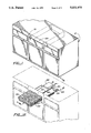
- FIG. 1 is a perspective view of a cabinet incorporating apparatus constructed in accordance with the teachings of the present invention, the apparatus being partially depicted by phantom lines;
- FIG. 1B is an enlarged, perspective, exploded view of the cutting board and support therefor;
- FIG. 2 is a cross-sectional, side view of the apparatus illustrating the cutting board in an extended position taken along line 2--2 in FIG. 1A;
- FIG. 2A is a view similar to FIG. 2 but illustrating the cutting board in a retracted position and disposed within the housing;
- FIG. 3 is a view taken along line 3--3 in FIG. 2;
- FIG. 4 is an enlarged side view illustrating details of the apparatus motor and motor mount taken along line 4--4 in FIG. 1A;
- FIG. 5 is a schematic presentation of circuitry employed in the apparatus to actuate and de-actuate the motor.
- apparatus constructed in accordance with the teachings of the present invention is designated by reference numeral 10, and such apparatus is illustrated as being installed in and employed in conjunction with a conventional cabinet 12.
- the apparatus 10 is in modular, self-contained form and may readily be installed in a cabinet.
- the housing 14 defines an interior 28 with the front wall 20 having an opening 30 formed therein which communicates with the interior.
- a cutting board 34 is movably mounted relative to housing 14 and movable between a first position, shown in FIG. 2A, wherein the cutting board is substantially disposed within the housing interior and a second position, shown in FIG. 2, wherein the cutting board projects outwardly from the housing through aperture 30.
- a support 44 supports the cutting board 34. As may best be seen with reference to FIG. 1B, the support 44 defines a storage compartment 46 which may be utilized to hold kitchen utensils 48 and the like.
- Support 44 includes support side walls 50, 52.
- Track elements 54 which may be of the type commonly found in association with cabinet drawers, are affixed to the outer surfaces of support side walls 50, 52. Track elements 54 are in slidable engagement with mating track elements 56 affixed to the inwardly disposed surfaces of the side walls 16, 18.
- the overall outer configuration of support 44 generally corresponds to that of cutting board 34 and, in the embodiment illustrated, cutting board 34 merely rests upon support 44 and is not fixedly attached thereto. Attachment means could be employed, however, without departing from the spirit or scope of the present invention.
- Threaded shaft 38 is positioned in a threaded receptacle 60 located in support rear wall 62. It will be appreciated that rotation of the threaded shaft by the motor will result in movement of the support and hence the cutting board. For example, and more particularly, rotation of the shaft in a clockwise direction will move the support and cutting board to the left as viewed in FIGS. 2, 2A, while rotation of the shaft in a counter clockwise direction will move the support and cutting board to the right as seen in those figures.
- the cutting board and support are normally located within the interior of the housing as shown in FIG. 2A. When, however, it is desired to use the cutting board or to have access to the storage compartment 46, the cutting board and support are located in their respective positions shown in FIG. 2.
- Actuation of the motor 36 may be accomplished through any suitable controller mechanism.
- the controller may be of the type employed in electric garage door openers. Such controller may be actuated by a remote control device or it may be actuated by a control button, such as button 64 located on the cabinet 12, hard wired thereto.
- a controller is designated by reference numeral 66. Controller 66 is programmed in customary fashion to provide a desired sequence of operations. The usual first step carried out in such sequence is to actuate the motor 36 to move the support and cutting board from the housing interior, i.e. from the position shown in FIG. 2A, to the extended position shown in FIG. 2. A limit switch 70 will be closed when the support and cutting board reach full extension thereby de-actuating the motor. Limit switch 70 may be disposed at any desired location. For example, limit switch 70 may be located adjacent to and operatively associated with the output shaft of motor 36 or it may be positioned at a location where it is engaged by the cutting board support during movement thereof.
- a torque switch device 68 is positioned closely adjacent to motor 36.
- Motor 36 has a bracket 72 projecting therefrom. Attached to the bracket is the lower end of a coil tension spring 74 which provides support for the motor at a location spaced from threaded shaft 38. At its upper end, spring 74 is connected to the end of an adjustment screw 76 which is threaded into a fitting extending through top wall panel 26. By turning the adjustment screw the height of the rear end of the motor can be adjusted.
- Switch device 68 includes a toggle 78 which passes through an opening in bracket 72.
- Movement of the bracket 72 relative to the toggle 78 will occur when there is a significant degree of movement of the motor at such location. This will occur when torque forces above a predetermined degree are applied to the motor. This occurs when the cutting board support and cutting board meet an obstruction. When outward movement of the support and cutting board is resisted to a predetermined degree, the motor output shaft will meet with additional resistance and the motor itself will move due to this increase in torque forces. This will actuate switch device 68. Controller 66 then automatically stops the motor and further movement of the cutting board and support. When an obstruction prevents inward movement of the board and support, torque will be applied to the motor in the opposite opposite direction. Actuation of the switch device resulting from this condition will cause the controller to reverse the motor and the board and support to move outwardly. This will prevent such occurrences as pinched fingers. If desired, the circuitry may incorporate a kill switch 80 to de-actuate the motor if limit switch 70 for any reason fails to de-actuate the motor during the retraction mode.
- a cover 82 covers aperture 30 when the cutting board and the support are fully retracted, that is, located within the housing interior 28.
- the cover designated by reference number 82, is attached to a coiled leaf spring 84 which normally retains the cover in the closed position illustrated in FIG. 2A.
- the support 44 and cutting board 34 move outwardly through opening 30 upon actuation of motor 36, the support engages the cover 82 and deflects it against the urging of spring 84 as shown. That is, movement of support 34 displaces the cover 82 from a closed position wherein the cover covers the housing opening to an open position wherein the housing opening is uncovered.
- the cover may, as shown, be pivotally attached to the outside of the cabinet adjacent to opening 30.
Landscapes
- Engineering & Computer Science (AREA)
- Food Science & Technology (AREA)
- Sawing (AREA)
Abstract
Apparatus including a housing defining an interior, a cutting board movable between a first position within the interior and a second position projecting outwardly from the housing, and transport means for selectively moving the cutting board between the first and second positions.
Description
This invention relates to a cutting board apparatus. More particularly, the invention relates to a combination of structural elements which provide for the transport of a cutting board from a first position wherein the cutting board is disposed in the interior of a housing and a second position wherein the cutting board projects from the housing. The apparatus particularly lends itself to installation in a cabinet and operation of the apparatus is carried out with virtually no manual exertion.
A search of the prior art located the following U.S. Pat. Nos.: 820,726, 4,041,964, 1,228,288, 3,770,262, and 4,765,603. These patents disclose cutting board or molding board installations of various types. In some cases, the boards are movably mounted with respect to a cabinet while in others the boards are essentially fixed in place. In any event, none of the patents discloses an arrangement providing for the motorized transport of a cutting board relative to a cabinet or the like.
The apparatus of the present invention includes a housing defining an interior and an opening communicating with the interior.
A cutting board is movably mounted relative to the housing and movable between a first position wherein the cutting board is substantially disposed within the housing interior and a second position wherein at least a portion of the cutting board projects outwardly from the housing through the aperture.
The apparatus additionally includes transport means for selectively moving the cutting board between the first and second positions. The transport means includes a motor and transmission means operatively associated with the motor and the cutting board to move the cutting board responsive to actuation of the motor.
Other features, advantages, and objects of the present invention will become apparent with reference to the following description and accompanying drawings.
FIG. 1 is a perspective view of a cabinet incorporating apparatus constructed in accordance with the teachings of the present invention, the apparatus being partially depicted by phantom lines;
FIG. 1A is a perspective view in a somewhat schematic format showing components of the apparatus in association with cabinet structure;
FIG. 1B is an enlarged, perspective, exploded view of the cutting board and support therefor;
FIG. 2 is a cross-sectional, side view of the apparatus illustrating the cutting board in an extended position taken along line 2--2 in FIG. 1A;
FIG. 2A is a view similar to FIG. 2 but illustrating the cutting board in a retracted position and disposed within the housing;
FIG. 3 is a view taken along line 3--3 in FIG. 2;
FIG. 4 is an enlarged side view illustrating details of the apparatus motor and motor mount taken along line 4--4 in FIG. 1A; and
FIG. 5 is a schematic presentation of circuitry employed in the apparatus to actuate and de-actuate the motor.
Referring now to the drawings, apparatus constructed in accordance with the teachings of the present invention is designated by reference numeral 10, and such apparatus is illustrated as being installed in and employed in conjunction with a conventional cabinet 12. The apparatus 10 is in modular, self-contained form and may readily be installed in a cabinet.
The apparatus 10 includes a housing 14 including spaced side walls 16, 18, a front wall 20, and a rear wall 22. The housing may also include top wall panels 24, 26 (FIGS. 2, 2A).
The housing 14 defines an interior 28 with the front wall 20 having an opening 30 formed therein which communicates with the interior.
A cutting board 34 is movably mounted relative to housing 14 and movable between a first position, shown in FIG. 2A, wherein the cutting board is substantially disposed within the housing interior and a second position, shown in FIG. 2, wherein the cutting board projects outwardly from the housing through aperture 30.
Transport means is provided for selectively moving the cutting board between the first and second positions. More particularly, the transport means includes a motor 36 and transmission means operatively associated with the motor and the cutting board to move the cutting board responsive to actuation of the motor. The transmission means includes a threaded shaft 38. One end of the shaft extends into a gear box 40. Gear box 40 may be of any suitable conventional construction and, in the usual fashion, such gear box translates rotational movement of the output shaft of the motor 36 into rotational movement of shaft 38. Motor 36 is of any suitable reversible electric motor construction.
A support 44 supports the cutting board 34. As may best be seen with reference to FIG. 1B, the support 44 defines a storage compartment 46 which may be utilized to hold kitchen utensils 48 and the like. Support 44 includes support side walls 50, 52. Track elements 54, which may be of the type commonly found in association with cabinet drawers, are affixed to the outer surfaces of support side walls 50, 52. Track elements 54 are in slidable engagement with mating track elements 56 affixed to the inwardly disposed surfaces of the side walls 16, 18. The overall outer configuration of support 44 generally corresponds to that of cutting board 34 and, in the embodiment illustrated, cutting board 34 merely rests upon support 44 and is not fixedly attached thereto. Attachment means could be employed, however, without departing from the spirit or scope of the present invention.
Threaded shaft 38 is positioned in a threaded receptacle 60 located in support rear wall 62. It will be appreciated that rotation of the threaded shaft by the motor will result in movement of the support and hence the cutting board. For example, and more particularly, rotation of the shaft in a clockwise direction will move the support and cutting board to the left as viewed in FIGS. 2, 2A, while rotation of the shaft in a counter clockwise direction will move the support and cutting board to the right as seen in those figures. The cutting board and support are normally located within the interior of the housing as shown in FIG. 2A. When, however, it is desired to use the cutting board or to have access to the storage compartment 46, the cutting board and support are located in their respective positions shown in FIG. 2.
Actuation of the motor 36 may be accomplished through any suitable controller mechanism. For example, the controller may be of the type employed in electric garage door openers. Such controller may be actuated by a remote control device or it may be actuated by a control button, such as button 64 located on the cabinet 12, hard wired thereto. In FIGS. 1A and 5, a controller is designated by reference numeral 66. Controller 66 is programmed in customary fashion to provide a desired sequence of operations. The usual first step carried out in such sequence is to actuate the motor 36 to move the support and cutting board from the housing interior, i.e. from the position shown in FIG. 2A, to the extended position shown in FIG. 2. A limit switch 70 will be closed when the support and cutting board reach full extension thereby de-actuating the motor. Limit switch 70 may be disposed at any desired location. For example, limit switch 70 may be located adjacent to and operatively associated with the output shaft of motor 36 or it may be positioned at a location where it is engaged by the cutting board support during movement thereof.
When it is desired to retract the support and cutting board, the operator again depresses the control button operatively associated with controller 66. This will cause the threaded shaft 38 to rotate in a counter clockwise direction thereby moving the support and cutting board to the right as viewed in FIGS. 2 and 2A until limit switch 70 is once again closed. Closure of the limit switch 70 will de-actuate the motor and the support and cutting board are retained within the interior of the housing in the respective positions illustrated in FIG. 2A. Alternatively, of course, two limit switches may be employed, one for de-actuating the motor when the cutting board support extends and the other when the cutting board retracts.
A torque switch device 68 is positioned closely adjacent to motor 36. Motor 36 has a bracket 72 projecting therefrom. Attached to the bracket is the lower end of a coil tension spring 74 which provides support for the motor at a location spaced from threaded shaft 38. At its upper end, spring 74 is connected to the end of an adjustment screw 76 which is threaded into a fitting extending through top wall panel 26. By turning the adjustment screw the height of the rear end of the motor can be adjusted. Switch device 68 includes a toggle 78 which passes through an opening in bracket 72.
Movement of the bracket 72 relative to the toggle 78 will occur when there is a significant degree of movement of the motor at such location. This will occur when torque forces above a predetermined degree are applied to the motor. This occurs when the cutting board support and cutting board meet an obstruction. When outward movement of the support and cutting board is resisted to a predetermined degree, the motor output shaft will meet with additional resistance and the motor itself will move due to this increase in torque forces. This will actuate switch device 68. Controller 66 then automatically stops the motor and further movement of the cutting board and support. When an obstruction prevents inward movement of the board and support, torque will be applied to the motor in the opposite opposite direction. Actuation of the switch device resulting from this condition will cause the controller to reverse the motor and the board and support to move outwardly. This will prevent such occurrences as pinched fingers. If desired, the circuitry may incorporate a kill switch 80 to de-actuate the motor if limit switch 70 for any reason fails to de-actuate the motor during the retraction mode.
It is to be noted that a cover 82 covers aperture 30 when the cutting board and the support are fully retracted, that is, located within the housing interior 28. The cover, designated by reference number 82, is attached to a coiled leaf spring 84 which normally retains the cover in the closed position illustrated in FIG. 2A. When, however, the support 44 and cutting board 34 move outwardly through opening 30 upon actuation of motor 36, the support engages the cover 82 and deflects it against the urging of spring 84 as shown. That is, movement of support 34 displaces the cover 82 from a closed position wherein the cover covers the housing opening to an open position wherein the housing opening is uncovered. The cover may, as shown, be pivotally attached to the outside of the cabinet adjacent to opening 30.
Claims (8)
1. Modular, self-contained cutting board apparatus for installation in a cabinet, said apparatus comprising, in combination:
a housing defining an interior and an opening communicating with said interior, said housing positionable in said cabinet with said opening in communication with the exterior of said cabinet;
a cutting board having a horizontally disposed, substantially flat cutting surface movably mounted relative to said housing and movable between a first position wherein said cutting board is substantially disposed within said housing interior and a second position wherein at least a portion of said cutting board projects outwardly from said housing externally of said cabinet through said aperture with said cutting surface exposed for access by a user; and
transport means for selectively moving said cutting board between said first and second positions along a predetermined horizontal path of movement, said transport means including a cutting board support for supporting said cutting board, a motor, and transmission means operatively associated with said motor and said cutting board support to move said cutting board end-wise along said predetermined horizontal path of movement responsive to actuation of said motor, said cutting board support being connected to said transmission means, said transmission means including a threaded shaft rotatable by said motor, and said cutting board support defining a receptacle threadedly engaged with said shaft, rotation of said shaft relative to said receptacle imparting movement to said cutting board support and cutting board between said first and second positions, the cutting board cutting surface being disposed above said cutting board support whereby access to said cutting surface by a user is unimpaired by said cutting board support when said cutting board portion projects outwardly from said housing externally of said cabinet.
2. The apparatus according to claim 1 additionally comprising a cover movably mounted relative to said housing externally of said cabinet and movable between a closed position wherein said cover covers said housing opening and an open position wherein said housing opening is uncovered and spring biasing means operatively connected with said cover and said housing continuously urging said cover to said closed position.
3. The apparatus according to claim 2 wherein said cover is engageable by either said cutting board or said cutting board support during movement of said cutting board from said first position to said second position to move said cover from said closed position to said open position against the bias exerted by said spring biasing means.
4. The apparatus according to claim 1 including means for interrupting movement of said cutting board as said cutting board moves between said first position and said second position responsive to said cutting board engaging an obstruction.
5. The apparatus according to claim 4 wherein said means for interrupting movement of said cutting board includes means for sensing when a predetermined magnitude of torque is applied to said motor.
6. The apparatus according to claim 5 wherein said torque sensing means comprises torque switch means located adjacent to said motor, said motor being mounted for movement relative to said torque switch means and engageable with said torque switch means when the torque applied to said motor exceeds said predetermined magnitude.
7. The apparatus according to claim 1 additionally comprising limit switch means for de-actuating said motor after said cutting board has moved between said first and second positions.
8. The apparatus according to claim 1 wherein the support defines a storage compartment and wherein the cutting board is positioned over said storage compartment and selectively manually removable from the support to expose said storage compartment.
Priority Applications (1)
| Application Number | Priority Date | Filing Date | Title |
|---|---|---|---|
| US07/545,204 US5031975A (en) | 1990-06-28 | 1990-06-28 | Cutting board apparatus |
Applications Claiming Priority (1)
| Application Number | Priority Date | Filing Date | Title |
|---|---|---|---|
| US07/545,204 US5031975A (en) | 1990-06-28 | 1990-06-28 | Cutting board apparatus |
Publications (1)
| Publication Number | Publication Date |
|---|---|
| US5031975A true US5031975A (en) | 1991-07-16 |
Family
ID=24175273
Family Applications (1)
| Application Number | Title | Priority Date | Filing Date |
|---|---|---|---|
| US07/545,204 Expired - Lifetime US5031975A (en) | 1990-06-28 | 1990-06-28 | Cutting board apparatus |
Country Status (1)
| Country | Link |
|---|---|
| US (1) | US5031975A (en) |
Cited By (30)
| Publication number | Priority date | Publication date | Assignee | Title |
|---|---|---|---|---|
| US5215363A (en) * | 1992-01-27 | 1993-06-01 | Warwick Iii William C | Trash collection apparatus |
| US5524859A (en) * | 1994-02-08 | 1996-06-11 | Squires; Carlton G. | Security mounting for audio equipment in a motor vehicle |
| GB2311088A (en) * | 1996-03-11 | 1997-09-17 | Richard Mark Morrish | Power driven step plinth for shelves and cupboards |
| US5848772A (en) * | 1996-01-02 | 1998-12-15 | Fitzgerald; Theodore L. | Kitchen cutting board storage apparatus |
| US5882095A (en) * | 1998-03-26 | 1999-03-16 | Green; Donald E. | Portable prayer altar |
| USD427821S (en) * | 1999-08-13 | 2000-07-11 | Whistance-Smith Wallace J | Multi-functional work surface for a seating unit |
| US6220560B1 (en) * | 1997-06-04 | 2001-04-24 | Lawrence Charles Bugeja | Plate holder |
| US20030049410A1 (en) * | 2001-09-07 | 2003-03-13 | Munagavalasa Murthy S. | Film material and method of dispensing a volatile substance |
| US20030049294A1 (en) * | 2001-09-07 | 2003-03-13 | Jose Porchia | Film material |
| US20030047044A1 (en) * | 2001-09-07 | 2003-03-13 | Jose Porchia | Processing method using a film material |
| US20030049394A1 (en) * | 2001-09-07 | 2003-03-13 | Jose Porchia | Film material |
| US6793300B1 (en) | 2002-10-21 | 2004-09-21 | Donald Frank Gillette | Cabinet storage for cutting board and method |
| US20050006998A1 (en) * | 2003-05-20 | 2005-01-13 | Bsh Bosch Und Siemens Hausgerate Gmbh | Refrigerator with extendable supports |
| US6846449B2 (en) | 2001-09-07 | 2005-01-25 | S. C. Johnson Home Storage, Inc. | Method of producing an electrically charged film |
| US20060021373A1 (en) * | 2004-07-29 | 2006-02-02 | Lg Electronics Inc. | Bottom drawer type refrigerator having basket lift device |
| US20070068428A1 (en) * | 2005-09-28 | 2007-03-29 | Haur Luen Enterprise Co., Ltd. | Desk with retractable board and retractable board device |
| US20080302016A1 (en) * | 2005-11-29 | 2008-12-11 | Amos Halfon | System For Positioning Sliding Doors |
| US20090322004A1 (en) * | 2008-06-24 | 2009-12-31 | Keith Young | Apparatus for treating food substances |
| US20110156564A1 (en) * | 2008-06-24 | 2011-06-30 | Aktiebolaget Electrolux | Space efficient multi-function kitchen appliance |
| US20120145663A1 (en) * | 2010-12-13 | 2012-06-14 | Proper Storage Systems, LLC | Roll-out shelving storage rack system |
| US20120235550A1 (en) * | 2011-03-17 | 2012-09-20 | Mckesson Automation Inc. | Drawer assembly and associated method for controllably limiting the slideable extension of a drawer |
| JP2013102957A (en) * | 2011-11-14 | 2013-05-30 | Toto Ltd | System kitchen |
| USD699083S1 (en) * | 2012-02-16 | 2014-02-11 | Hasegawa Corporation | Cutting board plane |
| US20140042685A1 (en) * | 2012-08-09 | 2014-02-13 | Christopher Andrew Nordstrom | Culinary device |
| USD699524S1 (en) * | 2012-07-05 | 2014-02-18 | Hasegawa Corporation | Cutting board scraper |
| US9066626B2 (en) | 2012-02-07 | 2015-06-30 | Keith Young | Cutting board apparatus with collapsible tray |
| US9883741B2 (en) * | 2016-05-02 | 2018-02-06 | Vincent Demasi, III | Foldable step system |
| US20180259246A1 (en) * | 2017-03-10 | 2018-09-13 | Samsung Electronics Co., Ltd. | Lifting apparatus and refrigerator having the same |
| US10492598B2 (en) * | 2018-04-18 | 2019-12-03 | Hadida Worldwide Company, Llc. | Motorized extendable table |
| US20240060706A1 (en) * | 2022-08-17 | 2024-02-22 | Matthew DAVENPORT | Pop-Up Food Preparation Counter Cabinet and Refrigerator |
Citations (10)
| Publication number | Priority date | Publication date | Assignee | Title |
|---|---|---|---|---|
| US820726A (en) * | 1905-08-07 | 1906-05-15 | James S Mcquinn | Molding-board. |
| US1228288A (en) * | 1915-10-20 | 1917-05-29 | Robert L Bower | Folding dough-board and biscuit-cutter. |
| US2372718A (en) * | 1943-11-29 | 1945-04-03 | Seng Co | Desk with typewriter carrier |
| US2722179A (en) * | 1953-12-28 | 1955-11-01 | Herring Hall Marvin Safe Compa | Bank teller's drive-in window unit |
| US3770262A (en) * | 1972-02-14 | 1973-11-06 | G Bailey | Kitchen cutting board |
| US4041964A (en) * | 1976-06-21 | 1977-08-16 | Ellis Shamoon | Kitchen cuttingboard |
| US4151804A (en) * | 1977-10-31 | 1979-05-01 | Eberhard Kunze | Elevating apparatus particularly adapted for television receiver support-tables and the like |
| US4437711A (en) * | 1982-05-28 | 1984-03-20 | Spacesaver Corporation | Movable storage unit controls |
| US4765603A (en) * | 1986-04-14 | 1988-08-23 | Raymond Huppert | Cutting board |
| US4834470A (en) * | 1987-09-08 | 1989-05-30 | Carter-Hoffmann Corporation | Food service cabinet with self-closing door |
-
1990
- 1990-06-28 US US07/545,204 patent/US5031975A/en not_active Expired - Lifetime
Patent Citations (10)
| Publication number | Priority date | Publication date | Assignee | Title |
|---|---|---|---|---|
| US820726A (en) * | 1905-08-07 | 1906-05-15 | James S Mcquinn | Molding-board. |
| US1228288A (en) * | 1915-10-20 | 1917-05-29 | Robert L Bower | Folding dough-board and biscuit-cutter. |
| US2372718A (en) * | 1943-11-29 | 1945-04-03 | Seng Co | Desk with typewriter carrier |
| US2722179A (en) * | 1953-12-28 | 1955-11-01 | Herring Hall Marvin Safe Compa | Bank teller's drive-in window unit |
| US3770262A (en) * | 1972-02-14 | 1973-11-06 | G Bailey | Kitchen cutting board |
| US4041964A (en) * | 1976-06-21 | 1977-08-16 | Ellis Shamoon | Kitchen cuttingboard |
| US4151804A (en) * | 1977-10-31 | 1979-05-01 | Eberhard Kunze | Elevating apparatus particularly adapted for television receiver support-tables and the like |
| US4437711A (en) * | 1982-05-28 | 1984-03-20 | Spacesaver Corporation | Movable storage unit controls |
| US4765603A (en) * | 1986-04-14 | 1988-08-23 | Raymond Huppert | Cutting board |
| US4834470A (en) * | 1987-09-08 | 1989-05-30 | Carter-Hoffmann Corporation | Food service cabinet with self-closing door |
Cited By (40)
| Publication number | Priority date | Publication date | Assignee | Title |
|---|---|---|---|---|
| US5215363A (en) * | 1992-01-27 | 1993-06-01 | Warwick Iii William C | Trash collection apparatus |
| US5524859A (en) * | 1994-02-08 | 1996-06-11 | Squires; Carlton G. | Security mounting for audio equipment in a motor vehicle |
| US5848772A (en) * | 1996-01-02 | 1998-12-15 | Fitzgerald; Theodore L. | Kitchen cutting board storage apparatus |
| GB2311088A (en) * | 1996-03-11 | 1997-09-17 | Richard Mark Morrish | Power driven step plinth for shelves and cupboards |
| US6220560B1 (en) * | 1997-06-04 | 2001-04-24 | Lawrence Charles Bugeja | Plate holder |
| US5882095A (en) * | 1998-03-26 | 1999-03-16 | Green; Donald E. | Portable prayer altar |
| USD427821S (en) * | 1999-08-13 | 2000-07-11 | Whistance-Smith Wallace J | Multi-functional work surface for a seating unit |
| US20030049394A1 (en) * | 2001-09-07 | 2003-03-13 | Jose Porchia | Film material |
| US6846449B2 (en) | 2001-09-07 | 2005-01-25 | S. C. Johnson Home Storage, Inc. | Method of producing an electrically charged film |
| US20030047044A1 (en) * | 2001-09-07 | 2003-03-13 | Jose Porchia | Processing method using a film material |
| US20030049410A1 (en) * | 2001-09-07 | 2003-03-13 | Munagavalasa Murthy S. | Film material and method of dispensing a volatile substance |
| US20030049294A1 (en) * | 2001-09-07 | 2003-03-13 | Jose Porchia | Film material |
| US6899931B2 (en) | 2001-09-07 | 2005-05-31 | S. C. Johnson Home Storage, Inc. | Film material |
| US6793300B1 (en) | 2002-10-21 | 2004-09-21 | Donald Frank Gillette | Cabinet storage for cutting board and method |
| US20050006998A1 (en) * | 2003-05-20 | 2005-01-13 | Bsh Bosch Und Siemens Hausgerate Gmbh | Refrigerator with extendable supports |
| US20060021373A1 (en) * | 2004-07-29 | 2006-02-02 | Lg Electronics Inc. | Bottom drawer type refrigerator having basket lift device |
| US20070068428A1 (en) * | 2005-09-28 | 2007-03-29 | Haur Luen Enterprise Co., Ltd. | Desk with retractable board and retractable board device |
| US20080302016A1 (en) * | 2005-11-29 | 2008-12-11 | Amos Halfon | System For Positioning Sliding Doors |
| CN101523006A (en) * | 2005-11-29 | 2009-09-02 | 阿方·爱莫斯 | sliding door positioning system |
| EP1954905A4 (en) * | 2005-11-29 | 2013-08-21 | Hardoor Mechanism Production Ltd | POSITIONING SYSTEM FOR SLIDING DOORS |
| US8096629B2 (en) * | 2005-11-29 | 2012-01-17 | Hardoor Mechanism Productions Ltd. | System for positioning sliding doors |
| US20110156564A1 (en) * | 2008-06-24 | 2011-06-30 | Aktiebolaget Electrolux | Space efficient multi-function kitchen appliance |
| US8251357B2 (en) | 2008-06-24 | 2012-08-28 | Keith Young | Apparatus for treating food substances |
| US9049963B2 (en) | 2008-06-24 | 2015-06-09 | Keith Young | Apparatus for treating food substances |
| US20090322004A1 (en) * | 2008-06-24 | 2009-12-31 | Keith Young | Apparatus for treating food substances |
| US20120145663A1 (en) * | 2010-12-13 | 2012-06-14 | Proper Storage Systems, LLC | Roll-out shelving storage rack system |
| US8851300B2 (en) * | 2010-12-13 | 2014-10-07 | Proper Storage Systems, LLC | Roll-out shelving storage rack system |
| US8662606B2 (en) * | 2011-03-17 | 2014-03-04 | Mckesson Automation Inc. | Drawer assembly and associated method for controllably limiting the slideable extension of a drawer |
| US20120235550A1 (en) * | 2011-03-17 | 2012-09-20 | Mckesson Automation Inc. | Drawer assembly and associated method for controllably limiting the slideable extension of a drawer |
| JP2013102957A (en) * | 2011-11-14 | 2013-05-30 | Toto Ltd | System kitchen |
| US9066626B2 (en) | 2012-02-07 | 2015-06-30 | Keith Young | Cutting board apparatus with collapsible tray |
| USD699083S1 (en) * | 2012-02-16 | 2014-02-11 | Hasegawa Corporation | Cutting board plane |
| USD699524S1 (en) * | 2012-07-05 | 2014-02-18 | Hasegawa Corporation | Cutting board scraper |
| US20140042685A1 (en) * | 2012-08-09 | 2014-02-13 | Christopher Andrew Nordstrom | Culinary device |
| US9565974B2 (en) * | 2012-08-09 | 2017-02-14 | Christopher Andrew Nordstrom | Culinary device |
| US9883741B2 (en) * | 2016-05-02 | 2018-02-06 | Vincent Demasi, III | Foldable step system |
| US20180259246A1 (en) * | 2017-03-10 | 2018-09-13 | Samsung Electronics Co., Ltd. | Lifting apparatus and refrigerator having the same |
| US10598425B2 (en) * | 2017-03-10 | 2020-03-24 | Samsung Electronics Co., Ltd. | Lifting apparatus and refrigerator having the same |
| US10492598B2 (en) * | 2018-04-18 | 2019-12-03 | Hadida Worldwide Company, Llc. | Motorized extendable table |
| US20240060706A1 (en) * | 2022-08-17 | 2024-02-22 | Matthew DAVENPORT | Pop-Up Food Preparation Counter Cabinet and Refrigerator |
Similar Documents
| Publication | Publication Date | Title |
|---|---|---|
| US5031975A (en) | Cutting board apparatus | |
| US5769710A (en) | Discharge outlet opening and closing apparatus of air conditioner | |
| US4541202A (en) | Sliding door operator and lock | |
| US5355624A (en) | Modular, powered closure apparatus | |
| US4628636A (en) | Garage door operator mechanism | |
| US20210022496A1 (en) | Motorized basket lifting mechanism | |
| US3984136A (en) | Lock for sliding doors | |
| US5770935A (en) | Door opening system and receptacle | |
| US5524979A (en) | Overhead storage mechanism | |
| US6782661B2 (en) | Mechanical actuator for a multi-position window | |
| US4128120A (en) | Tambour door and housing assembly | |
| US3059840A (en) | Deal drawer construction for bank drive-up window | |
| US5341241A (en) | Trap door for projection screen case | |
| US4496811A (en) | Foot switch safety enclosure | |
| US4337972A (en) | Panel board safety latch assembly | |
| CA2071329A1 (en) | Adjustable Door Balancing Mechanism | |
| CA2312314A1 (en) | Self-rising door handle | |
| US3707260A (en) | Mail box with remote signal transmitter | |
| US4149222A (en) | Bed light safety apparatus | |
| EP2441351B1 (en) | Visible device for the assembly of a wall cupboard, with side regulation | |
| US5186230A (en) | Mechanism for operating bi-fold doors | |
| US2820112A (en) | Retractable cord mechanism | |
| US12419413B2 (en) | Accessibility of storage cabinets | |
| US5755496A (en) | Cabinet for displaying objects | |
| US20020195828A1 (en) | Closure device |
Legal Events
| Date | Code | Title | Description |
|---|---|---|---|
| STCF | Information on status: patent grant |
Free format text: PATENTED CASE |
|
| FPAY | Fee payment |
Year of fee payment: 4 |
|
| REMI | Maintenance fee reminder mailed | ||
| FPAY | Fee payment |
Year of fee payment: 8 |
|
| SULP | Surcharge for late payment | ||
| FPAY | Fee payment |
Year of fee payment: 12 |