US5025987A - Rail securement apparatus - Google Patents
Rail securement apparatus Download PDFInfo
- Publication number
- US5025987A US5025987A US07/390,555 US39055589A US5025987A US 5025987 A US5025987 A US 5025987A US 39055589 A US39055589 A US 39055589A US 5025987 A US5025987 A US 5025987A
- Authority
- US
- United States
- Prior art keywords
- rail
- base
- anchor
- foundation
- nose
- Prior art date
- Legal status (The legal status is an assumption and is not a legal conclusion. Google has not performed a legal analysis and makes no representation as to the accuracy of the status listed.)
- Expired - Fee Related
Links
Images
Classifications
-
- E—FIXED CONSTRUCTIONS
- E01—CONSTRUCTION OF ROADS, RAILWAYS, OR BRIDGES
- E01B—PERMANENT WAY; PERMANENT-WAY TOOLS; MACHINES FOR MAKING RAILWAYS OF ALL KINDS
- E01B9/00—Fastening rails on sleepers, or the like
- E01B9/02—Fastening rails, tie-plates, or chairs directly on sleepers or foundations; Means therefor
- E01B9/28—Fastening on wooden or concrete sleepers or on masonry with clamp members
Definitions
- This invention relates to an apparatus for securing a rail to a foundation and, in particular, to a rail securement clip utilizing rubber pad means engageable with the rail to absorb rail movement energy and secure the rail in place.
- a common type of anchor includes a threaded stud fastened to the foundation perpendicular to its surface and near the foot of the rail.
- a steel clip fits on the anchor against the foundation and overlaps the foot of the rail.
- a washer is placed over the stud and against the clip and a nut is threaded on the stud against the washer and clip to sandwich the rail foot between the clip and the foundation.
- a hole may be threaded in the foundation and a bolt may be inserted through the clip and threaded into the hole to fasten the clip against the rail and secure the rail to the foundation.
- a well known clip design comprises a rectangular block of steel having a length in a direction laterally of the length of the rail that is somewhat longer than a width parallel to the length of the rail.
- the clip has a slot-shaped through opening that is centered in the long direction of the clip, i.e. in a direction laterally of the rail length.
- a portion of the bottom of the clip is tapered to accommodate the upward slant of the rail foot.
- Most rail systems for industrial equipment being currently installed utilize 60 pound per yard rail stock.
- the clips typically used in these systems have slotted openings that allow the anchor stud to be placed almost directly against the edge of the foot of the rail.
- rubber nosed rail clips require a minimum spacing between the anchor stud or bolt and the foot of the rail ranging approximately from 1/2" to 1".
- rubber nosed rail clips often have a greater height than the relatively standard type older steel clips due to the addition of the rubber material in the nose of the clip.
- the additional height and the increased spacing between the anchor and the foot of the rail required by rubber nosed rail clips presents particularly difficult problems when rail installations are being renovated and it is desired to convert the rail securement devices from the older steel clips to a rubber nosed type clip.
- These problems include the removal and replacement of the anchors at a greater distance from the foot of the rail, and the installation of longer anchors to fasten greater height clips and also to accommodate increased rail height due to the addition of a rubber pad beneath the rail.
- increasing the anchor and clip heights may obstruct the moving of the equipment wheels on the rails so that rubber nosed clips cannot actually be used.
- the applicants' invention is an improvement over presently known rail securement clips having the drawbacks described above.
- the invention is carried out by providing an apparatus including a base having an opening therethrough for receiving an anchor projecting from a foundation, a nose extending laterally of the base from the upper portion of the base and overlying the foot of the rail, and a pair of spaced apart fingers affixed to the nose and to an upper portion of the base.
- the through opening in the base has an orifice positioned in the space between the fingers.
- the base and fingers form a recess into which the anchor projects and securement means may be fastened to the anchor and positioned within the recess to hold the apparatus against the rail and thereby secure the rail to the foundation.
- the nose may include a rubber pad means engaging the foot of the rail to provide an energy absorbing securement of the rail.
- the through opening in the base may have an open side facing in the direction of the lateral extension of the nose from the base so that the anchor projecting through the opening may be positioned adjacent to or in engagement with the foot of the rail.
- the nose has a side facing the securement means which is spaced laterally from the base.
- the rubber pad means may comprise two spaced apart portions with the nose side facing the securement means between the rubber pad portions. The rubber pad means will thereby not interfere with the attachment of the securement means to the anchor or the positioning of the anchor against the rail foot.
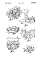
- FIG. 1 is a perspective view of the rail securement apparatus according to the invention
- FIG. 2 is a side elevation view of the apparatus shown in FIG. 1 illustrating the apparatus securing a rail in position on a foundation
- FIG. 3 is an end elevation view of the apparatus shown in FIG. 1 attached to an anchor projecting from a foundation
- FIG. 4 is a plan view of the apparatus shown in FIG. 1
- FIG. 5 is a plan view of an alternate embodiment of the invention
- FIG. 6 is a side elevation view of the apparatus shown in FIG. 5.
- the rail securement apparatus includes a base 2 having an upper portion 10, a nose 4 having rubber pads 12 and 14, and spaced apart fingers 6 and 8 affixed to the nose 4 and to the upper portion 10 of the base.
- a rail 16 has a head 18, a flange 20 and a foot 22 for supporting equipment traveling on the rail.
- the rail rests on a rubber rail pad 24 and has a length in the direction of the center line 28 shown in FIG. 4.
- the foot 22 has a height above the foundation 26 identified by the letter a as shown in FIG. 2.
- An anchor stud 30 projects from the foundation 26 and a securement means 32 is attached to the anchor stud 30 against the surface 11 of the upper portion 10 of the base which is not greater than the height a of the foot 22, as shown in FIG. 2 2.
- the nose 4 of the rail securement apparatus over the foot 22 of the rail is such that when the securement means 32 is attached to the anchor 30 and against the base 2, the rail is secured to the foundation. It may be noted however, that the rail may in some cases be preferably secured to the foundation with the nose 4 overlying but not engaging the rail foot 22 so that the latter is merely restricted in its movement.
- the base 2 includes a through opening 34 having an orifice 36 in the upper portion 10 of the base.
- the opening 34 has an open side 38 in the lateral direction of the base transverse to the length of the rail 16 and toward the rail foot 22.
- the base 2 further includes lateral sides 40 and 42 between which the open side 38 is positioned and which may be located in engagement with the rail foot 22 if desired for purposes of securing the rail 16 to the foundation 26.
- the securement apparatus includes a recess 44 between and straddled by the fingers 6 and 8 in t which the orifice 36 of the opening 34 opens and which is formed by the upper portion 10 of the base 2, the fingers 6 and 8, and the nose 4.
- the recess has a wall 46 which comprises walls 48 and 50 respectively of fingers 6 and 8 and wall portion 52 of nose 4.
- the wall portion 52 of nose 4 comprising a part of the recess 44, is positioned in a lateral direction from the base 2 and the open side 38 toward the rail foot 22.
- the opening 34 may be slot shaped with a length in the lateral direction of the base 2 so that the rail securement apparatus may be adjustable in its engagement position with the rail foot 22 and on the anchor 30.
- the rubber pads 12 and 14 are spaced apart on the nose 4 so that they also do not interfere with the projection of the anchor 30 through the base 2 or the attachment of the securement means 32 to the anchor 30.
- the wall portion 52 of the nose 4 because of the spacing apart of the rubber pads 12 and 14, may be disposed in the space between the rubber pads 12 and 14 to provide the recess area required for attachment of the securement means 32 to the anchor 30 when the anchor 30 is adjacent to or extending out of the open side 38 and the securement means 32 is adjacent the wall portion 52 of the nose 4.
- the base 2 itself may have a minimal height which in turn minimizes the height of the overall rail securement apparatus.
- the integrity of the rail clip is attained by also affixing the fingers 6 and 8 to the upper portion 10 of the base 2.
- the strength of the rail clip is enhanced if the fingers 6 and 8 are affixed to the upper portion of the base 2 along the full lateral width of the base 2, as shown in FIGS. 1-4.
- the height of the nose 4 and the fingers 6 and 8, and thereby the height of the recess 44,. is such that the recess height will not exceed the typical height of the anchor 30 above the base 2 projecting from the foundation 26.
- the rail securement apparatus will not exceed the height of the original anchors 30 from the foundation 26 and thereby interfere with the rail wheels of the equipment supported by the rail 16.
- a common type of anchor stud is the threaded anchor 30 illustrated in FIGS. 2 and 3, however, a threaded receptacle in the foundation into which a threaded bolt is inserted can also be utilized.
- a typical securement means 32 includes a threaded nut 54 and washer 56.
- the washer 56 is positioned over the anchor stud 30 against the surface 11 of the upper portion 10 of the base 2 and the nut 54 is threaded on the stud 30 against the washer to attach the securement apparatus to the anchor 30 and position the securement apparatus relative to the rail foot 22 and secure the rail 16 to the foundation.
- the rubber pads 12 and 14 overlie and engage the rail foot 22 in a resilient manner which results in the absorption of dynamic energy of the rail 16 and minimizes transfer of this energy to the anchor 30.
- the rubber nose pads 12 and 14 may also be sized such that they overlie but do not always engage the foot 22, but are engaged by the foot 22 only as the result of movement of the rail 16 and foot 22.
- the base 2 has an upper portion 10 having a through opening 60 including an orifice 62 opening in to a recess 64.
- the opening 60 includes a side 58 spaced from a lateral side 66 of the base 2 facing the rail foot 22.
- a pair of fingers 68 and 70, spaced apart in the lengthwise direction of the rail 16, are affixed to and extend from the upper portion 10 of the base 2.
- the finger 68 has a nose member 72 on which is mounted a rubber nose pad 74 and the finger 70 has a nose member 76 on which is mounted a rubber nose pad 78.
- FIGS. 5 and 6 could be modified to include laterally open side adjacent rail foot 22 of the through opening 60 to permit engagement of the anchor 30 with the rail foot 22, if desired.
- the embodiment of FIGS. 1-4 could be modified to utilize the opening 60 shown in FIGS. 5 and 6 that does not include the lateral side opening toward the base 2. Neither of such modifications to the rail clip of the invention would depart from its spirit and scope.
Landscapes
- Engineering & Computer Science (AREA)
- Mechanical Engineering (AREA)
- Architecture (AREA)
- Civil Engineering (AREA)
- Structural Engineering (AREA)
- Vibration Prevention Devices (AREA)
- Buildings Adapted To Withstand Abnormal External Influences (AREA)
- Railway Tracks (AREA)
- Machines For Laying And Maintaining Railways (AREA)
Abstract
Description
Claims (11)
Priority Applications (3)
| Application Number | Priority Date | Filing Date | Title |
|---|---|---|---|
| US07/390,555 US5025987A (en) | 1989-08-07 | 1989-08-07 | Rail securement apparatus |
| CA002019948A CA2019948C (en) | 1989-08-07 | 1990-06-27 | Rail securement apparatus |
| MX021880A MX171190B (en) | 1989-08-07 | 1990-08-07 | RAIL FIXING DEVICE |
Applications Claiming Priority (1)
| Application Number | Priority Date | Filing Date | Title |
|---|---|---|---|
| US07/390,555 US5025987A (en) | 1989-08-07 | 1989-08-07 | Rail securement apparatus |
Publications (1)
| Publication Number | Publication Date |
|---|---|
| US5025987A true US5025987A (en) | 1991-06-25 |
Family
ID=23542946
Family Applications (1)
| Application Number | Title | Priority Date | Filing Date |
|---|---|---|---|
| US07/390,555 Expired - Fee Related US5025987A (en) | 1989-08-07 | 1989-08-07 | Rail securement apparatus |
Country Status (3)
| Country | Link |
|---|---|
| US (1) | US5025987A (en) |
| CA (1) | CA2019948C (en) |
| MX (1) | MX171190B (en) |
Cited By (10)
| Publication number | Priority date | Publication date | Assignee | Title |
|---|---|---|---|---|
| US20020182003A1 (en) * | 2001-04-12 | 2002-12-05 | Hans-Herlof Hardtke | Clamping device for clamping girders |
| US20110047786A1 (en) * | 2009-02-11 | 2011-03-03 | Vossloh-Werke Gmbh | Guide plate for a system for securing a rail on a substrate and a system comprising such guide plate |
| US8763922B2 (en) * | 2011-05-13 | 2014-07-01 | Vinylast, Inc. | Method and apparatus for installing a railing system |
| US20150117945A1 (en) * | 2013-10-25 | 2015-04-30 | The Boeing Company | Clamp device for use with a decompression panel in an aircraft assembly |
| US9440744B2 (en) | 2013-10-17 | 2016-09-13 | The Boeing Company | Decompression panel assembly and method of equalizing air pressure differential |
| US9499251B2 (en) | 2013-10-25 | 2016-11-22 | The Boeing Company | Decompression panel for use in an aircraft |
| USD817851S1 (en) | 2014-03-28 | 2018-05-15 | The Boeing Company | Decompression panel |
| US20190054584A1 (en) * | 2017-08-16 | 2019-02-21 | Michael W Stark | Vise Clamp |
| CN109850757A (en) * | 2019-01-22 | 2019-06-07 | 天津市管道工程集团有限公司 | Easy-to-mount overhead traveling crane guide rail |
| US11759901B2 (en) * | 2021-07-07 | 2023-09-19 | Pero Ivicevic | Clamp for retaining a workpiece |
Citations (3)
| Publication number | Priority date | Publication date | Assignee | Title |
|---|---|---|---|---|
| US497679A (en) * | 1893-05-16 | Beam-clamp for pipe-hangers | ||
| GB1122255A (en) * | 1965-06-22 | 1968-08-07 | Ressords Du Nord S A | Improvements in or relating to an elastically yieldable rail fastener |
| US3934800A (en) * | 1973-04-17 | 1976-01-27 | Molyneux Rail Clips Limited | Track rail anchorages |
-
1989
- 1989-08-07 US US07/390,555 patent/US5025987A/en not_active Expired - Fee Related
-
1990
- 1990-06-27 CA CA002019948A patent/CA2019948C/en not_active Expired - Fee Related
- 1990-08-07 MX MX021880A patent/MX171190B/en unknown
Patent Citations (3)
| Publication number | Priority date | Publication date | Assignee | Title |
|---|---|---|---|---|
| US497679A (en) * | 1893-05-16 | Beam-clamp for pipe-hangers | ||
| GB1122255A (en) * | 1965-06-22 | 1968-08-07 | Ressords Du Nord S A | Improvements in or relating to an elastically yieldable rail fastener |
| US3934800A (en) * | 1973-04-17 | 1976-01-27 | Molyneux Rail Clips Limited | Track rail anchorages |
Cited By (16)
| Publication number | Priority date | Publication date | Assignee | Title |
|---|---|---|---|---|
| EP1249621A3 (en) * | 2001-04-12 | 2003-05-28 | Lisega Gmbh | Device for clamping supports |
| US7021855B2 (en) | 2001-04-12 | 2006-04-04 | Lisega Gmbh | Clamping device for clamping girders |
| US20020182003A1 (en) * | 2001-04-12 | 2002-12-05 | Hans-Herlof Hardtke | Clamping device for clamping girders |
| US20110047786A1 (en) * | 2009-02-11 | 2011-03-03 | Vossloh-Werke Gmbh | Guide plate for a system for securing a rail on a substrate and a system comprising such guide plate |
| US8763922B2 (en) * | 2011-05-13 | 2014-07-01 | Vinylast, Inc. | Method and apparatus for installing a railing system |
| US9440744B2 (en) | 2013-10-17 | 2016-09-13 | The Boeing Company | Decompression panel assembly and method of equalizing air pressure differential |
| US9751609B2 (en) | 2013-10-25 | 2017-09-05 | The Boeing Company | Decompression panel for use in an aircraft |
| US9499251B2 (en) | 2013-10-25 | 2016-11-22 | The Boeing Company | Decompression panel for use in an aircraft |
| US20150117945A1 (en) * | 2013-10-25 | 2015-04-30 | The Boeing Company | Clamp device for use with a decompression panel in an aircraft assembly |
| US10071795B2 (en) * | 2013-10-25 | 2018-09-11 | The Boeing Company | Clamp device for use with a decompression panel in an aircraft assembly |
| USD817851S1 (en) | 2014-03-28 | 2018-05-15 | The Boeing Company | Decompression panel |
| US20190054584A1 (en) * | 2017-08-16 | 2019-02-21 | Michael W Stark | Vise Clamp |
| US10857638B2 (en) * | 2017-08-16 | 2020-12-08 | Michael W Stark | Vise clamp |
| CN109850757A (en) * | 2019-01-22 | 2019-06-07 | 天津市管道工程集团有限公司 | Easy-to-mount overhead traveling crane guide rail |
| CN109850757B (en) * | 2019-01-22 | 2024-04-12 | 天津市管道工程集团有限公司 | Crown block guide rail convenient to disassemble and assemble |
| US11759901B2 (en) * | 2021-07-07 | 2023-09-19 | Pero Ivicevic | Clamp for retaining a workpiece |
Also Published As
| Publication number | Publication date |
|---|---|
| CA2019948A1 (en) | 1991-02-07 |
| MX171190B (en) | 1993-10-06 |
| CA2019948C (en) | 1998-08-18 |
Similar Documents
| Publication | Publication Date | Title |
|---|---|---|
| US5025987A (en) | Rail securement apparatus | |
| USRE35479E (en) | Cable tray hold-down device | |
| US4967954A (en) | Rail fastening device | |
| RU2715918C1 (en) | Rail fastening system | |
| JP4099298B2 (en) | Device for securing the guardrail | |
| ATE46201T1 (en) | MOUNTING CLIP AND MOUNTING ASSEMBLY FOR RAILWAY TRACKS. | |
| US4572431A (en) | Rail fastener assembly | |
| RU2670844C9 (en) | Device for fixing rails for rail vehicles | |
| EP0272874B1 (en) | Rail clip assembly | |
| US3796369A (en) | Rail fastening devices | |
| US4339077A (en) | Rail mounting system | |
| US4687134A (en) | Railway fastening | |
| KR200195543Y1 (en) | Apparatus for combine of guard rails | |
| US4405081A (en) | Rail fastener with gauge adjustment | |
| JP3230214B2 (en) | Rail height adjustment fixing device | |
| SU1466657A3 (en) | Rail fastener | |
| KR100268160B1 (en) | A device for fastening rail of rail way | |
| JPH11124803A (en) | Rail elastic clamping device | |
| US4185435A (en) | Anchor clamp for serrated grating | |
| KR930000932Y1 (en) | Device for fixing rail with spring | |
| US2706601A (en) | Rail anchor attachment for rail tie plate | |
| JPH04126901U (en) | Rail fastening device | |
| JPS644884Y2 (en) | ||
| US3883072A (en) | Rail anchor | |
| US5065940A (en) | Tie plate rail fastening system |
Legal Events
| Date | Code | Title | Description |
|---|---|---|---|
| AS | Assignment |
Owner name: HARNISCHFEGER ENGINEERS, INC., 13400 BISHOPS LANE, Free format text: ASSIGNMENT OF ASSIGNORS INTEREST.;ASSIGNORS:KOTECKI, MICHAEL R.;BUNCHKOWSKI, DUANE J.;REEL/FRAME:005111/0331 Effective date: 19890724 |
|
| FEPP | Fee payment procedure |
Free format text: PAYOR NUMBER ASSIGNED (ORIGINAL EVENT CODE: ASPN); ENTITY STATUS OF PATENT OWNER: LARGE ENTITY |
|
| AS | Assignment |
Owner name: HARRIS TRUST AND SAVINGS BANK, AS AGENT, ILLINOIS Free format text: SECURITY INTEREST;ASSIGNOR:HARNISCHFEGER ENGINEERS, INC.;REEL/FRAME:006746/0706 Effective date: 19931029 |
|
| FPAY | Fee payment |
Year of fee payment: 4 |
|
| AS | Assignment |
Owner name: HK SYSTEMS, INC., WISCONSIN Free format text: CHANGE OF NAME;ASSIGNOR:HARNISCHFEGER ENGINEERS, INC.;REEL/FRAME:007639/0699 Effective date: 19950213 |
|
| AS | Assignment |
Owner name: HARRIS TRUST AND SAVINGS BANK, ILLINOIS Free format text: PATENT COLLATERAL AGREEMENT;ASSIGNOR:HK SYSTEMS;REEL/FRAME:008354/0657 Effective date: 19961115 |
|
| AS | Assignment |
Owner name: HARRIS TRUST AND SAVINGS BANK, AS AGENT, ILLINOIS Free format text: PATENT COLLATERAL AGREEMENT;ASSIGNOR:HK SYSTEMS, INC.;REEL/FRAME:009507/0497 Effective date: 19981009 |
|
| FPAY | Fee payment |
Year of fee payment: 8 |
|
| FEPP | Fee payment procedure |
Free format text: PAYER NUMBER DE-ASSIGNED (ORIGINAL EVENT CODE: RMPN); ENTITY STATUS OF PATENT OWNER: LARGE ENTITY |
|
| REMI | Maintenance fee reminder mailed | ||
| LAPS | Lapse for failure to pay maintenance fees | ||
| STCH | Information on status: patent discontinuation |
Free format text: PATENT EXPIRED DUE TO NONPAYMENT OF MAINTENANCE FEES UNDER 37 CFR 1.362 |
|
| FP | Lapsed due to failure to pay maintenance fee |
Effective date: 20030625 |