US5025363A - Automatic programming method - Google Patents
Automatic programming method Download PDFInfo
- Publication number
- US5025363A US5025363A US07/320,091 US32009189A US5025363A US 5025363 A US5025363 A US 5025363A US 32009189 A US32009189 A US 32009189A US 5025363 A US5025363 A US 5025363A
- Authority
- US
- United States
- Prior art keywords
- data
- machining
- departure
- approach
- wire
- Prior art date
- Legal status (The legal status is an assumption and is not a legal conclusion. Google has not performed a legal analysis and makes no representation as to the accuracy of the status listed.)
- Expired - Fee Related
Links
Images


Classifications
-
- G—PHYSICS
- G05—CONTROLLING; REGULATING
- G05B—CONTROL OR REGULATING SYSTEMS IN GENERAL; FUNCTIONAL ELEMENTS OF SUCH SYSTEMS; MONITORING OR TESTING ARRANGEMENTS FOR SUCH SYSTEMS OR ELEMENTS
- G05B19/00—Programme-control systems
- G05B19/02—Programme-control systems electric
- G05B19/18—Numerical control [NC], i.e. automatically operating machines, in particular machine tools, e.g. in a manufacturing environment, so as to execute positioning, movement or co-ordinated operations by means of programme data in numerical form
- G05B19/4093—Numerical control [NC], i.e. automatically operating machines, in particular machine tools, e.g. in a manufacturing environment, so as to execute positioning, movement or co-ordinated operations by means of programme data in numerical form characterised by part programming, e.g. entry of geometrical information as taken from a technical drawing, combining this with machining and material information to obtain control information, named part programme, for the NC machine
- G05B19/40937—Numerical control [NC], i.e. automatically operating machines, in particular machine tools, e.g. in a manufacturing environment, so as to execute positioning, movement or co-ordinated operations by means of programme data in numerical form characterised by part programming, e.g. entry of geometrical information as taken from a technical drawing, combining this with machining and material information to obtain control information, named part programme, for the NC machine concerning programming of machining or material parameters, pocket machining
-
- B—PERFORMING OPERATIONS; TRANSPORTING
- B23—MACHINE TOOLS; METAL-WORKING NOT OTHERWISE PROVIDED FOR
- B23H—WORKING OF METAL BY THE ACTION OF A HIGH CONCENTRATION OF ELECTRIC CURRENT ON A WORKPIECE USING AN ELECTRODE WHICH TAKES THE PLACE OF A TOOL; SUCH WORKING COMBINED WITH OTHER FORMS OF WORKING OF METAL
- B23H7/00—Processes or apparatus applicable to both electrical discharge machining and electrochemical machining
- B23H7/02—Wire-cutting
- B23H7/06—Control of the travel curve of the relative movement between electrode and workpiece
- B23H7/065—Electric circuits specially adapted therefor
-
- G—PHYSICS
- G05—CONTROLLING; REGULATING
- G05B—CONTROL OR REGULATING SYSTEMS IN GENERAL; FUNCTIONAL ELEMENTS OF SUCH SYSTEMS; MONITORING OR TESTING ARRANGEMENTS FOR SUCH SYSTEMS OR ELEMENTS
- G05B19/00—Programme-control systems
- G05B19/02—Programme-control systems electric
- G05B19/18—Numerical control [NC], i.e. automatically operating machines, in particular machine tools, e.g. in a manufacturing environment, so as to execute positioning, movement or co-ordinated operations by means of programme data in numerical form
- G05B19/408—Numerical control [NC], i.e. automatically operating machines, in particular machine tools, e.g. in a manufacturing environment, so as to execute positioning, movement or co-ordinated operations by means of programme data in numerical form characterised by data handling or data format, e.g. reading, buffering or conversion of data
-
- G—PHYSICS
- G05—CONTROLLING; REGULATING
- G05B—CONTROL OR REGULATING SYSTEMS IN GENERAL; FUNCTIONAL ELEMENTS OF SUCH SYSTEMS; MONITORING OR TESTING ARRANGEMENTS FOR SUCH SYSTEMS OR ELEMENTS
- G05B2219/00—Program-control systems
- G05B2219/30—Nc systems
- G05B2219/36—Nc in input of data, input key till input tape
- G05B2219/36227—Assist operator to calculate unknown points, contours
-
- G—PHYSICS
- G05—CONTROLLING; REGULATING
- G05B—CONTROL OR REGULATING SYSTEMS IN GENERAL; FUNCTIONAL ELEMENTS OF SUCH SYSTEMS; MONITORING OR TESTING ARRANGEMENTS FOR SUCH SYSTEMS OR ELEMENTS
- G05B2219/00—Program-control systems
- G05B2219/30—Nc systems
- G05B2219/36—Nc in input of data, input key till input tape
- G05B2219/36284—Use of database for machining parameters, material, cutting method, tools
-
- G—PHYSICS
- G05—CONTROLLING; REGULATING
- G05B—CONTROL OR REGULATING SYSTEMS IN GENERAL; FUNCTIONAL ELEMENTS OF SUCH SYSTEMS; MONITORING OR TESTING ARRANGEMENTS FOR SUCH SYSTEMS OR ELEMENTS
- G05B2219/00—Program-control systems
- G05B2219/30—Nc systems
- G05B2219/36—Nc in input of data, input key till input tape
- G05B2219/36321—Program only shape, add approach path and machining conditions automatically
-
- G—PHYSICS
- G05—CONTROLLING; REGULATING
- G05B—CONTROL OR REGULATING SYSTEMS IN GENERAL; FUNCTIONAL ELEMENTS OF SUCH SYSTEMS; MONITORING OR TESTING ARRANGEMENTS FOR SUCH SYSTEMS OR ELEMENTS
- G05B2219/00—Program-control systems
- G05B2219/30—Nc systems
- G05B2219/45—Nc applications
- G05B2219/45221—Edm, electrical discharge machining, electroerosion, ecm, chemical
-
- G—PHYSICS
- G05—CONTROLLING; REGULATING
- G05B—CONTROL OR REGULATING SYSTEMS IN GENERAL; FUNCTIONAL ELEMENTS OF SUCH SYSTEMS; MONITORING OR TESTING ARRANGEMENTS FOR SUCH SYSTEMS OR ELEMENTS
- G05B2219/00—Program-control systems
- G05B2219/30—Nc systems
- G05B2219/50—Machine tool, machine tool null till machine tool work handling
- G05B2219/50109—Soft approach, engage, retract, escape, withdraw path for tool to workpiece
-
- Y—GENERAL TAGGING OF NEW TECHNOLOGICAL DEVELOPMENTS; GENERAL TAGGING OF CROSS-SECTIONAL TECHNOLOGIES SPANNING OVER SEVERAL SECTIONS OF THE IPC; TECHNICAL SUBJECTS COVERED BY FORMER USPC CROSS-REFERENCE ART COLLECTIONS [XRACs] AND DIGESTS
- Y02—TECHNOLOGIES OR APPLICATIONS FOR MITIGATION OR ADAPTATION AGAINST CLIMATE CHANGE
- Y02P—CLIMATE CHANGE MITIGATION TECHNOLOGIES IN THE PRODUCTION OR PROCESSING OF GOODS
- Y02P90/00—Enabling technologies with a potential contribution to greenhouse gas [GHG] emissions mitigation
- Y02P90/02—Total factory control, e.g. smart factories, flexible manufacturing systems [FMS] or integrated manufacturing systems [IMS]
Definitions
- This invention relates to an automatic programming method and, more particularly, to a method of automatically originating NC program data for wire-cut electric discharge machining.
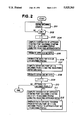
- machining profile is defined (step 1), followed by entry of data specifying an approach path for moving a wire electrode to a machining starting point on the machining profile (step 2).
- the machining conditions necessary for wire-cut electric discharge machining such as machining speed and wire offset diameter, are entered (step 3), as well as data specifying a departure path along which the wire electrode is retracted away from a machining end point on the machining profile (step 4).
- step 5 When entry of the data necessary for wire-cut electric discharge machining in accordance with the predetermined machining profile ends, a check is performed to determine whether to subject the workpiece to another machining operation (step 5). When machining is required, the processing from step 1 onward is repeated to again enter data specifying the machining profile, approach path, machining conditions and departure path. If it is not required to subject the workpiece to other machining, then the abovementioned entered data is used to successively originate NC program data for each and every machining profile (step 6).
- FIG. 5 shows views for describing the data which specifies the approach path, in which FIG. 5(a) is for a case in which a machining starting hole P a is decided at a position of distance l 1 on an extension ES of a first machining pass P F , a wire electrode 11 is fed at a cutting velocity F 1 along the extension ES from the machining starting hole P a to a starting point (machining starting point) P s of the first pass, after which the wire electrode is moved along the first pass PF (extension approach pattern).
- FIG. 5(a) is for a case in which a machining starting hole P a is decided at a position of distance l 1 on an extension ES of a first machining pass P F , a wire electrode 11 is fed at a cutting velocity F 1 along the extension ES from the machining starting hole P a to a starting point (machining starting point) P s of the first pass, after which the wire electrode is moved along the first pass PF (extension approach pattern).
- FIG. 5(b) is for a case in which the machining starting hole P a is decided at a position of distance l 1 on a tangent line TS to the first machining pass PF at the starting point (machining starting point) P s thereof, the wire electrode 11 is fed at the cutting velocity F 1 along the tangent line TS from the machining starting hole P a to the machining starting point P s , after which the wire electrode 11 is moved along the first pass PF (tangent line approach pattern).
- 5(c) is for a case in which the machining starting hole P a is decided at a position of distance l 1 on a tangent circle TC to the first machining pass PF at the starting point (machining starting point) P s thereof, the wire electrode 11 is fed at the cutting velocity F 1 along the tangent circle TC from the machining starting hole P a to the machining starting point P s , after which the wire electrode is moved along the first pass PF (tangent circle approach pattern).
- 5(d) is for a case in which the machining starting hole P a is decided at a position of distance l 1 on a normal line NS to the first machining pass PF at the starting point (machining starting point) P s thereof, the wire electrode 11 is fed at the cutting velocity F 1 along the normal line NS from the machining starting hole P a to the machining starting point P s , after which the wire electrode 11 is moved along the first pass PF (normal line approach pattern).
- FIG. 6 shows views for describing the data which specifies the departure path, in which FIG. 6(a) is for a case in which a wire departure point P a is decided at a position of distance l 1 on an extension ES of a last machining pass PL, the wire electrode 11 is retracted at the cutting velocity F 1 along the extension ES from the machining end point P e to the wire departure point P a (extension departure pattern).
- FIG. 6(a) is for a case in which a wire departure point P a is decided at a position of distance l 1 on an extension ES of a last machining pass PL
- the wire electrode 11 is retracted at the cutting velocity F 1 along the extension ES from the machining end point P e to the wire departure point P a (extension departure pattern).
- FIG. 6(b) is for a case in which the wire departure point P a is decided at a position of distance l 1 on a tangent line TS to the last machining pass PL at the end point (machining end point) P e thereof, and the wire electrode 11 is retracted at the cutting velocity F 1 along the tangent line TS from the machining end point P e to the wire point P a (tangent line departure pattern).
- FIG. 6(b) is for a case in which the wire departure point P a is decided at a position of distance l 1 on a tangent line TS to the last machining pass PL at the end point (machining end point) P e thereof, and the wire electrode 11 is retracted at the cutting velocity F 1 along the tangent line TS from the machining end point P e to the wire point P a (tangent line departure pattern).
- FIG. 6(c) is for a case in which the wire departure point P a is decided at a position of distance l 1 on a tangent circle TC to the last machining pass PL at the end point (machining end point) P e thereof, and the wire electrode 11 is retracted at the cutting velocity F 1 along the tangent circle TC from the machining end point P e to the wire departure point P a (tangent circle departure pattern).
- 6(d) is for a case in which the wire departure point P a is decided at a position of distance l 1 on a normal line NS to the last machining pass PL at the end point (machining end point) P e thereof, the wire electrode 11 is retracted at the cutting velocity F 1 along the normal line NS from the machining end point P e to the wire departure point P a (normal line departure pattern).
- an object of the present invention is to provide an automatic programming method involving NC program data for wire-cut electric discharge machining in which it is unnecessary to enter data for specifying approach paths, departure paths and other machining conditions.
- FIG. 1 is a block diagram of an automatic programming system to which the present invention can be applied;
- FIG. 2 is a flowchart of processing according to the invention.
- FIG. 3 is a view for describing the invention
- FIG. 4 is a flowchart of automatic programming processing according to the prior art.
- FIGS. 5(a-d) and 6(a-d) are views for describing an approach path, and departure path, respectively.
- FIG. 1 is a block diagram of an automatic programming system to which the present invention can be applied.
- Numeral 101 denotes a ROM in which a loading program is stored, 102 a processor, and 103 a RAM for storing (i) a system program for automatic programming, (ii) data for designating an approach path, machining conditions and a departure path in actual wire-cut electric discharge machining, and (iii) the results of processing.
- Numeral 104 denotes an NC data memory for storing originated NC program data, 105 a keyboard, 106 a graphic display unit (CRT), 107 a disk controller, and FL a floppy disk.
- CTR graphic display unit
- the data for specifying approach path are (i) data indicating the pattern from among those of FIGS. 5(a) through (d) in accordance with which an approach is to be made, (ii) the distance l 1 and (iii) the approach velocity F 1 .
- the data for specifying the departure path are (i) data indicating the pattern from among those of FIGS. 6(a) through (d) in accordance with which a departure is to be made, (ii) the distance l 1 and (iii) the departure velocity F 1 .
- FIG. 2 is a flowchart of processing according to the invention
- FIG. 3 is a view for describing the invention.
- the method of the invention will now be described in accordance with FIGS. 1 through 3. It is assumed that the system program SPR for automatic programming and the various data D AP , D ES , D MC stored on the floppy disk FL have already been loaded in a predetermined storage area of the RAM 103 by the loading program. Also, it is assumed that the extension approach pattern shown in FIG. 5(a) has been designated by the approach path data D AP , and that the tangent line departure pattern shown in FIG. 6(b) has been designated by the departure path data D ES .
- first machining profiles 51, 52, . . . , (see FIG. 3) that are mutually discontinuous are successively defined and entered (steps 201, 202) (see FIG. 2).
- the processor 102 When definition and entry of all machining profiles ends, the processor 102 performs the operation 1 ⁇ i (step 203) and computes the coordinates of an approach starting point (machining starting hole) P ai (see FIG. 3) of an i-th machining profile using the approach path data D AP and the path data of the first block of the i-th machining profile stored in the RAM 103 (step 204).
- NC data for the approach from the machining starting hole P ai to a machining starting point P si of the i-th machining profile are originated (step 205), then the machining conditions and i-th machining profile data stored in the RAM 103 are used to originate path NC data for moving the wire electrode along the i-th machining profile (step 206).
- the processor 102 computes the coordinates of a wire departure starting point P ei of the i-th machining profile using the departure path data D ES and the path data of the last block of the i-th machining profile stored in the RAM 103 (step 207). NC data for departure from the machining end point to the wire departure point P ei are then created (step 208).
- i is incremented by the operation i+1 ⁇ i (step 209), after which a check is performed to determine if an i-th machining profile exists (step 210). If an i-th machining profile does not exist, automatic programming processing ends.
- coordinates of the approach starting point (machining starting hole) P ai of the i-th machining profile are computed using the approach path data D AP and the path data of the first block of the i-th machining profile stored in the RAM 103 (step 211).
- the processor 102 subsequently originates:
- step 212 a code (MOO) for automatic connection of the wire electrode (step 212). Thereafter, processing from step 205 onward is repeated to originate NC data for the i-th machining profile.
- the approach path and departure path of each machining profile can be decided in accordance with exactly the same reference as set forth above is that the approach path, machining conditions and departure path in wire-cut electric discharge machining are decided in dependence upon, e.g., the degree of machining precision, and are not influenced by the machining profile.
- approach path, machining conditions and departure path are registered in advance.
- the arrangement is such that only machining profiles are defined, it being unnecessary to enter the abovementioned approach path, machining conditions and departure path.
- the data input operation is simplified.
- the operator can give undivided attention solely to the definition of machining profile. This makes it possible to reduce operation errors in originating NC data.
Abstract
In an automatic programming apparatus involving NC program data for wire-cut electric discharge machining according to the invention, data specifying an approach path and a departure path, as well as wire-cut machining conditions, are registered in advance. In automatic programming, rather than entering an approach path, departure path and machining conditions separately, only machining profiles (51, 52, . . . ) are successively defined, after which the machining profile data and the registered data are used to originate, for each and every machining profile (51, 52, . . . ), (i) approach NC data, (ii) NC data for moving a wire electrode along the machining profiles (51, 52, . . . ), and (iii) departure NC data.
Description
This invention relates to an automatic programming method and, more particularly, to a method of automatically originating NC program data for wire-cut electric discharge machining.
In the origination of NC data for wire-cut electric discharge machining, automatic programming is performed in accordance with a procedure of the kind shown in FIG. 4 according to the prior art. Specifically, a machining profile is defined (step 1), followed by entry of data specifying an approach path for moving a wire electrode to a machining starting point on the machining profile (step 2). Next, the machining conditions necessary for wire-cut electric discharge machining, such as machining speed and wire offset diameter, are entered (step 3), as well as data specifying a departure path along which the wire electrode is retracted away from a machining end point on the machining profile (step 4). When entry of the data necessary for wire-cut electric discharge machining in accordance with the predetermined machining profile ends, a check is performed to determine whether to subject the workpiece to another machining operation (step 5). When machining is required, the processing from step 1 onward is repeated to again enter data specifying the machining profile, approach path, machining conditions and departure path. If it is not required to subject the workpiece to other machining, then the abovementioned entered data is used to successively originate NC program data for each and every machining profile (step 6).
FIG. 5 shows views for describing the data which specifies the approach path, in which FIG. 5(a) is for a case in which a machining starting hole Pa is decided at a position of distance l1 on an extension ES of a first machining pass PF, a wire electrode 11 is fed at a cutting velocity F1 along the extension ES from the machining starting hole Pa to a starting point (machining starting point) Ps of the first pass, after which the wire electrode is moved along the first pass PF (extension approach pattern). FIG. 5(b) is for a case in which the machining starting hole Pa is decided at a position of distance l1 on a tangent line TS to the first machining pass PF at the starting point (machining starting point) Ps thereof, the wire electrode 11 is fed at the cutting velocity F1 along the tangent line TS from the machining starting hole Pa to the machining starting point Ps, after which the wire electrode 11 is moved along the first pass PF (tangent line approach pattern). FIG. 5(c) is for a case in which the machining starting hole Pa is decided at a position of distance l1 on a tangent circle TC to the first machining pass PF at the starting point (machining starting point) Ps thereof, the wire electrode 11 is fed at the cutting velocity F1 along the tangent circle TC from the machining starting hole Pa to the machining starting point Ps, after which the wire electrode is moved along the first pass PF (tangent circle approach pattern). FIG. 5(d) is for a case in which the machining starting hole Pa is decided at a position of distance l1 on a normal line NS to the first machining pass PF at the starting point (machining starting point) Ps thereof, the wire electrode 11 is fed at the cutting velocity F1 along the normal line NS from the machining starting hole Pa to the machining starting point Ps, after which the wire electrode 11 is moved along the first pass PF (normal line approach pattern).
FIG. 6 shows views for describing the data which specifies the departure path, in which FIG. 6(a) is for a case in which a wire departure point Pa is decided at a position of distance l1 on an extension ES of a last machining pass PL, the wire electrode 11 is retracted at the cutting velocity F1 along the extension ES from the machining end point Pe to the wire departure point Pa (extension departure pattern). FIG. 6(b) is for a case in which the wire departure point Pa is decided at a position of distance l1 on a tangent line TS to the last machining pass PL at the end point (machining end point) Pe thereof, and the wire electrode 11 is retracted at the cutting velocity F1 along the tangent line TS from the machining end point Pe to the wire point Pa (tangent line departure pattern). FIG. 6(c) is for a case in which the wire departure point Pa is decided at a position of distance l1 on a tangent circle TC to the last machining pass PL at the end point (machining end point) Pe thereof, and the wire electrode 11 is retracted at the cutting velocity F1 along the tangent circle TC from the machining end point Pe to the wire departure point Pa (tangent circle departure pattern). FIG. 6(d) is for a case in which the wire departure point Pa is decided at a position of distance l1 on a normal line NS to the last machining pass PL at the end point (machining end point) Pe thereof, the wire electrode 11 is retracted at the cutting velocity F1 along the normal line NS from the machining end point Pe to the wire departure point Pa (normal line departure pattern).
In this conventional automatic programming method involving NC data for wire-cut electric discharge machining, (i) the data for specifying the approach path, (ii) the machining condition data and (iii) the data for specifying the departure path are entered separately each time a machining profile is entered. Consequently, data entry requires time; the greater the number of machining profiles, the longer the time needed. Also, the NC data automatic programming operation is a complicated one and operation errors occur.
Accordingly, an object of the present invention is to provide an automatic programming method involving NC program data for wire-cut electric discharge machining in which it is unnecessary to enter data for specifying approach paths, departure paths and other machining conditions.
Data specifying an approach path and a departure path, as well as wire-cut machining conditions, are registered in advance. In automatic programming, rather than entering an approach path, departure path and machining conditions separately, only machining profiles (51, 52, . . . ,) (see FIG. 3) are successively defined, after which the machining profile data and the registered approach path data, departure path data and machining condition data are used to originate NC program data for wire-cut electric discharge machining for each and every profile (51, 52).
FIG. 1 is a block diagram of an automatic programming system to which the present invention can be applied;
FIG. 2 is a flowchart of processing according to the invention;
FIG. 3 is a view for describing the invention;
FIG. 4 is a flowchart of automatic programming processing according to the prior art; and
FIGS. 5(a-d) and 6(a-d) are views for describing an approach path, and departure path, respectively.
FIG. 1 is a block diagram of an automatic programming system to which the present invention can be applied. Numeral 101 denotes a ROM in which a loading program is stored, 102 a processor, and 103 a RAM for storing (i) a system program for automatic programming, (ii) data for designating an approach path, machining conditions and a departure path in actual wire-cut electric discharge machining, and (iii) the results of processing. Numeral 104 denotes an NC data memory for storing originated NC program data, 105 a keyboard, 106 a graphic display unit (CRT), 107 a disk controller, and FL a floppy disk. Registered on the floppy disk FL in advance are (i) a system program SPR for originating NC program data for wire-cut electric discharge machining, and (ii) approach path data DAP, departure path data DES and various data for specifying machining conditions DMC.
The data for specifying approach path are (i) data indicating the pattern from among those of FIGS. 5(a) through (d) in accordance with which an approach is to be made, (ii) the distance l1 and (iii) the approach velocity F1. The data for specifying the departure path are (i) data indicating the pattern from among those of FIGS. 6(a) through (d) in accordance with which a departure is to be made, (ii) the distance l1 and (iii) the departure velocity F1.
FIG. 2 is a flowchart of processing according to the invention, and FIG. 3 is a view for describing the invention. The method of the invention will now be described in accordance with FIGS. 1 through 3. It is assumed that the system program SPR for automatic programming and the various data DAP, DES, DMC stored on the floppy disk FL have already been loaded in a predetermined storage area of the RAM 103 by the loading program. Also, it is assumed that the extension approach pattern shown in FIG. 5(a) has been designated by the approach path data DAP, and that the tangent line departure pattern shown in FIG. 6(b) has been designated by the departure path data DES.
In originating NC data for wire-cut electric discharge machining, first machining profiles 51, 52, . . . , (see FIG. 3) that are mutually discontinuous are successively defined and entered (steps 201, 202) (see FIG. 2).
When definition and entry of all machining profiles ends, the processor 102 performs the operation 1→i (step 203) and computes the coordinates of an approach starting point (machining starting hole) Pai (see FIG. 3) of an i-th machining profile using the approach path data DAP and the path data of the first block of the i-th machining profile stored in the RAM 103 (step 204).
Thereafter, NC data for the approach from the machining starting hole Pai to a machining starting point Psi of the i-th machining profile are originated (step 205), then the machining conditions and i-th machining profile data stored in the RAM 103 are used to originate path NC data for moving the wire electrode along the i-th machining profile (step 206).
When the origination of the path NC data is finished, the processor 102 computes the coordinates of a wire departure starting point Pei of the i-th machining profile using the departure path data DES and the path data of the last block of the i-th machining profile stored in the RAM 103 (step 207). NC data for departure from the machining end point to the wire departure point Pei are then created (step 208).
When the origination of the NC data for the i-th machining profile ends, i is incremented by the operation i+1→i (step 209), after which a check is performed to determine if an i-th machining profile exists (step 210). If an i-th machining profile does not exist, automatic programming processing ends.
On the other hand, if an i-th machining profile does exist, coordinates of the approach starting point (machining starting hole) Pai of the i-th machining profile are computed using the approach path data DAP and the path data of the first block of the i-th machining profile stored in the RAM 103 (step 211).
The processor 102 subsequently originates:
(i) an M code (M□□) for wire severance;
(ii) NC data for positioning the wire electrode relative to the workpiece from a departure point Pe(i- 1) of an (i-1)th machining profile to the machining starting hole Pai of the i-th machining profile in a rapid-traverse mode; and
(iii) a code (MOO) for automatic connection of the wire electrode (step 212). Thereafter, processing from step 205 onward is repeated to originate NC data for the i-th machining profile.
It should be noted that the reason why the approach path and departure path of each machining profile can be decided in accordance with exactly the same reference as set forth above is that the approach path, machining conditions and departure path in wire-cut electric discharge machining are decided in dependence upon, e.g., the degree of machining precision, and are not influenced by the machining profile.
In accordance with the present invention as described above, approach path, machining conditions and departure path are registered in advance. In the origination of NC data for wire-cut electric discharge machining, the arrangement is such that only machining profiles are defined, it being unnecessary to enter the abovementioned approach path, machining conditions and departure path. As a result, the data input operation is simplified. In addition, the operator can give undivided attention solely to the definition of machining profile. This makes it possible to reduce operation errors in originating NC data.
Claims (8)
1. An automatic programming method involving NC program data for wire=cut electric discharge machining, comprising the steps of:
(a) presetting data for specifying an approach path, a departure path and wire-cut electric discharge machining conditions;
(b) successively setting two or more machining profiles; and
(c) creating, for each of said machining profiles and after step (b), approach NC data, NC data for moving a wire electrode along the machining profile, and departure NC data using the machining profile and said preset data.
2. An automatic programming method involving NC program data for wire-cut electric discharge machining, comprising the steps of:
(a) presetting data for specifying an approach path, a departure path and wire-cut electric discharge machining conditions, including the sub-steps of
specifying an approach path pattern, a distance between an approach starting point and a machining starting point, and an approach velocity;
(b) successively setting two or more machining profiles; and
(c) creating, for each of said machining profiles and after step (b), approach NC data, NC data for moving a wire electrode along the machining profile, and departure NC data using the machining profile and said preset data, including the sub-steps of
determining coordinates of the approach starting point for each of said machining profiles based on said approach path data and a first block of path data of the machining profile, and
creating said approach NC data for causing said wire electrode to approach the machining starting point from the approach starting point along the approach path pattern.
3. An automatic programming method involving NC program data for wire-cut electric discharge machining, comprising the steps of:
(a) presetting data for specifying an approach path, a departure path and wire-cut electric discharge machining conditions, including the sub-steps of
specifying a departure path pattern, a distance between a machining end point and a departure point, and a departure velocity;
(b) successively setting two or more machining profiles; and
(c) creating, for each of said machining profiles and after step (b), approach NC data, NC data for moving a wire electrode along the machining profile, and departure NC data using the machining profile and said preset data, including the sub-steps of
determining coordinates of the departure starting point for each of said machining profiles based on said departure path data and a last block of path data of the machining profile, and
creating said departure NC data for causing said wire electrode to depart from the machining end point to the departure point along the departure path pattern.
4. An automatic programming method involving NC program data for wire-cut electric discharge machining, comprising the steps of:
(a) presetting data for specifying an approach path, a departure path and wire-cut electric discharge machining conditions;
(b) successively setting two or more machining profiles;
(c) creating, for each of said machining profiles and after step (b), approach NC data, NC data for moving a wire electrode along the machining profile, and departure NC data using the machining profile and said preset data; and
(d) creating NC data for rapid-traverse of said wire electrode from a departure point of one of said machining profiles to an approach point of another of said machining profiles in a rapid-traverse mode.
5. An automatic programming method involving NC program data for wire-cut electric discharge machining, comprising the steps of:
(a) presetting data for specifying an approach path, a departure path and wire-cut electric discharge machining conditions;
(b) successively setting two or more machining profiles;
(c) creating, for each of said machining profiles and after step (b), approach NC data, NC data for moving a wire electrode along the machining profile, and departure NC data using the machining profile and said preset data;
(d) creating NC data for rapid-traverse of said wire electrode from a departure point of one of said machining profiles to an approach point of one of said machining profiles in a rapid-traverse mode;
(e) creating a command for wire severance before creating said NC data for rapid-traverse; and
(f) creating a command for automatic wire connection after creating said NC data for rapid-traverse.
6. An automatic programming method for wire-cut electric discharge machining using a processor and a memory, comprising the steps of:
(a) presetting in the memory, data for specifying an approach path, a departure path and wire-cut electric discharge machining conditions;
(b) successively defining in the memory, a plurality of machining profiles; and
(c) creating in the processor after step (b), based upon one of said machining profiles defined in step (b) and said data preset in step (a), approach NC data, NC data for moving a wire electrode along said one machining profile, and departure NC data for said one machining profile.
7. A method for wire-cut electric discharge machining using a processor and a memory, comprising the steps of;
(a) presetting in the memory, data for specifying an approach path, a departure path and wire-cut electric discharge machining conditions;
(b) successively defining in the memory, a plurality of machining profiles;
(c) creating in the processor after step (b), based upon one of said machining profiles defined in step (b) and said data preset in step (a), approach NC data, NC data for moving a wire electrode along said one machining profile, and departure NC data for said one machining profile; and
(d) repeating step (c) for another machining profile.
8. An apparatus for automatically programming NC program data for wire-cut electric discharge machining, comprising:
means for presetting data specifying an approach path, a departure path and wire-cut electric discharge machining conditions;
means for defining a plurality of machining profiles; and means for creating after said machining profiles have been defined, based upon said machining profiles and said preset data, approach NC data, NC data for moving a wire electrode along the machining profile, and departure NC data for each of said machining profiles.
Applications Claiming Priority (2)
| Application Number | Priority Date | Filing Date | Title |
|---|---|---|---|
| JP62178091A JPS6421506A (en) | 1987-07-16 | 1987-07-16 | Auto-programming system |
| JP62-178091 | 1987-07-16 |
Publications (1)
| Publication Number | Publication Date |
|---|---|
| US5025363A true US5025363A (en) | 1991-06-18 |
Family
ID=16042477
Family Applications (1)
| Application Number | Title | Priority Date | Filing Date |
|---|---|---|---|
| US07/320,091 Expired - Fee Related US5025363A (en) | 1987-07-16 | 1988-07-15 | Automatic programming method |
Country Status (4)
| Country | Link |
|---|---|
| US (1) | US5025363A (en) |
| EP (1) | EP0328657A4 (en) |
| JP (1) | JPS6421506A (en) |
| WO (1) | WO1989000475A1 (en) |
Cited By (3)
| Publication number | Priority date | Publication date | Assignee | Title |
|---|---|---|---|---|
| US5184294A (en) * | 1989-04-28 | 1993-02-02 | Kabushiki Kaisha Okuma Tekkosho | Apparatus for generating numerical control information for machining parts |
| US6333092B1 (en) | 1999-02-25 | 2001-12-25 | The United States Of America As Represented By The Secretary Of The Navy | Fractal interfacial enhancement of composite delamination resistance |
| US20080201010A1 (en) * | 2007-02-20 | 2008-08-21 | Fanuc Ltd | Punch machining program generating device, recording medium storing a program for generating a punch machining program, and wire-cut electric discharge machine |
Families Citing this family (4)
| Publication number | Priority date | Publication date | Assignee | Title |
|---|---|---|---|---|
| JPH01205929A (en) * | 1988-02-15 | 1989-08-18 | Fanuc Ltd | Preparation of nc data |
| JPH03164908A (en) * | 1989-11-24 | 1991-07-16 | Okuma Mach Works Ltd | Generating device for numerical control program |
| DE4107527C2 (en) * | 1991-03-08 | 1994-11-17 | Gaese Martin | Wire EDM process |
| JP4098761B2 (en) * | 2004-08-17 | 2008-06-11 | ファナック株式会社 | Finishing method |
Citations (4)
| Publication number | Priority date | Publication date | Assignee | Title |
|---|---|---|---|---|
| US4587608A (en) * | 1982-10-30 | 1986-05-06 | Fanuc Ltd. | Method of automatically creating numerical control data in one of a plurality of data formats |
| US4604705A (en) * | 1982-12-29 | 1986-08-05 | Mitsubishi Denki Kabushiki Kaisha | Numerical control machining method and system therefor |
| US4704687A (en) * | 1983-02-17 | 1987-11-03 | Fanuc Ltd | Method for constructioning tool approach and retraction paths from preset patterns |
| US4799143A (en) * | 1985-07-22 | 1989-01-17 | Fanuc Ltd. | NC data creation method |
Family Cites Families (5)
| Publication number | Priority date | Publication date | Assignee | Title |
|---|---|---|---|---|
| JPS59211105A (en) * | 1983-05-17 | 1984-11-29 | Fanuc Ltd | Producing method of part program |
| JPH0760334B2 (en) * | 1985-09-20 | 1995-06-28 | 松下電工株式会社 | Parts processing CAM system for NC processing machines |
| JPS62120507A (en) * | 1985-11-21 | 1987-06-01 | Mitsubishi Electric Corp | Method for preparing numerical control program of numerical controller |
| JPS62140747A (en) * | 1985-12-14 | 1987-06-24 | Hitachi Seiki Co Ltd | Setting device for machining condition in automatic machine |
| JP2902232B2 (en) * | 1992-11-19 | 1999-06-07 | 日東電工株式会社 | Pressure-sensitive adhesive composition and pressure-sensitive adhesive tape using the same |
-
1987
- 1987-07-16 JP JP62178091A patent/JPS6421506A/en active Pending
-
1988
- 1988-07-15 US US07/320,091 patent/US5025363A/en not_active Expired - Fee Related
- 1988-07-15 EP EP19880906092 patent/EP0328657A4/en not_active Withdrawn
- 1988-07-15 WO PCT/JP1988/000704 patent/WO1989000475A1/en not_active Application Discontinuation
Patent Citations (4)
| Publication number | Priority date | Publication date | Assignee | Title |
|---|---|---|---|---|
| US4587608A (en) * | 1982-10-30 | 1986-05-06 | Fanuc Ltd. | Method of automatically creating numerical control data in one of a plurality of data formats |
| US4604705A (en) * | 1982-12-29 | 1986-08-05 | Mitsubishi Denki Kabushiki Kaisha | Numerical control machining method and system therefor |
| US4704687A (en) * | 1983-02-17 | 1987-11-03 | Fanuc Ltd | Method for constructioning tool approach and retraction paths from preset patterns |
| US4799143A (en) * | 1985-07-22 | 1989-01-17 | Fanuc Ltd. | NC data creation method |
Cited By (4)
| Publication number | Priority date | Publication date | Assignee | Title |
|---|---|---|---|---|
| US5184294A (en) * | 1989-04-28 | 1993-02-02 | Kabushiki Kaisha Okuma Tekkosho | Apparatus for generating numerical control information for machining parts |
| US6333092B1 (en) | 1999-02-25 | 2001-12-25 | The United States Of America As Represented By The Secretary Of The Navy | Fractal interfacial enhancement of composite delamination resistance |
| US6663803B1 (en) | 1999-02-25 | 2003-12-16 | The United States Of America As Represented By The Secretary Of The Navy | Fabrication of a fractally attributively delamination resistive composite structure |
| US20080201010A1 (en) * | 2007-02-20 | 2008-08-21 | Fanuc Ltd | Punch machining program generating device, recording medium storing a program for generating a punch machining program, and wire-cut electric discharge machine |
Also Published As
| Publication number | Publication date |
|---|---|
| EP0328657A1 (en) | 1989-08-23 |
| EP0328657A4 (en) | 1991-07-31 |
| JPS6421506A (en) | 1989-01-24 |
| WO1989000475A1 (en) | 1989-01-26 |
Similar Documents
| Publication | Publication Date | Title |
|---|---|---|
| US4513366A (en) | Menu programmed machine tool numerical controller with an interference checking function | |
| EP0166783B1 (en) | Machining step determination method for automatic programming | |
| US4878172A (en) | Four-axis lathe NC program creation method | |
| US5025363A (en) | Automatic programming method | |
| JPH0252282B2 (en) | ||
| US4977512A (en) | Three dimensional simultaneous machining and measuring system | |
| US4998196A (en) | Method of creating NC data for turning | |
| EP0137047A1 (en) | Method of determining three-dimensional tool path | |
| US4698573A (en) | Numerically controlled working process | |
| US5387852A (en) | Method of determining tool running path in N/C system | |
| US5175407A (en) | Nc data creation method | |
| US5044842A (en) | Round screw thread machining method | |
| US5177690A (en) | Method of creating no data for hole machining | |
| US4672551A (en) | Die machining apparatus in automatic programming | |
| EP0335975B1 (en) | Method of preparing nc data | |
| JPH0773818B2 (en) | Automatic machining range determination method in turning and automatic programming system for lathes | |
| US5383131A (en) | Method of determining cutting trajectory in N/C machining system | |
| JP2768239B2 (en) | Wire electric discharge machine | |
| JP3328150B2 (en) | Tool path data generation method | |
| EP0139762A1 (en) | Method of specifying shape of blank | |
| JP3248081B2 (en) | Automatic program creation device with automatic cutting axis change function | |
| JP2798549B2 (en) | Automatic determination of internal machining tools | |
| JPH1029080A (en) | Automatic programming device of laser beam machine | |
| JP2764941B2 (en) | Setting the cutter path | |
| JPH06102914A (en) | Method for generating machining program for numerical controller |
Legal Events
| Date | Code | Title | Description |
|---|---|---|---|
| AS | Assignment |
Owner name: FANUC LTD., A CORP. OF JAPAN, JAPAN Free format text: ASSIGNMENT OF ASSIGNORS INTEREST.;ASSIGNORS:SEKI, MASAKI;TAKEGAHARA, TAKASHI;NAKAJIMA, MASATOSHI;REEL/FRAME:005081/0209 Effective date: 19890222 |
|
| CC | Certificate of correction | ||
| FEPP | Fee payment procedure |
Free format text: PAYOR NUMBER ASSIGNED (ORIGINAL EVENT CODE: ASPN); ENTITY STATUS OF PATENT OWNER: LARGE ENTITY |
|
| REMI | Maintenance fee reminder mailed | ||
| LAPS | Lapse for failure to pay maintenance fees | ||
| FP | Lapsed due to failure to pay maintenance fee |
Effective date: 19950621 |
|
| STCH | Information on status: patent discontinuation |
Free format text: PATENT EXPIRED DUE TO NONPAYMENT OF MAINTENANCE FEES UNDER 37 CFR 1.362 |