US4975050A - Workpiece heating and feeding device - Google Patents
Workpiece heating and feeding device Download PDFInfo
- Publication number
- US4975050A US4975050A US07/374,533 US37453389A US4975050A US 4975050 A US4975050 A US 4975050A US 37453389 A US37453389 A US 37453389A US 4975050 A US4975050 A US 4975050A
- Authority
- US
- United States
- Prior art keywords
- lid
- workpiece
- heating block
- feeding
- heat
- Prior art date
- Legal status (The legal status is an assumption and is not a legal conclusion. Google has not performed a legal analysis and makes no representation as to the accuracy of the status listed.)
- Expired - Lifetime
Links
- 238000010438 heat treatment Methods 0.000 title claims abstract description 43
- 210000000078 claw Anatomy 0.000 claims description 8
- 239000011521 glass Substances 0.000 claims description 2
- 239000000428 dust Substances 0.000 abstract description 7
- 239000003779 heat-resistant material Substances 0.000 abstract description 4
- XEEYBQQBJWHFJM-UHFFFAOYSA-N Iron Chemical compound [Fe] XEEYBQQBJWHFJM-UHFFFAOYSA-N 0.000 description 6
- 239000007789 gas Substances 0.000 description 4
- 238000012423 maintenance Methods 0.000 description 4
- 239000011261 inert gas Substances 0.000 description 3
- 229910052742 iron Inorganic materials 0.000 description 3
- 230000003647 oxidation Effects 0.000 description 3
- 238000007254 oxidation reaction Methods 0.000 description 3
- 230000000694 effects Effects 0.000 description 2
- 239000000463 material Substances 0.000 description 2
- RYGMFSIKBFXOCR-UHFFFAOYSA-N Copper Chemical compound [Cu] RYGMFSIKBFXOCR-UHFFFAOYSA-N 0.000 description 1
- 229910052802 copper Inorganic materials 0.000 description 1
- 239000010949 copper Substances 0.000 description 1
- 230000002939 deleterious effect Effects 0.000 description 1
- 238000002845 discoloration Methods 0.000 description 1
- 238000004519 manufacturing process Methods 0.000 description 1
- 238000000034 method Methods 0.000 description 1
- 230000000149 penetrating effect Effects 0.000 description 1
- 230000035515 penetration Effects 0.000 description 1
- 239000004065 semiconductor Substances 0.000 description 1
Images


Classifications
-
- H—ELECTRICITY
- H01—ELECTRIC ELEMENTS
- H01L—SEMICONDUCTOR DEVICES NOT COVERED BY CLASS H10
- H01L21/00—Processes or apparatus adapted for the manufacture or treatment of semiconductor or solid state devices or of parts thereof
- H01L21/67—Apparatus specially adapted for handling semiconductor or electric solid state devices during manufacture or treatment thereof; Apparatus specially adapted for handling wafers during manufacture or treatment of semiconductor or electric solid state devices or components ; Apparatus not specifically provided for elsewhere
- H01L21/68—Apparatus specially adapted for handling semiconductor or electric solid state devices during manufacture or treatment thereof; Apparatus specially adapted for handling wafers during manufacture or treatment of semiconductor or electric solid state devices or components ; Apparatus not specifically provided for elsewhere for positioning, orientation or alignment
-
- H—ELECTRICITY
- H01—ELECTRIC ELEMENTS
- H01L—SEMICONDUCTOR DEVICES NOT COVERED BY CLASS H10
- H01L21/00—Processes or apparatus adapted for the manufacture or treatment of semiconductor or solid state devices or of parts thereof
- H01L21/67—Apparatus specially adapted for handling semiconductor or electric solid state devices during manufacture or treatment thereof; Apparatus specially adapted for handling wafers during manufacture or treatment of semiconductor or electric solid state devices or components ; Apparatus not specifically provided for elsewhere
- H01L21/67005—Apparatus not specifically provided for elsewhere
- H01L21/67011—Apparatus for manufacture or treatment
- H01L21/67144—Apparatus for mounting on conductive members, e.g. leadframes or conductors on insulating substrates
-
- F—MECHANICAL ENGINEERING; LIGHTING; HEATING; WEAPONS; BLASTING
- F27—FURNACES; KILNS; OVENS; RETORTS
- F27B—FURNACES, KILNS, OVENS, OR RETORTS IN GENERAL; OPEN SINTERING OR LIKE APPARATUS
- F27B17/00—Furnaces of a kind not covered by any preceding group
- F27B17/0016—Chamber type furnaces
- F27B17/0025—Especially adapted for treating semiconductor wafers
-
- H—ELECTRICITY
- H01—ELECTRIC ELEMENTS
- H01L—SEMICONDUCTOR DEVICES NOT COVERED BY CLASS H10
- H01L21/00—Processes or apparatus adapted for the manufacture or treatment of semiconductor or solid state devices or of parts thereof
- H01L21/02—Manufacture or treatment of semiconductor devices or of parts thereof
- H01L21/04—Manufacture or treatment of semiconductor devices or of parts thereof the devices having potential barriers, e.g. a PN junction, depletion layer or carrier concentration layer
- H01L21/50—Assembly of semiconductor devices using processes or apparatus not provided for in a single one of the subgroups H01L21/06 - H01L21/326, e.g. sealing of a cap to a base of a container
-
- H—ELECTRICITY
- H01—ELECTRIC ELEMENTS
- H01L—SEMICONDUCTOR DEVICES NOT COVERED BY CLASS H10
- H01L2224/00—Indexing scheme for arrangements for connecting or disconnecting semiconductor or solid-state bodies and methods related thereto as covered by H01L24/00
- H01L2224/74—Apparatus for manufacturing arrangements for connecting or disconnecting semiconductor or solid-state bodies and for methods related thereto
- H01L2224/78—Apparatus for connecting with wire connectors
- H01L2224/7825—Means for applying energy, e.g. heating means
- H01L2224/783—Means for applying energy, e.g. heating means by means of pressure
- H01L2224/78301—Capillary
-
- H—ELECTRICITY
- H01—ELECTRIC ELEMENTS
- H01L—SEMICONDUCTOR DEVICES NOT COVERED BY CLASS H10
- H01L2924/00—Indexing scheme for arrangements or methods for connecting or disconnecting semiconductor or solid-state bodies as covered by H01L24/00
- H01L2924/0001—Technical content checked by a classifier
- H01L2924/00014—Technical content checked by a classifier the subject-matter covered by the group, the symbol of which is combined with the symbol of this group, being disclosed without further technical details
-
- H—ELECTRICITY
- H01—ELECTRIC ELEMENTS
- H01L—SEMICONDUCTOR DEVICES NOT COVERED BY CLASS H10
- H01L2924/00—Indexing scheme for arrangements or methods for connecting or disconnecting semiconductor or solid-state bodies as covered by H01L24/00
- H01L2924/01—Chemical elements
- H01L2924/01005—Boron [B]
-
- H—ELECTRICITY
- H01—ELECTRIC ELEMENTS
- H01L—SEMICONDUCTOR DEVICES NOT COVERED BY CLASS H10
- H01L2924/00—Indexing scheme for arrangements or methods for connecting or disconnecting semiconductor or solid-state bodies as covered by H01L24/00
- H01L2924/01—Chemical elements
- H01L2924/01006—Carbon [C]
-
- H—ELECTRICITY
- H01—ELECTRIC ELEMENTS
- H01L—SEMICONDUCTOR DEVICES NOT COVERED BY CLASS H10
- H01L2924/00—Indexing scheme for arrangements or methods for connecting or disconnecting semiconductor or solid-state bodies as covered by H01L24/00
- H01L2924/01—Chemical elements
- H01L2924/01029—Copper [Cu]
-
- H—ELECTRICITY
- H01—ELECTRIC ELEMENTS
- H01L—SEMICONDUCTOR DEVICES NOT COVERED BY CLASS H10
- H01L2924/00—Indexing scheme for arrangements or methods for connecting or disconnecting semiconductor or solid-state bodies as covered by H01L24/00
- H01L2924/01—Chemical elements
- H01L2924/01033—Arsenic [As]
-
- H—ELECTRICITY
- H01—ELECTRIC ELEMENTS
- H01L—SEMICONDUCTOR DEVICES NOT COVERED BY CLASS H10
- H01L2924/00—Indexing scheme for arrangements or methods for connecting or disconnecting semiconductor or solid-state bodies as covered by H01L24/00
- H01L2924/01—Chemical elements
- H01L2924/01039—Yttrium [Y]
-
- H—ELECTRICITY
- H01—ELECTRIC ELEMENTS
- H01L—SEMICONDUCTOR DEVICES NOT COVERED BY CLASS H10
- H01L2924/00—Indexing scheme for arrangements or methods for connecting or disconnecting semiconductor or solid-state bodies as covered by H01L24/00
- H01L2924/01—Chemical elements
- H01L2924/01082—Lead [Pb]
Definitions
- the present invention relates to a workpiece heating and feeding device which can be used in wire bonders, die bonders or curing devices that are used in the manufacture of semiconductor devices.
- workpiece heating and feeding devices used in bonders consist of three general types.
- the three types are (a) devices in which the area above the heating block that heats the workpieces (e.g. the lead frames, etc.) is open (as shown in FIG. 3), (b) devices in which the area above the heating block is closed (as shown in FIG. 4) or (c) devices in which the entire periphery of the heating block is sealed off (as shown in FIG. 5).
- the device shown in FIG. 3 (wherein the area above the heating block is open) is the most common type of device used.
- a split lid 5 is fastened to guide rails 3 which guide the workpieces 1, so that the workpieces 1 will not float upward as they are fed by the feeding claws 4. In other words, nothing is installed above the central portions of the workpieces 1 portions of the workpieces are left exposed.
- Such a device operates in the following manner.
- the feeding claws 4 With the heating block 2 in a lowered position, the feeding claws 4 are caused to complete a cycle in which the claws 4 are lowered and, caused to complete a forward motion in the horizontal direction (perpendicular to the plane of the paper as shown in FIG. 3), raised and caused to complete a return motion in the horizontal direction.
- the workpieces 1 are fed by one pitch.
- the heating block 2 is raised, so that each workpiece is heated.
- the device illustrated in FIG. 4 (wherein the area above the heating block is closed) is used in cases where the workpieces 1 or leads formed on the workpieces 1 consist of materials which are easily oxidizable such as copper materials.
- the heating block 2 is arranged so that it guides the workpieces 1, and an integral lid (that is, a lid consisting of one piece) made of iron is fastened to the heating block 2 itself.
- Grooves 2a are formed in the upper surface of the heating block 2, and the pipes 6 are installed in these grooves 2a so that the pipes can move upward and downward.
- the system is arranged so that an inert gas may be introduced and caused to flow over the upper surface of the heating block 2 from the pipes 6.
- This device operates as follows: After the pipes 6 are raised so that the workpieces 1 are caused to float above the heating block 2, each workpiece 1 is fed a distance of one pitch by the feeding claws 4. Afterward, the pipes 6 are lowered so that the workpieces 1 rest on the surface of the heating block 2 and the workpieces 1 are thus heated. As a result of the inert gas flowing from the pipes 6, the area above the heating block 2 is filled with an inert gas thus preventing oxidation of the workpieces 1.
- the device illustrated in FIG. 5 also prevents oxidation of the workpieces in the same manner as the device illustrated in FIG. 4.
- an integral lid 5 that is, a one piece lid
- a housing 7 which guides the workpieces 1 so that the lid 5 covers the heating block 2.
- Holes 2b which allow the flow of insert gas are formed in the heating block 2 parallel to the feeding direction of the workpiece 1. These holes 2b are connected with the upper surface of the heating block 2 by holes 2c.
- a gas atmosphere is created above the heating block 2 by causing insert gas to flow through the holes 2b from gas supplying ports (not shown).
- the heating block 2 is arranged so that it can be driven upward and downward. As in the case of the device illustrated in FIG. 3, the heating block 2 is lowered while the workpieces 1 are being fed. After the workpieces 1 have been fed, the heating block 2 is raised, and the workpieces 1 are heated.
- a bonding window is formed in a portion of the lid 5 which corresponds to the position of the bonding tool in the devices shown in FIGS. 4 and 5.
- the present invention provides a workpiece heating and feeding device in which a lid is installed above a heating block that heats the workpiece.
- a lid is installed above a heating block that heats the workpiece.
- an opening is formed in the central portion of the lid and a transparent heat-resistant plate is attached so that the plate covers the opening.
- the objects of the present invention can be achieved by making the lid covering the heating block of a transparent heat-resistant plate.
- the condition of the workpieces can be monitored.
- adjustment of the feeding rate of the workpieces and maintenance of the device can be readily facilitated.
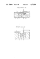
- FIG. 1(a) is a plan view of one embodiment of the present invention
- FIG. 1(b) is a cross-sectional view taken along the line A--A of FIG. 1(a);
- FIG. 2 is a cross-sectional view illustrating another embodiment of the present invention.
- FIGS. 3, 4 and 5 are cross-sectional views of conventional workpiece heating and feeding devices.
- FIGS. 1(a) and 1(b) the embodiment shown therein is an open type device (as shown in FIG. 3 of the prior art).
- elements which correspond to those elements of FIG. 3 are given the same reference numerals.
- a split lid 10 is fastened to the surfaces of guide rails 3 which guide the workpieces 1. Accordingly, an opening 11 is formed between the two parts of the split lid 10.
- Grooves 10a which support a heat-resistant plate 12 consisting of transparent heat-resistant glass are formed in the facing end portions of the two lid parts 10.
- the heat-resistant plate 12 is formed in the facing end portions of the two lid parts 10 and is tightly held in the grooves 10a by plate springs 14 which are fastened to the lid 10 by bolts 13.
- Claw escape holes 10b are formed in the lid 10 so that there is no interference with the movement of the feeding claws 4.
- a bonding window 12a is formed in the heat-resistant plate 12 in a position which corresponds to the position of the bonding tool 15.
- the bonding tool 15 is attached to one end of a bonding arm 16.
- This bonding arm is pivotally attached (so that it is free to move upward and downward) to bonding head 17 which is fastened to an X-Y table (not shown in the Figures) that is driven in the X and Y directions.
- reference numeral 2 represents a heating block which is driven upward and downward.
- feeding and heating of the workpiece is accomplished in the same way as described in the prior art. Accordingly, a description will be omitted herein.
- the lid 10 and transparent heat-resistant plate 12 Since the area above the heating block 2 is covered by the lid 10 and transparent heat-resistant plate 12, dirt and dust are prevented from penetrating into the interior of the device. Furthermore, since workpieces 1 can be viewed via the transparent heat-resistant plate 12, the condition of the workpieces 1 can be easily monitored and the feeding action of the workpieces 1 easily adjusted. Moreover, maintenance of the device can be easily accomplished by loosening the bolts 13 and removing the plate springs 14 and heat-resistant plate 12. If springs are inserted between the bolts 13 and plate springs 14, the plate springs 14 can be rotated without loosening the bolts 13, thus facilitating removal of the heat-resistant plate 12.
- FIG. 2 illustrates another embodiment of the present invention.
- the lid 20 itself consists of a transparent heat-resistant plate.
- the lid 20 is fastened to the guide rails 3 by bolts 22 via L-shaped fastening parts 21. This structure produces the same effects as the embodiment shown in FIGS. 1(a) and 1(b).
- the present invention is applied to a device such as that shown in FIG. 3.
- a device such as that shown in FIG. 3.
- the heat resistant plate 12 shown in FIGS. 1(a) and 1(b) and the lid shown in FIG. 2 were installed along the entire length of the workpiece feeding path, respectively; however, it would also be possible to install these parts along only a portion of the workpiece feeding path.
- the present invention is to a bonder; however, it could also be applied to a curing device.
- the present invention provides a workpiece heating and feeding device having an opening formed in the central portion of the heating block wherein a lid having a transparent heat-resistant plate attached thereto covers the opening.
- the lid may also be entirely made of a transparent heat-resistant material. Since the heating block is covered no dirt or dust can enter the interior of the device.
- the lid since the lid has either a transparent plate attached to it or is itself made of a transparent heat-resistant material, working conditions can easily be monitored and adjustments to the feeding of the workpiece facilitated.
Landscapes
- Engineering & Computer Science (AREA)
- Manufacturing & Machinery (AREA)
- Microelectronics & Electronic Packaging (AREA)
- Physics & Mathematics (AREA)
- Condensed Matter Physics & Semiconductors (AREA)
- General Physics & Mathematics (AREA)
- Power Engineering (AREA)
- Computer Hardware Design (AREA)
- General Engineering & Computer Science (AREA)
- Mechanical Engineering (AREA)
- Die Bonding (AREA)
- Wire Bonding (AREA)
- Reciprocating Conveyors (AREA)
- Tunnel Furnaces (AREA)
- Re-Forming, After-Treatment, Cutting And Transporting Of Glass Products (AREA)
Abstract
Description
Claims (2)
Applications Claiming Priority (2)
| Application Number | Priority Date | Filing Date | Title |
|---|---|---|---|
| JP63-166544 | 1988-07-04 | ||
| JP63166544A JPH0793337B2 (en) | 1988-07-04 | 1988-07-04 | Work heating feeder |
Publications (1)
| Publication Number | Publication Date |
|---|---|
| US4975050A true US4975050A (en) | 1990-12-04 |
Family
ID=15833241
Family Applications (1)
| Application Number | Title | Priority Date | Filing Date |
|---|---|---|---|
| US07/374,533 Expired - Lifetime US4975050A (en) | 1988-07-04 | 1989-06-30 | Workpiece heating and feeding device |
Country Status (3)
| Country | Link |
|---|---|
| US (1) | US4975050A (en) |
| JP (1) | JPH0793337B2 (en) |
| KR (1) | KR920005800B1 (en) |
Cited By (2)
| Publication number | Priority date | Publication date | Assignee | Title |
|---|---|---|---|---|
| US20140319199A1 (en) * | 2013-07-18 | 2014-10-30 | Pram Technology Inc. | Multi-functional detachable and replaceable wire bonding heating plate |
| CN104668693A (en) * | 2015-01-22 | 2015-06-03 | 福建省万达汽车玻璃工业有限公司 | Automatic tongue piece welding and detecting assembly line |
Families Citing this family (1)
| Publication number | Priority date | Publication date | Assignee | Title |
|---|---|---|---|---|
| CN107976071B (en) * | 2017-12-20 | 2023-08-01 | 大连重工机电设备成套有限公司 | Split compensation type wide-distribution iron alloy furnace blanking nozzle |
Citations (9)
| Publication number | Priority date | Publication date | Assignee | Title |
|---|---|---|---|---|
| US3800716A (en) * | 1973-02-16 | 1974-04-02 | R Berger | Furnace closure |
| US3859041A (en) * | 1974-01-21 | 1975-01-07 | Ney Co J M | Muffle furnace with sighting assembly |
| US3900145A (en) * | 1972-10-13 | 1975-08-19 | John C Diepeveen | Apparatus for incremental movement of die frame |
| US3980028A (en) * | 1975-05-30 | 1976-09-14 | Leon Ginsburg | Interchangeable see-through and opaque inserts for muffle furnace |
| JPS5645040A (en) * | 1979-09-21 | 1981-04-24 | Hitachi Ltd | Wire bonding apparatus |
| US4732313A (en) * | 1984-07-27 | 1988-03-22 | Kabushiki Kaisha Toshiba | Apparatus and method for manufacturing semiconductor device |
| US4763826A (en) * | 1986-05-14 | 1988-08-16 | Kulicke And Soffa Ind., Inc. | Automatic wire feed system |
| US4765531A (en) * | 1987-05-14 | 1988-08-23 | Kulicke And Soffa Industries Inc. | Quick change work station apparatus for automatic wire bonders |
| US4855007A (en) * | 1988-06-03 | 1989-08-08 | Motorola Inc. | Automatic die attach workholder |
-
1988
- 1988-07-04 JP JP63166544A patent/JPH0793337B2/en not_active Expired - Fee Related
-
1989
- 1989-06-30 US US07/374,533 patent/US4975050A/en not_active Expired - Lifetime
- 1989-07-03 KR KR1019890009411A patent/KR920005800B1/en not_active IP Right Cessation
Patent Citations (9)
| Publication number | Priority date | Publication date | Assignee | Title |
|---|---|---|---|---|
| US3900145A (en) * | 1972-10-13 | 1975-08-19 | John C Diepeveen | Apparatus for incremental movement of die frame |
| US3800716A (en) * | 1973-02-16 | 1974-04-02 | R Berger | Furnace closure |
| US3859041A (en) * | 1974-01-21 | 1975-01-07 | Ney Co J M | Muffle furnace with sighting assembly |
| US3980028A (en) * | 1975-05-30 | 1976-09-14 | Leon Ginsburg | Interchangeable see-through and opaque inserts for muffle furnace |
| JPS5645040A (en) * | 1979-09-21 | 1981-04-24 | Hitachi Ltd | Wire bonding apparatus |
| US4732313A (en) * | 1984-07-27 | 1988-03-22 | Kabushiki Kaisha Toshiba | Apparatus and method for manufacturing semiconductor device |
| US4763826A (en) * | 1986-05-14 | 1988-08-16 | Kulicke And Soffa Ind., Inc. | Automatic wire feed system |
| US4765531A (en) * | 1987-05-14 | 1988-08-23 | Kulicke And Soffa Industries Inc. | Quick change work station apparatus for automatic wire bonders |
| US4855007A (en) * | 1988-06-03 | 1989-08-08 | Motorola Inc. | Automatic die attach workholder |
Cited By (3)
| Publication number | Priority date | Publication date | Assignee | Title |
|---|---|---|---|---|
| US20140319199A1 (en) * | 2013-07-18 | 2014-10-30 | Pram Technology Inc. | Multi-functional detachable and replaceable wire bonding heating plate |
| US9165903B2 (en) * | 2013-07-18 | 2015-10-20 | Pram Technology Inc. | Multi-functional detachable and replaceable wire bonding heating plate |
| CN104668693A (en) * | 2015-01-22 | 2015-06-03 | 福建省万达汽车玻璃工业有限公司 | Automatic tongue piece welding and detecting assembly line |
Also Published As
| Publication number | Publication date |
|---|---|
| KR900002440A (en) | 1990-02-28 |
| JPH0793337B2 (en) | 1995-10-09 |
| JPH0216743A (en) | 1990-01-19 |
| KR920005800B1 (en) | 1992-07-18 |
Similar Documents
| Publication | Publication Date | Title |
|---|---|---|
| US5348316A (en) | Die collet with cavity wall recess | |
| DE69737248D1 (en) | Method for encapsulating a semiconductor integrated circuit | |
| KR940002761B1 (en) | Wirebonding method and apparatus | |
| US4975050A (en) | Workpiece heating and feeding device | |
| JPH0770550B2 (en) | Semiconductor frame transfer device and transfer method | |
| JP3151702B2 (en) | Clamp mechanism for bonding equipment | |
| KR930003139B1 (en) | Tape bonding apparatus | |
| JPH07118489B2 (en) | Bonding device | |
| KR910004233Y1 (en) | Making equipment for semiconductor | |
| JPH02273950A (en) | Tape bonding equipment | |
| KR200221960Y1 (en) | Feeding device of Lead frame for Die bonder | |
| JP2624762B2 (en) | Wire bonding equipment | |
| KR970004616Y1 (en) | Loading system for semiconductor strip | |
| JPS5823773Y2 (en) | Pitch feed conveyor device | |
| JPH0254664B2 (en) | ||
| JPS57118658A (en) | Lead frame | |
| JPH07153783A (en) | Semiconductor manufacturing equipment | |
| JPS56162847A (en) | Mounting method for bonding wire | |
| JP2562833Y2 (en) | Work holding plate structure of cap seal device | |
| JPS60170984A (en) | Light emitting diode assembly equipment | |
| JPH03225931A (en) | Wire bonding apparatus | |
| JPH0878590A (en) | Lead frame | |
| KR0125862Y1 (en) | Lead frame fixing device of wire bonder | |
| JPS62275569A (en) | Printed circuit board holding device in carrierless soldering device | |
| JPS57154850A (en) | Capillary structure for wire bonding |
Legal Events
| Date | Code | Title | Description |
|---|---|---|---|
| AS | Assignment |
Owner name: KABUSHIKI KAISHA SHINKAWA, 2-51-1 INADAIRA, MUSASH Free format text: ASSIGNMENT OF ASSIGNORS INTEREST.;ASSIGNORS:YAMAZAKI, NOBUTO;USHIKI, HIROSHI;KITAKUBO, KENJI;REEL/FRAME:005107/0972 Effective date: 19890706 |
|
| STCF | Information on status: patent grant |
Free format text: PATENTED CASE |
|
| FPAY | Fee payment |
Year of fee payment: 4 |
|
| FEPP | Fee payment procedure |
Free format text: PAYOR NUMBER ASSIGNED (ORIGINAL EVENT CODE: ASPN); ENTITY STATUS OF PATENT OWNER: SMALL ENTITY |
|
| FPAY | Fee payment |
Year of fee payment: 8 |
|
| FPAY | Fee payment |
Year of fee payment: 12 |