US4974520A - Conveyor with self-loading and unloading carriers - Google Patents
Conveyor with self-loading and unloading carriers Download PDFInfo
- Publication number
- US4974520A US4974520A US07/341,586 US34158689A US4974520A US 4974520 A US4974520 A US 4974520A US 34158689 A US34158689 A US 34158689A US 4974520 A US4974520 A US 4974520A
- Authority
- US
- United States
- Prior art keywords
- load
- carrier
- subframe
- track
- conveyor
- Prior art date
- Legal status (The legal status is an assumption and is not a legal conclusion. Google has not performed a legal analysis and makes no representation as to the accuracy of the status listed.)
- Expired - Lifetime
Links
Images

Classifications
-
- B—PERFORMING OPERATIONS; TRANSPORTING
- B61—RAILWAYS
- B61C—LOCOMOTIVES; MOTOR RAILCARS
- B61C13/00—Locomotives or motor railcars characterised by their application to special systems or purposes
- B61C13/04—Locomotives or motor railcars characterised by their application to special systems or purposes for elevated railways with rigid rails
-
- B—PERFORMING OPERATIONS; TRANSPORTING
- B61—RAILWAYS
- B61B—RAILWAY SYSTEMS; EQUIPMENT THEREFOR NOT OTHERWISE PROVIDED FOR
- B61B3/00—Elevated railway systems with suspended vehicles
- B61B3/02—Elevated railway systems with suspended vehicles with self-propelled vehicles
-
- Y—GENERAL TAGGING OF NEW TECHNOLOGICAL DEVELOPMENTS; GENERAL TAGGING OF CROSS-SECTIONAL TECHNOLOGIES SPANNING OVER SEVERAL SECTIONS OF THE IPC; TECHNICAL SUBJECTS COVERED BY FORMER USPC CROSS-REFERENCE ART COLLECTIONS [XRACs] AND DIGESTS
- Y10—TECHNICAL SUBJECTS COVERED BY FORMER USPC
- Y10S—TECHNICAL SUBJECTS COVERED BY FORMER USPC CROSS-REFERENCE ART COLLECTIONS [XRACs] AND DIGESTS
- Y10S414/00—Material or article handling
- Y10S414/124—Roll handlers
Definitions
- This invention relates to improvements in a conveyor of the type having a carrier track supporting wheeled load carriers, each including depending load carrying structure and a carrier drive motor energizable from a conductor bar assembly associated with the carrier track.
- the load carrying structure of the carrier is power driven for movement between raised and lowered positions; and, control means provided on each carrier enables the carrier and its power driven load carrying structure to automatically pickup a load from or deposit a load on a support located beneath the carrier track.
- the load carrier of the invention includes a plurality of wheeled trolleys mounted on the carrier track and comprises a main frame supported from the trolleys in vertically spaced relation below the carrier track. Positioned vertically below the main frame is a subframe to which load carrying means is secured and depends downwardly for engagement with a load to be transported by the carrier. Power driven suspension means carried by the main frame suspends the subframe therefrom for vertical movement of load carrying means between raised and lowered positions, the load being supported by the load carrying means in the raised position and being transferable in the lowered position between the load carrying means and a supporting surface disposed below the carrier track.
- the control means provided on the carrier regulates the operation of the carrier driving motor and the power driven suspension means.
- This control means includes load position sensing means responsive to the presence of a load on the supporting surface for positioning the carrier along the carrier track at a desired location for either picking that load up, or for depositing at a desired spacing from that load another load from the carrier.
- the load position sensing means comprises a pair of load sensors spaced longitudinally of the carrier and adapted to detect the opposite longitudinally spaced ends of a load on the supporting surface so as to position the carrier with its load carrying means centered longitudinally of the load.
- a plurality of such pairs of load sensors may be provided, each pair being spaced apart longitudinally a different distance which corresponds to the length of one of a corresponding plurality of different sized loads.
- the load position sensing means includes a load detector which is responsive to the presence of such a previously deposited load and which is spaced longitudinally from a pair of the load sensors a distance corresponding to the desired spacing between deposited loads.
- a load detector is employed with each pair of a plurality of pairs of load sensors.
- control means includes a carrier mounted programmable controller having an input section, which receives signals from the load sensors and detectors, and having an output section which supplies control signals to the carrier drive motor and to the power driven suspension means.
- the loads to be handled are cylindrical objects such as newsprint rolls and the load carrying means comprises a pair of load carrying arms secured to the carrier subframe in transversely spaced relation. These load carrying arms extend downwardly from the subframe and have mutually converging free ends adapted to straddle the opposite sides of a newsprint roll and form a cradle engageable therewith.
- the power driven suspension means comprises a reversible motor mounted on the carrier main frame, a drive shaft driven by the motor and extending longitudinally of the main frame, and a pair of motion transmitting assemblies, such as jack shafts, coupled to the drive shaft and to the carrier subframe.
- the carrier When the motor has been energized to place the load carrying arms in their lowered position, the carrier can be driven along the carrier track so as to move the free ends of the load carrying arms into or out of engageable relation with the opposite sides of a cylindrical newsprint roll located on the supporting surface in axial or end wise vertical alignment with the carrier track.
- the newsprint roll can thus be automatically picked up or deposited by a carrier of the invention having the control means previously described.
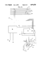
- FIG. 1 is a side elevation showing a portion of a conveyor of the invention including a load carrier for handling newsprint rolls of different sizes;
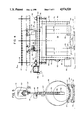
- FIG. 2 is an end elevation of the conveyor and carrier of FIG. 1;
- FIG. 3 is a schematic diagram illustrating the relation between the operational and control components of a carrier of the conveyor of FIGS. 1 and 2;
- FIG. 4 is a side elevation similar to FIG. 1 showing an alternative form of the carrier of the invention and including a transversely movable shuttle cart for receiving a newsprint roll from the carrier; and
- FIG. 5 is an end elevation of the structure shown in FIG. 4, taken as indicated by the arrows 5--5 thereon.
- the portion of a conveyor 10 of the invention shown in FIGS. 1 and 2 comprises a carrier track 12 and a load carrier 14.
- the carrier track 12 which may be of any desired length and layout (including switch-connected branch tracks), is composed of a pair of channel section track members 15 and 16 supported in toe-to-toe relation by longitudinally spaced track yokes 18 in a conventional manner.
- An electrical conductor bar assembly 20 extends along the track 12, and is supported above the track members 15 and 16 by the track yokes 18, as best shown in FIG. 2.
- the load carrier 14 includes wheeled trolleys 22 and 24 mounted on the carrier track members 15 and 16, the trolley 22 having driving means 23 powered from the conductor bar assembly 20 for propelling the load carrier along the track, the normal direction of forward carrier movement being indicated by the arrow 25 in FIG. 1.
- Carrier structure described below is supported by the trolleys 22 and 24.
- This carrier structure comprises a main frame 26 extending longitudinally of the track 12 and connected to the trolleys in vertically spaced relation below the track by supporting means 28 providing a horizontal pivoted connection 29 to each of the trolleys and vertical pivotal connections 30 to the main frame 26.
- a carrier subframe 32 positioned vertically below the main frame 26 and having load carrying means 34 secured thereto and depending therefrom for engagement with a load 36 to be transported by the carrier 14, is suspended from the main frame by power driven suspension means 38.
- the load carrying means 34 is particularly adapted for the transporting of cylindrically shaped loads 36 such as newsprint rolls which may differ in axial length.
- This load carrying means 34 is formed by a pair of load carrying arms 40, each consisting of two interconnected, longitudinally spaced members 41 secured in transversely spaced relation to transverse subframe members 42.
- the arms 40 extend downwardly from the subframe members 42 and have converging free ends 43 adapted to straddle the opposite sides of a load, each free end 43 being provided with a pivoted load engaging pad 44.
- the power driven subframe suspension means 38 comprises a reversible motor 46 mounted on the main frame 26, a longitudinally extending drive shaft 47 driven by the motor 46, and a pair of longitudinally spaced motion transmitting assemblies 48, such as jack shafts, coupled to the drive shaft 47 and to the subframe 32.
- Energization of the motor operates the assemblies 48 to move the load carrying arms 40 vertically between the raised, load supporting position 50 shown in full line in FIGS. 1 and 2 and the lowered position 51 shown in broken line. In this lowered position, a load 36 is transferable between the load carrying arms 40 and a supporting surface 52 disposed below the carrier track 12 to either deposit the load 36 on the supporting surface 52 or to pickup a load 36 thereon.
- Control means 53 mounted on the load carrier 14 and schematically illustrated in FIG. 3, automatically regulates the operation of the carrier driving motor 23, and the suspension drive motor 46 for both load pickup and load depositing operations of the load carrier 14.
- the principal components of the control means are a variable frequency motor controller 54 connected to the carrier driving motor 23 and powered from the conductor bar assembly 20, and a programmable logic controller 56 having an input section 57 and an output section 58.
- various carrier-mounted sensing elements Connected to the input section 57 are various carrier-mounted sensing elements which include a first forwardly directed banking sensor 60 responsive to the presense of a preceding load carrier for preventing overtaking engagement of the load carrier 14 therewith; a safety sensor 61 for detecting the presence of other objects in the path of travel of the load carrier 14; and load position sensing means 62 responsive to the presence of a load 36 on the supporting surface 52 for positioning the load carrier 14 along the track 12 at a desired location for the transfer of a load 36 to or from the supporting surface 52.
- the output section 58 supplies control signals to the motor controller 54 through a connector 63 and to a starter 64 for the suspension drive motor 46. As shown in FIG.
- the output section 58 is also arranged to exchange signals with a group of control bars of the conductor bar assembly for communication with a central controller for a conveyor system having a plurality of the load carriers 14 and a route network over which such carriers are dispatched. Since such communication features will vary from one conveyor system to another and are available in various forms known to persons skilled in the art, they will not be described in further detail. In general however, the communication features may include start and stop signals through a conductor bar 66, carrier position signals through a conductor bar 67, and carrier operation command and execution signals through a conductor bar group 68.
- the load position sensing means 62 are also shown in FIG. 1 and comprise a first group of elements, which will be referred to as load pickup sensors, that are adapted to position the load carrier 14 in longitudinally centered relation with a load 36 to be picked up; and, a second group of elements, which will be referred to as load detectors, that are adapted to position the load carrier 14 in a desired relation to a previously deposited load 36' on the supporting surface in order to properly transfer a load from the load carrier thereto.
- load pickup sensors that are adapted to position the load carrier 14 in longitudinally centered relation with a load 36 to be picked up
- load detectors that are adapted to position the load carrier 14 in a desired relation to a previously deposited load 36' on the supporting surface in order to properly transfer a load from the load carrier thereto.
- the load pickup sensors consist of three pairs of photocells 70, 71 and 72 arranged longitudinally of the carrier subframe 32 so that each pair of sensors is adapted to detect the opposite, longitudinally spaced ends of a load 36 of a certain length--specifically, the sensor pair 70 is spaced to detect the ends 73 of a full length newsprint roll, the sensor pair 71 the ends 74 of a 3/4 length newsprint roll and the sensor pair 72 the ends 75 of a 1/2length newsprint roll.
- a load detector is provided for each pair of sensors, namely a detector 70' for the sensor pair 70, a detector 71' for the sensor pair 71 and a detector 72' for the sensor pair 72, each of these detectors being spaced longitudinally and forwardly of its associated sensor pair a distance corresponding to the desired spacing between a previously deposited load 36' and a load to be transferred from the load carrier 14 to the supporting surface 52.
- the suspension drive motor 46 is energized to move the load carrying arms 40 to their lowered position 51, the object detector 61 is deactivated, the carrier drive motor 23 is started, and the carrier is advanced on a load 36 resting on the supporting surface 52 and held in endwise aligned relation with the carrier track 12 by suitable chocks or guides 76, as shown in FIG. 2.
- the pads 44 on the free ends of the load carrying arms 40 in their lowered position move under and into facing relation with the sides of the load 36.
- the carrier drive motor 23 is stopped.
- the controller 56 is programmed in response to these input conditions to energize the suspension drive motor 46 to move the load carrying arms 40 to the raised position 50 and activate the object detector 61.
- the carrier 14 is then operable by the carrier drive motor 23 to transport the load to any desired destination. Should that destination be one at which the transported load is to be deposited behind a previously deposited load 36' (for example, where loads are stored endwise in rows), the carrier 14 advances with the object sensor 61 inactive until the end of the load 36' is sensed by the detector 70', 71' or 72' associated with the pair of pickup sensors 70, 71 or 72 that have sensed the load being transported.
- the controller 56 responds to these input conditions by stopping the carrier drive motor 23 and energizing the suspension drive motor 46 to move the load carrying arms 40 to the lowered position 51, transferring the transported load 36 to the supporting surface 52 at a determined spaced relation to the load 36'.
- the carrier 14 is then moved forward with the load carrying arms 40 in the lowered position until any previously deposited loads have been cleared.
- the pickup operation described above is performed on the load at the head end of a line of such loads, the carrier being advanced along the line with its load carrying arms 40 in their lowered position until no preceding load is detected.
- FIGS. 4 and 5 illustrate an alternative form of load carrier 14' which employs basically the same components as the carrier 14 (identified by the same reference numbers), but which is adapted to transfer a load 36 between load carrying means 34' of the carrier and a supporting surface 52' provided on a shuttle cart 78 mounted on wheels 79 for movement in a direction transverse to the conveyor track 12.
- the load carrying means 34' comprises a pair of load supports 80, each consisting of a support member 82 having one end secured to the carrier subframe 32 and extending vertically downwardly therefrom to a cradle formed by a transverse member 84 and a pair of parallel, longitudinally extending, transversely spaced load engaging members 85.
- the cradle member 85 of one of the pair of load supports 80 as shown in FIG. 4, project toward the cradle members 85 of the other load support 80 of the pair a distance such that full, three-quarters and one-half size newsprint rolls can be handled.
- This alternative load carrier 14' may be provided with a manual push button control 86 for enabling the carrier to be properly positioned relative to the shuttle cart 78 for a load transfer operation, and may also be provided with a safety bumper 88 operable to stop the carrier driving motor 23 on contact with an object.
- the carrier 14' For a pickup operation, the carrier 14' is moved into a longitudinally centered relation with the path of transverse movement of the shuttle cart 78. With the carrier load supports 80 in their lowered position 51, the shuttle cart 78 is shifted into aligned position with the carrier and the suspension drive motor 46 is energized, moving the load supports 80 to their raised position 50.
- a load depositing operation is the reverse except that an empty shuttle cart 78 may be prepositioned in load receiving relation with the carrier 14'.
Landscapes
- Engineering & Computer Science (AREA)
- Transportation (AREA)
- Mechanical Engineering (AREA)
- Chain Conveyers (AREA)
- Load-Engaging Elements For Cranes (AREA)
- Carriers, Traveling Bodies, And Overhead Traveling Cranes (AREA)
Abstract
Description
Claims (14)
Priority Applications (3)
| Application Number | Priority Date | Filing Date | Title |
|---|---|---|---|
| US07/341,586 US4974520A (en) | 1989-04-21 | 1989-04-21 | Conveyor with self-loading and unloading carriers |
| AU52222/90A AU637088B2 (en) | 1989-04-21 | 1990-03-26 | Conveyor with self-loading and unloading carriers |
| JP02091344A JP3102566B2 (en) | 1989-04-21 | 1990-04-04 | Conveyor with self-loading and unloading carrier |
Applications Claiming Priority (1)
| Application Number | Priority Date | Filing Date | Title |
|---|---|---|---|
| US07/341,586 US4974520A (en) | 1989-04-21 | 1989-04-21 | Conveyor with self-loading and unloading carriers |
Publications (1)
| Publication Number | Publication Date |
|---|---|
| US4974520A true US4974520A (en) | 1990-12-04 |
Family
ID=23338181
Family Applications (1)
| Application Number | Title | Priority Date | Filing Date |
|---|---|---|---|
| US07/341,586 Expired - Lifetime US4974520A (en) | 1989-04-21 | 1989-04-21 | Conveyor with self-loading and unloading carriers |
Country Status (3)
| Country | Link |
|---|---|
| US (1) | US4974520A (en) |
| JP (1) | JP3102566B2 (en) |
| AU (1) | AU637088B2 (en) |
Cited By (14)
| Publication number | Priority date | Publication date | Assignee | Title |
|---|---|---|---|---|
| WO1995014599A1 (en) * | 1993-11-24 | 1995-06-01 | Telelift Gmbh | Rail mounted transport system |
| EP0693409A1 (en) * | 1994-07-20 | 1996-01-24 | Ve.Ma.C. S.R.L. | Apparatus for transferring loads |
| WO1996031381A1 (en) * | 1995-04-03 | 1996-10-10 | Cegelec Aeg Anlagen-Und Automatisierungstechnik Gmbh | Track-guided transport system with power and data transmission |
| US20030185660A1 (en) * | 2000-03-06 | 2003-10-02 | Kafka Alfred J. | Apparatus for transport and delivery of articles |
| US20060186259A1 (en) * | 2005-02-22 | 2006-08-24 | Man Roland Druckmaschinen Ag | Reel changer of a web-fed printing press |
| US7192236B1 (en) * | 1999-03-02 | 2007-03-20 | Westfalia-Wst-Systemtechnik Gmbh & Co. Kg | Shelf stacking machine |
| US20070225858A1 (en) * | 2006-03-24 | 2007-09-27 | Lauyans & Company | Control system for a pallet load transport system |
| US20090263215A1 (en) * | 2008-04-18 | 2009-10-22 | Applied Materials, Inc. | End effector for a cluster tool |
| US20100005710A1 (en) * | 2008-07-09 | 2010-01-14 | Pipal Energy Resources, Llc | Upgrading Carbonaceous Materials |
| EP2996922A4 (en) * | 2013-05-16 | 2017-02-15 | Futran Ltd | A rail transport bogie and a rail transportation system |
| CN109677510A (en) * | 2018-11-05 | 2019-04-26 | 浦生(上海)工业自动化设备有限公司 | A kind of assembly line transport vehicle headstock and its application method |
| US10604350B1 (en) * | 2014-10-27 | 2020-03-31 | Surface Combustion, Inc. | System for controlling torque-limiting drive charge car |
| US20210188560A1 (en) * | 2018-04-06 | 2021-06-24 | Sst Systems, Inc. | Conveyor system with automated carriers |
| CN115848928A (en) * | 2023-02-15 | 2023-03-28 | 安徽中科晶格技术有限公司 | Automatic access scanning device and method |
Families Citing this family (1)
| Publication number | Priority date | Publication date | Assignee | Title |
|---|---|---|---|---|
| JP6291532B2 (en) * | 2016-07-13 | 2018-03-14 | 本田技研工業株式会社 | Engagement confirmation method by robot |
Citations (19)
| Publication number | Priority date | Publication date | Assignee | Title |
|---|---|---|---|---|
| US1155760A (en) * | 1913-03-25 | 1915-10-05 | Gustaf Sauvola | Elevated railway. |
| DE518644C (en) * | 1928-12-30 | 1931-02-20 | Arthur H Mueller Dipl Ing | Procedure on overhead railways for picking up and setting down load containers through moving hangars |
| DE520463C (en) * | 1928-12-29 | 1931-03-11 | Adolf Bleichert & Co A G | Device for the automatic loading and unloading of cable car cars on hanging railways |
| US2924484A (en) * | 1955-04-04 | 1960-02-09 | William A Tolsma | Drum grabs |
| US3180279A (en) * | 1962-12-05 | 1965-04-27 | Thibault Paul | Overhead conveyor system |
| US3237980A (en) * | 1964-04-06 | 1966-03-01 | Country Engineering Inc | Cylindrical object clamping devices |
| SU501911A1 (en) * | 1972-10-16 | 1976-02-05 | Предприятие П/Я Г-4617 | Trailer mounted monorail |
| DE2756600A1 (en) * | 1977-12-19 | 1979-07-05 | Ruhrthaler Maschinenfabrik Sch | Monorail suspension conveyor track - has trolley and hoist units with universal joint shaft transmission connections |
| JPS54120178A (en) * | 1978-03-08 | 1979-09-18 | Daifuku Co Ltd | Method of and apparatus for turning cargo suspending arms of hanger employed in trolley conveyor |
| US4341161A (en) * | 1980-05-08 | 1982-07-27 | Honda Giken Kogyo Kabushiki Kaisha | Workpiece hanger carriage |
| JPS5927979A (en) * | 1981-12-21 | 1984-02-14 | Kao Corp | Refrigerant additives and refrigerant compositions |
| US4462315A (en) * | 1980-11-28 | 1984-07-31 | Nakanishi Metal Works Co., Ltd. | Power-and-free trolley conveyor |
| US4464998A (en) * | 1982-03-25 | 1984-08-14 | Nakanishi Metal Works Co., Ltd. | Hanger device for trolley conveyor |
| US4475462A (en) * | 1981-03-19 | 1984-10-09 | Nissan Motor Company, Limited | Tiltable hanger apparatus |
| DE3432284A1 (en) * | 1984-09-01 | 1986-03-13 | Clemens-A. Dipl.-Ing. 5600 Wuppertal Verbeek | Rail transport system with a travelling carriage arranged at a distance from the storage plane |
| US4750132A (en) * | 1985-09-19 | 1988-06-07 | Giorgio Pessina | Automatic signature pack transfer apparatus |
| US4770106A (en) * | 1986-01-20 | 1988-09-13 | Mannesmann Ag | Rail vehicle |
| DE3710436A1 (en) * | 1987-03-28 | 1988-10-13 | Gutehoffnungshuette Man | Trolley of a crane for either grab or packaged-goods operation |
| US4863335A (en) * | 1988-03-25 | 1989-09-05 | Haines & Emerson, Inc. | Automatic guided vehicle roll-handling system |
-
1989
- 1989-04-21 US US07/341,586 patent/US4974520A/en not_active Expired - Lifetime
-
1990
- 1990-03-26 AU AU52222/90A patent/AU637088B2/en not_active Ceased
- 1990-04-04 JP JP02091344A patent/JP3102566B2/en not_active Expired - Fee Related
Patent Citations (19)
| Publication number | Priority date | Publication date | Assignee | Title |
|---|---|---|---|---|
| US1155760A (en) * | 1913-03-25 | 1915-10-05 | Gustaf Sauvola | Elevated railway. |
| DE520463C (en) * | 1928-12-29 | 1931-03-11 | Adolf Bleichert & Co A G | Device for the automatic loading and unloading of cable car cars on hanging railways |
| DE518644C (en) * | 1928-12-30 | 1931-02-20 | Arthur H Mueller Dipl Ing | Procedure on overhead railways for picking up and setting down load containers through moving hangars |
| US2924484A (en) * | 1955-04-04 | 1960-02-09 | William A Tolsma | Drum grabs |
| US3180279A (en) * | 1962-12-05 | 1965-04-27 | Thibault Paul | Overhead conveyor system |
| US3237980A (en) * | 1964-04-06 | 1966-03-01 | Country Engineering Inc | Cylindrical object clamping devices |
| SU501911A1 (en) * | 1972-10-16 | 1976-02-05 | Предприятие П/Я Г-4617 | Trailer mounted monorail |
| DE2756600A1 (en) * | 1977-12-19 | 1979-07-05 | Ruhrthaler Maschinenfabrik Sch | Monorail suspension conveyor track - has trolley and hoist units with universal joint shaft transmission connections |
| JPS54120178A (en) * | 1978-03-08 | 1979-09-18 | Daifuku Co Ltd | Method of and apparatus for turning cargo suspending arms of hanger employed in trolley conveyor |
| US4341161A (en) * | 1980-05-08 | 1982-07-27 | Honda Giken Kogyo Kabushiki Kaisha | Workpiece hanger carriage |
| US4462315A (en) * | 1980-11-28 | 1984-07-31 | Nakanishi Metal Works Co., Ltd. | Power-and-free trolley conveyor |
| US4475462A (en) * | 1981-03-19 | 1984-10-09 | Nissan Motor Company, Limited | Tiltable hanger apparatus |
| JPS5927979A (en) * | 1981-12-21 | 1984-02-14 | Kao Corp | Refrigerant additives and refrigerant compositions |
| US4464998A (en) * | 1982-03-25 | 1984-08-14 | Nakanishi Metal Works Co., Ltd. | Hanger device for trolley conveyor |
| DE3432284A1 (en) * | 1984-09-01 | 1986-03-13 | Clemens-A. Dipl.-Ing. 5600 Wuppertal Verbeek | Rail transport system with a travelling carriage arranged at a distance from the storage plane |
| US4750132A (en) * | 1985-09-19 | 1988-06-07 | Giorgio Pessina | Automatic signature pack transfer apparatus |
| US4770106A (en) * | 1986-01-20 | 1988-09-13 | Mannesmann Ag | Rail vehicle |
| DE3710436A1 (en) * | 1987-03-28 | 1988-10-13 | Gutehoffnungshuette Man | Trolley of a crane for either grab or packaged-goods operation |
| US4863335A (en) * | 1988-03-25 | 1989-09-05 | Haines & Emerson, Inc. | Automatic guided vehicle roll-handling system |
Cited By (25)
| Publication number | Priority date | Publication date | Assignee | Title |
|---|---|---|---|---|
| WO1995014599A1 (en) * | 1993-11-24 | 1995-06-01 | Telelift Gmbh | Rail mounted transport system |
| US5735217A (en) * | 1993-11-24 | 1998-04-07 | Telelift Gmbh | Rail-type conveyor system |
| EP0693409A1 (en) * | 1994-07-20 | 1996-01-24 | Ve.Ma.C. S.R.L. | Apparatus for transferring loads |
| WO1996031381A1 (en) * | 1995-04-03 | 1996-10-10 | Cegelec Aeg Anlagen-Und Automatisierungstechnik Gmbh | Track-guided transport system with power and data transmission |
| AU696180B2 (en) * | 1995-04-03 | 1998-09-03 | Cegelec Aeg Anlagen- Und Automatisierungstechnik Gmbh | Track-guided transport system with power and data transmission |
| US6089512A (en) * | 1995-04-03 | 2000-07-18 | Daimler-Benz Aktiengesellschaft | Track-guided transport system with power and data transmission |
| CN1076292C (en) * | 1995-04-03 | 2001-12-19 | 戴姆勒-奔驰公司 | Track-guided transport system with power and data transmission |
| US7192236B1 (en) * | 1999-03-02 | 2007-03-20 | Westfalia-Wst-Systemtechnik Gmbh & Co. Kg | Shelf stacking machine |
| US20030185660A1 (en) * | 2000-03-06 | 2003-10-02 | Kafka Alfred J. | Apparatus for transport and delivery of articles |
| US7011487B2 (en) | 2000-03-06 | 2006-03-14 | Jervis B. Webb Company | Apparatus for transport and delivery of articles |
| US20060186259A1 (en) * | 2005-02-22 | 2006-08-24 | Man Roland Druckmaschinen Ag | Reel changer of a web-fed printing press |
| US20070225858A1 (en) * | 2006-03-24 | 2007-09-27 | Lauyans & Company | Control system for a pallet load transport system |
| US20090263215A1 (en) * | 2008-04-18 | 2009-10-22 | Applied Materials, Inc. | End effector for a cluster tool |
| US8322963B2 (en) * | 2008-04-18 | 2012-12-04 | Applied Materials, Inc. | End effector for a cluster tool |
| US20100005710A1 (en) * | 2008-07-09 | 2010-01-14 | Pipal Energy Resources, Llc | Upgrading Carbonaceous Materials |
| US8021445B2 (en) | 2008-07-09 | 2011-09-20 | Skye Energy Holdings, Inc. | Upgrading carbonaceous materials |
| US8778036B2 (en) | 2008-07-09 | 2014-07-15 | Skye Energy Holdings, Inc. | Upgrading carbonaceous materials |
| EP2996922A4 (en) * | 2013-05-16 | 2017-02-15 | Futran Ltd | A rail transport bogie and a rail transportation system |
| US10604350B1 (en) * | 2014-10-27 | 2020-03-31 | Surface Combustion, Inc. | System for controlling torque-limiting drive charge car |
| US20210188560A1 (en) * | 2018-04-06 | 2021-06-24 | Sst Systems, Inc. | Conveyor system with automated carriers |
| US11738951B2 (en) * | 2018-04-06 | 2023-08-29 | Sst Systems, Inc. | Conveyor system with automated carriers |
| CN109677510A (en) * | 2018-11-05 | 2019-04-26 | 浦生(上海)工业自动化设备有限公司 | A kind of assembly line transport vehicle headstock and its application method |
| CN109677510B (en) * | 2018-11-05 | 2024-01-26 | 浦生(上海)工业自动化设备有限公司 | Assembly line transport vehicle head and application method thereof |
| CN115848928A (en) * | 2023-02-15 | 2023-03-28 | 安徽中科晶格技术有限公司 | Automatic access scanning device and method |
| CN115848928B (en) * | 2023-02-15 | 2023-05-16 | 安徽中科晶格技术有限公司 | Automatic access scanning device and method |
Also Published As
| Publication number | Publication date |
|---|---|
| JP3102566B2 (en) | 2000-10-23 |
| AU5222290A (en) | 1990-10-25 |
| AU637088B2 (en) | 1993-05-20 |
| JPH02293251A (en) | 1990-12-04 |
Similar Documents
| Publication | Publication Date | Title |
|---|---|---|
| US4974520A (en) | Conveyor with self-loading and unloading carriers | |
| JP3466195B2 (en) | Selective delivery conveyor system | |
| US10829320B2 (en) | Conveyor system for the conveying of goods items | |
| US3817406A (en) | Automatic storage system with stacker cranes and load handling dollies | |
| KR960005533B1 (en) | Load transport system for automated warehousing | |
| US20040109746A1 (en) | Overhead travelling carriage system | |
| US7178660B2 (en) | Workpiece transport system with independently driven platforms | |
| US4548135A (en) | Floor conveyor system | |
| JP5626579B2 (en) | Article conveying apparatus and article-conveying moving body provided with the same | |
| CA2653167A1 (en) | Workpiece transportation system comprising automated transport vehicles and workpiece carriers | |
| JP2004115000A (en) | Conveyance system of paper reel, conveyance method, and transport device | |
| KR20220081084A (en) | Automatic cargo transportation apparatus | |
| US20060060446A1 (en) | System with stationary and mobile functional devices | |
| US6279306B1 (en) | Operator controlled spinning can transporter | |
| US5729868A (en) | Can storage device for rectangular cans at a can filling station | |
| US20060072990A1 (en) | Device for distributing unit load freight carriers | |
| JP3611087B2 (en) | Goods storage facility | |
| US5127788A (en) | System for transporting bobbins between spinning machines | |
| JPH0344974B2 (en) | ||
| JPH032107B2 (en) | ||
| JP2002145407A (en) | Carry-in system for automated storage and retrieval warehouse installation | |
| JP4862359B2 (en) | Traveling control system for traveling body and traveling control method for traveling body | |
| JPH0228401A (en) | Article transport arrangement | |
| JPH04333404A (en) | Cargo handling device | |
| JP2748094B2 (en) | Movable partition panel loading / unloading device |
Legal Events
| Date | Code | Title | Description |
|---|---|---|---|
| AS | Assignment |
Owner name: JERVIS B. WEBB COMPANY, MICHIGAN Free format text: ASSIGNMENT OF ASSIGNORS INTEREST.;ASSIGNOR:DEHNE, CLARENCE A.;REEL/FRAME:005094/0494 Effective date: 19890530 |
|
| STCF | Information on status: patent grant |
Free format text: PATENTED CASE |
|
| FPAY | Fee payment |
Year of fee payment: 4 |
|
| FEPP | Fee payment procedure |
Free format text: PAYOR NUMBER ASSIGNED (ORIGINAL EVENT CODE: ASPN); ENTITY STATUS OF PATENT OWNER: LARGE ENTITY |
|
| FPAY | Fee payment |
Year of fee payment: 8 |
|
| FEPP | Fee payment procedure |
Free format text: PAYER NUMBER DE-ASSIGNED (ORIGINAL EVENT CODE: RMPN); ENTITY STATUS OF PATENT OWNER: LARGE ENTITY Free format text: PAYOR NUMBER ASSIGNED (ORIGINAL EVENT CODE: ASPN); ENTITY STATUS OF PATENT OWNER: LARGE ENTITY |
|
| FPAY | Fee payment |
Year of fee payment: 12 |
|
| AS | Assignment |
Owner name: CONGRESS FINANCIAL CORPORATION (CENTRAL), ILLINOIS Free format text: SECURITY AGREEMENT;ASSIGNOR:JERVIS B. WEBB COMPANY;REEL/FRAME:014484/0094 Effective date: 20040319 |
|
| AS | Assignment |
Owner name: JERVIS B. WEBB COMPANY, MICHIGAN Free format text: RELEASE BY SECURED PARTY;ASSIGNOR:WACHOVIA CAPITAL FINANCE CORPORATION (CENTRAL) F/K/A CONGRESS FINANCIAL CORPORATION (CENTRAL);REEL/FRAME:020995/0318 Effective date: 20080409 |