US4918921A - Coaxial push rod and hollow screw ball nut drive for master cylinder - Google Patents
Coaxial push rod and hollow screw ball nut drive for master cylinder Download PDFInfo
- Publication number
- US4918921A US4918921A US07/111,294 US11129487A US4918921A US 4918921 A US4918921 A US 4918921A US 11129487 A US11129487 A US 11129487A US 4918921 A US4918921 A US 4918921A
- Authority
- US
- United States
- Prior art keywords
- bore
- master cylinder
- motor
- push rod
- armature
- Prior art date
- Legal status (The legal status is an assumption and is not a legal conclusion. Google has not performed a legal analysis and makes no representation as to the accuracy of the status listed.)
- Expired - Lifetime
Links
Images


Classifications
-
- F—MECHANICAL ENGINEERING; LIGHTING; HEATING; WEAPONS; BLASTING
- F16—ENGINEERING ELEMENTS AND UNITS; GENERAL MEASURES FOR PRODUCING AND MAINTAINING EFFECTIVE FUNCTIONING OF MACHINES OR INSTALLATIONS; THERMAL INSULATION IN GENERAL
- F16D—COUPLINGS FOR TRANSMITTING ROTATION; CLUTCHES; BRAKES
- F16D48/00—External control of clutches
- F16D48/02—Control by fluid pressure
- F16D48/04—Control by fluid pressure providing power assistance
-
- B—PERFORMING OPERATIONS; TRANSPORTING
- B60—VEHICLES IN GENERAL
- B60T—VEHICLE BRAKE CONTROL SYSTEMS OR PARTS THEREOF; BRAKE CONTROL SYSTEMS OR PARTS THEREOF, IN GENERAL; ARRANGEMENT OF BRAKING ELEMENTS ON VEHICLES IN GENERAL; PORTABLE DEVICES FOR PREVENTING UNWANTED MOVEMENT OF VEHICLES; VEHICLE MODIFICATIONS TO FACILITATE COOLING OF BRAKES
- B60T13/00—Transmitting braking action from initiating means to ultimate brake actuator with power assistance or drive; Brake systems incorporating such transmitting means, e.g. air-pressure brake systems
- B60T13/74—Transmitting braking action from initiating means to ultimate brake actuator with power assistance or drive; Brake systems incorporating such transmitting means, e.g. air-pressure brake systems with electrical assistance or drive
- B60T13/745—Transmitting braking action from initiating means to ultimate brake actuator with power assistance or drive; Brake systems incorporating such transmitting means, e.g. air-pressure brake systems with electrical assistance or drive acting on a hydraulic system, e.g. a master cylinder
-
- F—MECHANICAL ENGINEERING; LIGHTING; HEATING; WEAPONS; BLASTING
- F16—ENGINEERING ELEMENTS AND UNITS; GENERAL MEASURES FOR PRODUCING AND MAINTAINING EFFECTIVE FUNCTIONING OF MACHINES OR INSTALLATIONS; THERMAL INSULATION IN GENERAL
- F16D—COUPLINGS FOR TRANSMITTING ROTATION; CLUTCHES; BRAKES
- F16D48/00—External control of clutches
- F16D48/02—Control by fluid pressure
- F16D2048/0212—Details of pistons for primary or secondary cylinders especially adapted for fluid control
-
- F—MECHANICAL ENGINEERING; LIGHTING; HEATING; WEAPONS; BLASTING
- F16—ENGINEERING ELEMENTS AND UNITS; GENERAL MEASURES FOR PRODUCING AND MAINTAINING EFFECTIVE FUNCTIONING OF MACHINES OR INSTALLATIONS; THERMAL INSULATION IN GENERAL
- F16D—COUPLINGS FOR TRANSMITTING ROTATION; CLUTCHES; BRAKES
- F16D2125/00—Components of actuators
- F16D2125/02—Fluid-pressure mechanisms
- F16D2125/10—Plural pistons interacting by fluid pressure, e.g. hydraulic force amplifiers using different sized pistons
-
- F—MECHANICAL ENGINEERING; LIGHTING; HEATING; WEAPONS; BLASTING
- F16—ENGINEERING ELEMENTS AND UNITS; GENERAL MEASURES FOR PRODUCING AND MAINTAINING EFFECTIVE FUNCTIONING OF MACHINES OR INSTALLATIONS; THERMAL INSULATION IN GENERAL
- F16D—COUPLINGS FOR TRANSMITTING ROTATION; CLUTCHES; BRAKES
- F16D2125/00—Components of actuators
- F16D2125/18—Mechanical mechanisms
- F16D2125/20—Mechanical mechanisms converting rotation to linear movement or vice versa
- F16D2125/34—Mechanical mechanisms converting rotation to linear movement or vice versa acting in the direction of the axis of rotation
- F16D2125/40—Screw-and-nut
-
- F—MECHANICAL ENGINEERING; LIGHTING; HEATING; WEAPONS; BLASTING
- F16—ENGINEERING ELEMENTS AND UNITS; GENERAL MEASURES FOR PRODUCING AND MAINTAINING EFFECTIVE FUNCTIONING OF MACHINES OR INSTALLATIONS; THERMAL INSULATION IN GENERAL
- F16D—COUPLINGS FOR TRANSMITTING ROTATION; CLUTCHES; BRAKES
- F16D2500/00—External control of clutches by electric or electronic means
- F16D2500/10—System to be controlled
- F16D2500/102—Actuator
- F16D2500/1021—Electrical type
- F16D2500/1023—Electric motor
- F16D2500/1024—Electric motor combined with hydraulic actuation
-
- F—MECHANICAL ENGINEERING; LIGHTING; HEATING; WEAPONS; BLASTING
- F16—ENGINEERING ELEMENTS AND UNITS; GENERAL MEASURES FOR PRODUCING AND MAINTAINING EFFECTIVE FUNCTIONING OF MACHINES OR INSTALLATIONS; THERMAL INSULATION IN GENERAL
- F16D—COUPLINGS FOR TRANSMITTING ROTATION; CLUTCHES; BRAKES
- F16D2500/00—External control of clutches by electric or electronic means
- F16D2500/30—Signal inputs
- F16D2500/302—Signal inputs from the actuator
- F16D2500/3026—Stroke
-
- F—MECHANICAL ENGINEERING; LIGHTING; HEATING; WEAPONS; BLASTING
- F16—ENGINEERING ELEMENTS AND UNITS; GENERAL MEASURES FOR PRODUCING AND MAINTAINING EFFECTIVE FUNCTIONING OF MACHINES OR INSTALLATIONS; THERMAL INSULATION IN GENERAL
- F16D—COUPLINGS FOR TRANSMITTING ROTATION; CLUTCHES; BRAKES
- F16D2500/00—External control of clutches by electric or electronic means
- F16D2500/50—Problem to be solved by the control system
- F16D2500/51—Relating safety
- F16D2500/5114—Failsafe
-
- Y—GENERAL TAGGING OF NEW TECHNOLOGICAL DEVELOPMENTS; GENERAL TAGGING OF CROSS-SECTIONAL TECHNOLOGIES SPANNING OVER SEVERAL SECTIONS OF THE IPC; TECHNICAL SUBJECTS COVERED BY FORMER USPC CROSS-REFERENCE ART COLLECTIONS [XRACs] AND DIGESTS
- Y10—TECHNICAL SUBJECTS COVERED BY FORMER USPC
- Y10T—TECHNICAL SUBJECTS COVERED BY FORMER US CLASSIFICATION
- Y10T74/00—Machine element or mechanism
- Y10T74/19—Gearing
- Y10T74/19535—Follow-up mechanism
Definitions
- This invention relates to master cylinder assemblies and more particularly to a master cylinder assembly in which the master cylinder is actuated by an electric motor forming a part of the master cylinder assembly.
- Master cylinders are in wide use in various industries, but particularly in the motor vehicle industry wherein they serve in conjunction with an associated slave cylinder to control various systems of the motor vehicle.
- the brakes of a motor vehicle are typically actuated by slave cylinders located at the wheels of the vehicle and supplied with pressure fluid from a master cylinder actuated by the brake pedal of the vehicle.
- the clutches of manual transmission vehicles are often engaged and disengaged by a slave cylinder located at the clutch assembly and receiving pressure fluid from a master cylinder actuated by a clutch pedal of the vehicle.
- the master cylinder is directly and manually actuated by the vehicle operator by suitable actuation of the associated control pedal of the vehicle.
- This invention is directed to the provision of an improved master cylinder assembly.
- this invention is directed to the provision of a power operated master cylinder assembly especially suitable for use in engaging and disengaging the clutch of a manual transmission motor vehicle.
- the master cylinder assembly of the invention comprises a motor including a housing; a hydraulic master cylinder including a housing rigid with the motor housing, a cylinder defining an elongated bore, a piston movable linearly and slidably in the bore, inlet means in the cylinder for admitting hydraulic fluid into the bore from a reservoir and an outlet fitting in the cylinder communicating with the bore and operative to convey hydraulic fluid out of the bore for delivery to a slave device in response to linear movement of the piston in the bore; and means operative in response to actuation of the motor to move the piston linearly in the bore.
- This arrangement provides a simple and compact drive mechanism especially suitable for any situation requiring a power operated master cylinder.
- the motor is an electric motor and the operative means comprises drive means operative in response to energization of the motor to move the piston linearly in the bore of the master cylinder.
- the motor further includes an armature, nut means driven by and associated with the armature, and an output shaft having a threaded portion threadably engaging the nut means so that rotation of the armature upon energization of the motor linearly advances the output shaft; and the drive means is operative to move the piston linearly in the bore of the hydraulic cylinder in response to linear advancement of the motor output shaft.
- the nut means comprises a ball nut
- the output shaft threaded portion comprises a ball screw
- the master cylinder assembly further includes bearing balls circulating in the races coactingly formed between the grooves of the ball screw and the grooves of the ball nut and ball guide return means to provide ball recirculation.
- the motor output shaft is mounted for rotation in the motor housing about an axis that is coaxial with the axis of the bore of the master cylinder.
- the motor output shaft is drivingly and coaxially coupled to the piston of the master cylinder.
- This arrangement provides a direct and efficient means of transferring the linear movement of the motor output shaft to the linear movement of the master cylinder piston.
- the invention also provides a novel control system for a motor vehicle.
- the motor vehicle control system includes a hydraulic master cylinder assembly including a cylinder defining a bore, a piston mounted for linear movement in the bore, and an outlet fitting communicating with the bore; a hydraulic slave cylinder having an inlet fitting; a hydraulic conduit interconnecting the outlet fitting of the master cylinder and the inlet fitting of the slave cylinder; an electric motor; and means operative in response to energization of the motor to move the piston linearly in the bore of the master cylinder to eject hydraulic fluid from the outlet fitting of the master cylinder for delivery to the slave cylinder.
- This arrangement provides a compact and efficient control system for controlling the operation of a motor vehicle system or assembly.
- the slave cylinder constitutes the actuating mechanism for the vehicle clutch assembly.
- the slave cylinder constitutes the actuating mechanism for the vehicle brake system.
- control system further includes control means operative to energize the motor in response to a predetermined movement of a vehicle control member.
- control member is the clutch pedal of the vehicle;
- slave cylinder comprises the actuating mechanism for the vehicle clutch; and
- the control means is operative in response to operator depression of the clutch pedal to energize the motor in a sense to move the piston linearly in the bore of the master cylinder in a direction to deliver hydraulic fluid to the slave cylinder to disengage the clutch.
- control member is the brake pedal of the vehicle;
- slave cylinder comprises the actuating mechanism for the vehicle brake system; and
- control means is operative in response to operator depression of the brake pedal to energize the motor in a sense to move the piston linearly in the bore of the master cylinder in a direction to deliver hydraulic fluid to the slave cylinder to actuate the vehicle brake system.
- control member is the gearshift lever of the vehicle;
- slave cylinder comprises the actuating mechanism for the vehicle clutch assembly; and
- control means is operative in response to operator movement of the gearshift lever to energize the motor in a sense to move the piston lineary in the bore of the master cylinder in a direction to deliver hydraulic fluid to the slave cylinder to disengage the clutch assembly.
- the invention is also directed to a unique electric motor comprising a housing; an armature mounted for rotation in the housing; a ball nut mounted for rotation with the armature; a ball screw threadably engaging the ball nut; and ball guide return means to provide ball recirculation.
- This arrangement provides a highly efficient electric motor mechanism for producing linear movement in response to energization of the motor.
- the armature of the electric motor is annular and the ball nut is positioned concentrically within the armature. This arrangement provides an extremely compact and efficient package.
- the ball screw is annular and defines a bore extending axially therethrough and the motor further includes a push rod slidably received in the ball screw bore and projecting out of one end of the ball screw bore and one way drive means between the push rod and the ball screw.
- This arrangement is especially suitable for use in a vehicle braking system since it allows a further override push rod, connected to the brake pedal of the vehicle, to extend into the other end of the ball screw bore to manually move the first push rod in the event of a failure of the motor to move the push rod in response to operator depression of the brake pedal.
- FIG. 1 is a cross-sectional view of the master cylinder assembly of the invention
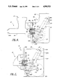
- FIG. 2 is a cross-sectional view taken on line 2--2 of FIG. 1;
- FIGS. 3 and 4 are detailed views showing a ball screw drive mechanism employed in the invention master cylinder assembly
- FIG. 5 is a view of an adapter plate employed in the invention master cylinder assembly
- FIG. 6 is a view of a modified version of the invention master cylinder assembly
- FIG. 7 is a view of a further modified version of the invention master cylinder assembly
- FIG. 8 is a schematic view of a clutch control system employing a master cylinder assembly according to the invention.
- FIG. 9 is a schematic view of a further clutch control system employing a master cylinder assembly according to the invention.
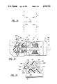
- FIG. 10 is a cross-sectional view of a master cylinder assembly according to the invention especially suitable for use in a vehicle braking system;
- FIG. 11 is a view of a motor vehicle brake control system employing the master cylinder assembly of FIG. 10;
- FIG. 12 is a view of a further modified version of the invention master cylinder assembly
- FIG. 13 is a detailed view on an enlarged scale of a portion of the master cylinder assembly of FIG. 12;
- FIG. 14 is a detailed view of a motor control circuit usable in any of the disclosed master cylinder assemblies.
- the master cylinder assembly 10 seen in FIGS. 1-5 broadly considered, includes, an electric motor 11 and a master cylinder 12 interconnected by an adapter plate 14.
- Motor 11 is of the direct current permanent magnet design and includes an annular main body housing 16, a rearward end cap 18, a forward end cap 20, an auxiliary rearward end cap 21, an auxiliary forward end cap 22, a pair of permanent magnets 24, an armature assembly 26, and a ball screw assembly 28.
- Main body annular housing 16 is formed of a suitable ferrous material and is clamped between end caps 18 and 20 by through blots 30 passing through apertures in end cap 20 for threaded engagement with tapped bores in end cap 18 so as to clamp main body housing 16 between end caps 18 and 20.
- End cap 20 is annular to define a central opening 20a and end cap 18 includes a central hub portion 18a defining a central aperture 18b receiving a ball bearing 32.
- Auxiliary rearward end cap 21 is cup-shaped and is rigidly secured to the rear face of end cap 18 by suitable fastener members (not shown) to define a cavity 34 between end cap 18 and auxiliary end cap 21.
- Auxiliary end cap 21 further includes a central aperture 21a of generally circular cross section with a flatted side.
- Auxiliary end cap 22 is cup-shaped and is suitably rigidly secured to end cap 20 by fastener means (not shown) to define a chamber 36 between auxiliary end cap 22 and end cap 20.
- Auxiliary end cap 22 further includes a central aperture 22a receiving a ball bearing 38.
- permanent magnets 24 are arcuate and are positioned on the interior circumferential surface of housing 16 with gaps 24a and 24b therebetween for passage of bolts 30.
- Armature assembly 26 includes an armature 40, a commutator 42, a position sensor 44, a journal shaft portion 46, laminations 48, and windings 50.
- Armature 40 includes a tubular main body portion 40a, and an enlarged diameter tubular forward end portion 40b interconnected to main body portion 40a by annular shoulder 40c.
- Commutator 42 is of known form and is rigidly secured to the rear end of armature main body portion 40a.
- Position sensor 44 is of disk configuration, is positioned within cavity 34, and is rigidly interconnected to commutator 42 by armature journal portion 46.
- Enlarged armature tubular end portion 40b is received in bearing 38 and armature journal shaft portion 46 is received in bearing 32 so as to mount armature 40 for rotation about central lengthwise motor axis 52.
- Laminations 48 are secured in face to face relation on armature main body portion 40a and include spoke portions 48a defining gaps 48b therebetween. Windings 50 are wound in known manner around laminations 48 and through gaps 48b and are interconnected to commutator 42 in known manner.
- Commutator 42 in turn coacts with brushes 54 carried by end cap 18. Brushes 54 provide electrical power to the commutator and thereby to the motor in known manner so that the armature assembly is caused to rotate about central axis 52.
- Ball screw assembly 28 includes a ball nut 56 and a ball screw 58.
- Ball nut 56 is fixedly mounted in enlarged armature tubular forward end portion 40b and includes, in known manner, a helical precision ground ball groove 56a.
- Ball screw 58 includes a main body portion 58a positioned within armature tubular main body portion 40a, a rearward extension portion 58b, a ball groove portion 58c, and a forward input rod portion 58d.
- Groove portion 58c coacts with grooves 56a of ball nut 56 to define ball races, and bearing balls 60 circulate in known manner in the races to provide linear movement of ball screw 58 in response to rotation of armature assembly 26.
- Ball screw assembly 28 may be of any known type but preferably is of the internal ball return type wherein, after each turn, the balls are fed back to the preceding turn by a floating liner situated inside the nut.
- Extension portion 58b of the ball screw passes slidably through aligned bores in commutator 42, armature shaft journal portion 46, and position sensor 44 and through central aperture 21a of auxiliary end cap 21 to position the extreme end of the extension portion outside of auxiliary end cap 21 and within a protective cup-shaped cap 62 suitably secured to auxiliary end cap 21.
- Shaft extension 58b includes a flatted side for coaction with the flatted side of aperture 21a so as to preclude rotation of ball screw 58 upon rotation of armature assembly 26.
- Master cylinder 12 includes a main body member 64, a reservoir 66, a flange 68, a piston 70, a sleeve 71, and a return spring 72.
- Main body member 64, reservoir 66 and flange 68 are formed as a single piece integrally molded plastic member.
- Threaded metal studs 76 extend axially rearwardly from flange 68 in circumferentially spaced relation.
- Main body member 64 defines an elongated axial bore 64a and sleeve 71 is positioned in bore 64a to define an elongated cylindrical bore 71a.
- Sleeve 71 is metallic, extends the full length of main body bore 64a, and is maintained in position within bore 64a by an annular end cap 78 positioned in the open rearward end of bore 64a. End cap 78 is retained against axial displacement from bore 64a by a spring snap clip 80.
- Piston 70 is formed of a suitable plastic material and is slidably received in sleeve bore 71a. Piston 70 includes a forward land portion 70a, a rearward land portion 70b, a spool portion 70c, and a nose portion 70d extending forwardly from forward land portion 70a. Seals 82 and 84 are respectively provided on piston land portions 70a and 70b.
- Main body member 64 further defines an outlet fitting 64a at the forward, discharge end of the master cylinder for receipt of a suitable hose coupling seen fragmentarily at 88.
- Main body member 64 further defines an inlet bore 64b providing fluid communication between reservoir 66 and bore 64a and a further bore 71b is defined in sleeve 71 for coaction with bore 64b to allow compensating flow of hydraulic fluid between the reservoir and the bore 71a in response to reciprocal movement of piston 70 within bore 71a.
- Adapter plate 14 is preferably formed of a suitable metallic material and includes a generally central aperture 14a sized to loosely receive the rearward portion 64c of main body 64 projecting from the front face 68a of flange 68.
- Adapter plate 14 further includes apertures 14b for passage of threaded studs 76 and cutouts 14c to accommodate nuts 90 threaded onto studs 76.
- Adapter plate 14 further includes apertures 14d and cutouts 14e for passage of threaded bolts (not shown) for coaction with threaded bores (not shown) provided at circumferentially spaced locations in the end wall 22b of motor auxiliary forward end cap 22.
- adapter plate 14 is secured to motor 11 by passage of bolts through apertures 14d for threaded engagement with the threaded bores in end cap end wall 22b whereafter adapter plate apertures 14b are passed over studs 76 with ball screw input rod portion 58d passing centrally and forwardly through end cap 78 and through a central bore 70e in rearward piston land portion 70b for seating engagement in a concave socket 70f defined at the forward, blind end of bore 70e. Nuts 90 are then tightened onto stud 76 to provide the final master cylinder assembly.
- the central axis 52 of motor 11 is coaxial with the central axis of bore 71a of master cylinder 12 so that axis 52 extends totally and centrally through the motor and master cylinder assembly.
- armature assembly 26 In operation, when electricity is provided in known manner to brushes 54, armature assembly 26 is caused to rotate about central axis 52 with the result that ball screw 58 advances linearly along axis 52 with the direction of linear movement depending on the direction of rotation of armature assembly 26.
- motor 11 is energized in a sense to rotate armature assembly 26 in a direction to advance ball screw 58 to the left as seen in FIG. 1.
- Hall Effect sensor 92 detects the passage of each successive magnetic segment 94 as armature assembly 26a is rotated and transmits a signal upon each such passage to a suitable counter device so that the linear position of the ball screw and the master cylinder piston are precisely known at all times by the instantaneous reading of the counter device.
- FIG. 6 A modified form of the invention master cylinder assembly 10 is seen in FIG. 6.
- the piston 70 of the hydraulic master cylinder 12 is moved linearly within the bore of the master cylinder by an electric motor assembly seen generally at 96.
- Electric motor assembly 96 includes a frame member 98; an electric DC gear motor 100; a gear reduction unit 102 driven from the output shaft of gear motor 100 in known manner; a crank arm 104 secured to the output shaft 106 of gear reduction unit 102; a push rod 108 secured at one end to the upper end 104a of crank arm 104 and received at its free end in the concave socket 70b of piston 70; and an overcenter coil spring 110 engaged at one end 110a over a pin 98a carried by frame member 98 and engaged at its other end 110b over a pin 104b provided at the lower end of crank arm 104.
- Spring 110 is positioned such that its line of action 110c passes through the center of the connection 104a between crank arm 104 and push rod 108 with the piston in its retracted or inactive position of FIG. 6 so that, as the piston is moved linearly to the left in response to energization of motor 100, the center 104a moves to the left of the line of action 110c so that the spring, having moved over center, may contribute to the force required to move the push rod and thereby the piston 70 in a linear manner, thereby reducing the power required of motor 100 and allowing the use of a smaller motor than would be required were it not for the described overcenter spring action.
- Motor assembly 96 is secured to master cylinder 12 by passing the studs 76 of the master cylinder flange through suitable apertures in a flange portion 98a of frame member 98 and then threading nuts 90 onto studs 76.
- a boot 112 is provided at the open rearward end of the master cylinder to slidably pass push rod 108 but preclude the entry of contaminants into the bore of the master cylinder.
- the further modified form of the invention master cylinder assembly seen in FIG. 7 includes a master cylinder 12 and a motor assembly 114.
- Motor assembly 114 includes a frame member 116; an electric DC gear motor 118 secured to the frame member; a speed reduction unit 120 secured to the frame member and driven from the output shaft of the gear motor; a crank arm 122 secured at its lower end to the output shaft 124 of the gear reduction unit; a link 126 secured at one end to the upper end of crank arm 122, a further link 128 pivotally mounted intermediate its ends on a pin 116b secured to frame member 116; a push rod 118; and an overcenter coil spring 120.
- link 126 The other or free end of link 126 is secured to link 128 at pivot point 128a and push rod 118 is secured to the upper end of link 128 at pivot point 128b with the other or free end of push rod 118 received in the socket 70a of piston 70.
- Overcenter spring 120 is mounted at one end 120a over a pin 116b carried by frame member 116 and is mounted at its other end 120b over a pin 128c carried on the lower end of link 128.
- Motor assembly 114 is secured to master cylinder 12 by passing studs 76 through suitable apertures in a flange portion 116b of frame member 116 and threading nuts 90 onto studs 76. In the inactive or unactuated position of the assembly, as seen in FIG.
- FIG. 8 The use of a master cylinder assembly 10 of the type seen in FIGS. 1-5 in a clutch control system for a motor vehicle is illustrated in FIG. 8. It will be understood that the modified master cylinder assemblies of FIG. 7 or 8 could also be used in the clutch control system of FIG. 8.
- the output fitting 64a of the master cylinder main body 64 is connected to a high pressure hydraulic fluid conduit 130 and the other end of conduit 130 is connected to a slave cylinder 131 associated with the clutch 132 of the vehicle.
- the slave cylinder may be external to the clutch housing 132a or, as shown, may be positioned concentrically and internally within the clutch housing so as to function in known manner in response to receipt of pressurized hydraulic fluid through conduit 130 to actuate clutch release fingers 134 to disengage the clutch of the vehicle.
- Further details of a concentric slave cylinder of the type illustrated schematically in FIG. 8 are seen, for example, in U.S. Pat. Nos. 4,585,106, 4,585,107, 4,585,108 or 4,585,109, all assigned to the assignee of the present invention.
- Master cylinder assembly 10, conduit 130, and slave cylinder 131 are preferably prefilled with hydraulic fluid by the supplier and delivered in their prefilled condition to the motor vehicle manufacturer where they may be readily installed in the motor vehicle in their prefilled condition during the assembly of the motor vehicle. Further details with respect to the construction and advantages of such prefilled hydraulic apparatus are disclosed in U.S. Pat. Nos. 4,407,125 and 4,599,860, both assigned to the assignee of the present invention.
- the clutch control system of FIG. 8 further includes an electronic control module 136 and the clutch pedal 138 of the vehicle.
- Motor leads 140 and 142 interconnect module 136 with motor 11, a further lead 144 interconnects Hall effect sensor 92 with module 136, and a further lead 146 interconnects a switch 140 controlled by clutch pedal 138 with control module 136.
- Control module 136 functions in known manner to transmit an appropriate signal to motor 11 through leads 140, 142 to energize the motor in a sense to drive the piston of the master cylinder assembly in a clutch disengage direction so as to deliver pressurized fluid through conduit 130 to slave cylinder 131 to move clutch release fingers 134 in a sense to disengage the clutch.
- Control module 136 also functions to constantly monitor the linear position of piston 70 based on the information provided through lead 144 so as to generate a signal only when the piston is in a position consistent with the signal received from the operator through lead 146.
- Control module 136 subsequently functions upon release of the clutch pedal by the vehicle operator, as sensed by lead 146, to generate a signal in an opposite sense to the motor 11 so as to enable the motor 11 to retreat linearly and allow the piston to retreat linearly within the master cylinder to its retracted or clutch engage position.
- the clutch control system of FIG. 8 is suitable for use in any motor vehicle, its most effective application would be in a large truck-type motor vehicle wherein the described control system would function to substantially reduce the clutch pedal effort required by the operator of the truck.
- FIG. 9 Another clutch control system utilizing a master cylinder assembly according to the invention is illustrated in FIG. 9.
- the clutch pedal is totally eliminated and the clutch is engaged and disengaged in response to a signal generated by movement of the gearshift lever 148.
- the control system seen in FIG. 9 is illustrated in FIG. 9.
- control module 150 includes a control module 150; a throttle position sensor 152 connected to module 150 by lead 154; a gearshift lever position sensor 156 connected to module 150 by lead 158; an engine speed sensor 160 associated with engine 162 and connected to module 150 by lead 164; an ignition position sensor 166 connected module 150 by lead 168; leads 140 and 142 connecting motor 11 to the control module; lead 144 connecting position sensor 92 to the control module, a gear box input speed sensor 170 positioned on gear box 172 and connected to module 150 by lead 174; and a road speed sensor 176 connected to module 150 by a lead 178.
- the control system of FIG. 9 functions to control the engagement and disengagement of clutch 132 in response to movement of gearshift lever 148 and in dependence on the various signals being provided to module 150 at that time by the various sensors.
- the sensor 92 senses the instantaneous position of the piston in the master cylinder;
- the throttle position sensor 152 provides position feedback at all times as a voltage proportional to the position of the throttle pedal;
- the engine speed sensor is a magnetic speed sensor used to determine the RPM of the engine;
- the gearshift position sensor functions to determine the gear in which the transmission of the vehicle is presently operating;
- the gear box input speed sensor is used to compare the gear box input speed to the engine speed to determine how much slip is taking place in the clutch; and the road speed sensor is used to provide a safety signal to avoid clutch engagement at such times as such engagement would damage any of the vehicle drive train components.
- Gear position sensor 156 in addition to providing a signal to control module 150 indicative of the present gear in which the vehicle is operating, also operates to send a clutch disengage signal to the control module in response to very slight movement of gearshift lever 148 so that, assuming that all of the received sensor signals are appropriate, the control module 150 functions in response to slight operator movement of gearshift lever 148 to actuate the motor 11 in a sense to disengage the clutch and functions in response to release of the gearshift lever by the operator to actuate motor 11 in a sense to reengage the clutch.
- the gearshift lever position sensor 156 is arranged to send a clutch disengage signal to the control module at such time as the driver initially engages the gearshift lever preparatory to making a gearshift and sends a clutch reengage signal to the control module at such time as the gearshift lever arrives at its new, shifted position and the vehicle operator removes all pressure from the gearshift lever.
- FIG. 10 Another form of master cylinder assembly, especially suitable for use in a vehicle braking system, is illustrated in FIG. 10.
- the master cylinder assembly 10 of FIG. 10 is similar to the master cylinder assembly of FIGS. 1-5 with the exceptions that the master cylinder 180 is of the center feed type rather than the seal over port type shown in FIGS. 1-5 embodiment; the ball screw mechanism of the motor assembly 182 is positioned totally within the armature of the motor; and the ball screw of the ball screw assembly is hollow so as to allow manual override by a push rod connected to the brake pedal of the vehicle.
- Motor assembly 182 includes an annular housing 184, a pair of magnets 186, an annular front end cap 188, a rear end cap 190, an armature assembly 192, and a ball screw assembly 194.
- Annular housing 184 is clamped between end caps 188 and 190 by tie bolts 196, and magnets 186 are positioned circumferentially within housing 184 with gaps to pass the bolts 196 in the manner shown in FIG. 2.
- Armature assembly 192 includes a tubular armature 198, a commutator 200 positioned concentrically around armature 198, laminations 200 positioned concentrically around armature 198, and windings 202.
- Armature assembly 192 is mounted within the electric motor housing for rotation about the central axis 204 of the master cylinder assembly by a ball bearing 206 positioned in an annular opening 188a in end cap 188 and by a further ball bearing 208 positioned in an annular opening 190a in end cap 190.
- Ball screw assembly 194 includes a ball nut 210, a ball screw 212, and a push rod 214.
- Ball nut 210 is fixedly secured within the tubular bore 198a of armature 198, generally concentrically within laminations 200, and drives ball screw 212 through a series of bearing balls 216.
- Ball nut 210 and ball screw 212 may coact to return the balls 216 in the manner seen in FIGS. 3 and 4; that is, the ball screw assembly 194 may, like the ball screw assembly 56 of the FIG. 1 embodiment, be of the internal ball return type wherein, after each turn, the balls are fed back to the preceding turn by a floating liner situated inside the nut.
- Ball screw 212 is tubular to define a tubular bore 212a extending from end to end of the ball screw.
- Push rod 214 is positioned within tubular bore 212a and a snap ring 218 is provided on push rod 214 for pushing engagement by the forward, leading end of ball screw 212.
- Motor assembly 182 further includes a firewall mounting plate 220 suitably secured to end cap 190 and defining a cavity 222 between end cap 190 and plate 220.
- An annular position sensor 224 is secured to the rear annular end of armature 198, is positioned within cavity 222, and includes a plurality of permanent magnet segments 226 which coact with a Hall Effect sensor 228 to provide a means of calibrating the linear position of the ball screw and of the piston of the master cylinder.
- Mounting plate 220 includes mounting holes 220a for suitably mounting the motor assembly to the firewall of the associated vehicle.
- Hydraulic cylinder 180 is of the center feed type and includes a tubular main body member 230 defining an elongated bore 230a, a reservoir inlet fitting 232, an outlet fitting 234, a flange 236, a piston 238, a valve stem 240, a valve stem retainer 242, and a valve assembly 244.
- Main body 230, reservoir inlet fitting 232, outlet fitting 234, and flange 236 are formed as a single integrally molded plastic member.
- Piston 238 is also formed of plastic and is slideably received in bore 230a.
- Valve stem retainer 242 is secured to the front end or nose 238a of piston 238 and snappingly receives the free rearward end 240a of valve stem 240.
- the other, forward end of valve stem 240 coacts with valve assembly 244 to establish communication between the inlet passage 232a of inlet fitting 232 and bore 230a with the piston in the retracted position seen in FIG. 10 but to close communication between inlet 232a and bore 230a in response to leftward or actuating movement of the piston linearly within the bore 230a.
- valve stem retainer 242 coacts with valve stem 240 as well as further details of the manner in which valve assembly 244 operates to open and close communication between reservoir inlet passage 232a and bore 230a in response to linear movement of piston 238 within bore 230a are disclosed in co-pending U.S. patent application Ser. No. 049,133 filed May 12, 1987 and assigned to the assignee of the present invention.
- the master cylinder assembly seen in FIG. 10 also includes an adapter plate 246 which includes a central aperture 246a for passage of the forward portion 230b of main body member 230.
- Adapter plate 246 is suitably secured to and interposed between motor assembly 182 and master cylinder 180 so as to provide a rigid interconnection as between the two assemblies.
- the forward end of push rod 214 is received in an annular insert 248 which in turn is received in a socket 238b formed in the rearward end of the piston. Insert 248 is precluded from axial movement within the bore of the master cylinder by a split ring 250 positioned in the open, rear end of the cylinder.
- FIG. 11 shows a vehicle braking system employing a master cylinder assembly of the general type seen in FIG. 10.
- the piston of the master cylinder is a tandem piston so as to provide tandem output to the front brake conduit
- control module 256 In the operation of the brake system of FIG. 11, operator movement of pedal 264 actuates switch 266 to signal control module 256 that a braking action is desired whereupon control module energizes motor assembly 182 through leads 258 and 260 to actuate the internal ball screw mechanism of the motor assembly and move the piston linearly within the master cylinder to transmit pressurized hydraulic fluid through lines 270 and 274 to the front and rear brakes respectively of the vehicle. Braking continues for so long as the operator maintains the pedal 264 in an actuated position and is discontinued as soon as the operator foot is removed from the pedal, at which time control module 256 operates to energize motor 182 in a reverse sense to retract the piston of the hydraulic cylinder assembly and release the brakes.
- override push rod 254 moves forwardly to engage the rear end of push rod 214 to move the piston 238 linearly within the bore of the hydraulic cylinder to effect a manual braking action.
- the modified version of the invention master cylinder assembly seen in FIGS. 12 and 13 is generally similar to the master cylinder assembly seen in FIGS. 1-5 with the exception that means are provided to prevent inadvertent back driving of the motor.
- the master cylinder assembly of FIGS. 12 and 13 includes an axially extended adapter plate 278, an annular armature extension 280, an annular fixed plate 282, an annular rotating plate 284, and a coil spring 286.
- Armature extension 280 fits fixedly in the open forward end of enlarged armature portion 40b, passes ball screw 58, and defines an externally threaded forward portion 280a.
- Fixed plate 282 includes a flange portion 282a clamped between adapter plate 278 and forward auxiliary end cap 22, and a central hollow hub portion 282b extending forwardly from flange portion 282a between armature extension 280 and aperture 278a in adapter plate 278.
- Rotating plate 284 is mounted on the threaded forward portion 280a of armature extension 280 by a nut 288.
- Plate 284 includes an annular radially extending flange portion 284a clamped between nut 288 and a shoulder 280b on armature extension 280 and a hub portion 284b extending forwardly from flange portion 284a and terminating in a radially outwardly extending annular lip 284c.
- rotating plate hub portion 284b is slightly less than the outer diameter of fixed plate hub portion 282b.
- Coil spring 286 encircles hub portions 284b and 282b but has a firmer frictional engagement with hub portion 282b than with hub portion 284b by virtue of the diametrical difference, for example 0.050 inches, between the two hub portions.
- the spring convolutions are wound in such a way that when the motor is driven in a direction to move the piston to the left as viewed in FIG. 12, the spring expands in diameter and moves away from rotating plate hub portion 284b so that the spring does not interfere with the powered actuating movement of the piston to the left as viewed in FIG. 12. If the piston attempts to move to the right as viewed in FIG. 12 after being moved to the left to its system actuating position, as a result for example of back fluid pressure exerted on the piston by unwanted movement in the associated control system of the vehicle, the retreating movement of the piston will operate through the ball screw assembly to attempt to rotate the armature of the motor. However, as the armature attempts to rotate, spring 286 will contract in diameter thus creating friction between rotating plate hub portion 284b and the spring to prevent backdriving of the motor by inadvertent movement in the associated system of the vehicle.
- the motor 11 may be made a part of an H-bridge in which switches A and B are provided in the two positive leads 290 and 292 and further switches C and D are provided in negative leads 294 and 296 of the H-bridge.
- the motor may be driven in a forward sense by the closing of switches of A and B; may be driven in a backward or rearward sense by the closing of switches B and C; and may be dynamically braked by the closing either of switches A and B or of switches C and D.
- the switching of the switches A, B, C, and D may be controlled in a known manner by the control module 136 of the control system of FIG. 8, the control module 150 of the control system of FIG. 9, or the control module 256 of the control system of FIG. 11.
- the appropriate module will function upon the arrival of the clutch at its fully disengaged or fully engaged position to close either switches A and B or switches C and D to thereby dynamically brake the motor.
- the dynamic braking action not only serves, with the clutch in its disengaged position, to augment the resistance to back driving provided by the lead of the nut and screw and the back EMF of the motor, but also functions to provide a more rapid and more precise stoppage of the motor at such time as the clutch has arrived at either its fully disengaged or fully engaged position.
- the master cylinder assembly of the invention will be seen to provide many important advantages. Specifically, the combination of an electric motor directly coupled to and directly driving the piston of a master cylinder is readily usable in several motor vehicle systems to achieve an efficient and positive actuation of the associated vehicle system such, for example, as a clutch or a braking system.
- the invention master cylinder assembly operates quickly, positively, and reliably to provide the delivery of pressurized fluid to the associated motor vehicle system.
- the invention master cylinder assembly provides a convenient power mechanism for automatically effecting the engagement and disengagement of a motor vehicle clutch in response to an operator induced signal so as to retain the feel and control of a manual shift transmission vehicle while eliminating the labor and effort associated with the engagement and disengagement of the clutch.
Landscapes
- Engineering & Computer Science (AREA)
- General Engineering & Computer Science (AREA)
- Mechanical Engineering (AREA)
- Physics & Mathematics (AREA)
- Fluid Mechanics (AREA)
- Transportation (AREA)
- Braking Systems And Boosters (AREA)
- Regulating Braking Force (AREA)
Abstract
Description
Claims (3)
Priority Applications (4)
| Application Number | Priority Date | Filing Date | Title |
|---|---|---|---|
| US07/111,294 US4918921A (en) | 1987-10-22 | 1987-10-22 | Coaxial push rod and hollow screw ball nut drive for master cylinder |
| GB888813676A GB8813676D0 (en) | 1987-10-22 | 1988-06-09 | Master cylinder assembly |
| PCT/GB1988/000837 WO1989003782A1 (en) | 1987-10-22 | 1988-10-11 | Master cylinder assembly |
| US07/410,349 US5094079A (en) | 1987-10-22 | 1989-09-21 | Master cylinder assembly |
Applications Claiming Priority (1)
| Application Number | Priority Date | Filing Date | Title |
|---|---|---|---|
| US07/111,294 US4918921A (en) | 1987-10-22 | 1987-10-22 | Coaxial push rod and hollow screw ball nut drive for master cylinder |
Related Child Applications (1)
| Application Number | Title | Priority Date | Filing Date |
|---|---|---|---|
| US07/410,349 Continuation-In-Part US5094079A (en) | 1987-10-22 | 1989-09-21 | Master cylinder assembly |
Publications (1)
| Publication Number | Publication Date |
|---|---|
| US4918921A true US4918921A (en) | 1990-04-24 |
Family
ID=22337668
Family Applications (1)
| Application Number | Title | Priority Date | Filing Date |
|---|---|---|---|
| US07/111,294 Expired - Lifetime US4918921A (en) | 1987-10-22 | 1987-10-22 | Coaxial push rod and hollow screw ball nut drive for master cylinder |
Country Status (3)
| Country | Link |
|---|---|
| US (1) | US4918921A (en) |
| GB (1) | GB8813676D0 (en) |
| WO (1) | WO1989003782A1 (en) |
Cited By (54)
| Publication number | Priority date | Publication date | Assignee | Title |
|---|---|---|---|---|
| US5094079A (en) * | 1987-10-22 | 1992-03-10 | Automotive Products Plc | Master cylinder assembly |
| US5614778A (en) * | 1993-10-12 | 1997-03-25 | Smc Kabushiki Kaisha | Servo cylinder apparatus |
| US5787636A (en) * | 1995-12-20 | 1998-08-04 | Itt Automotive Electrical Systems, Inc. | Power drive for a movable closure with ball nut driven flexible cable |
| US6105737A (en) * | 1996-06-05 | 2000-08-22 | Varity Kelsey-Hayes Gmbh | Programmable electronic pedal simulator |
| WO2001036837A1 (en) * | 1999-11-18 | 2001-05-25 | Skf Engineering And Research Centre B.V. | Actuator having a central support, and brake calliper comprising such actuator |
| US6352018B1 (en) | 2000-04-20 | 2002-03-05 | Spicer Technology, Inc. | Hydraulic actuator assembly with integral damper/accumulator |
| EP1254819A1 (en) * | 2001-04-25 | 2002-11-06 | Delphi Technologies, Inc. | Brake master cylinder-sensor system and method |
| US6550598B2 (en) | 2001-06-29 | 2003-04-22 | Delphi Technologies, Inc. | Electric park brake |
| US6574959B2 (en) | 2001-08-02 | 2003-06-10 | Delphi Technologies, Inc. | Electric brake booster with unrestricted manual push through |
| US6595338B2 (en) * | 2001-09-26 | 2003-07-22 | New Venture Gear, Inc. | Torque transfer clutch with linear piston hydraulic clutch actuator |
| EP0922167A4 (en) * | 1996-08-30 | 2004-04-14 | Kelsey Hayes Co | POWER HYDRAULIC CYLINDER WITH ELECTRIC ACTUATION |
| US20050067885A1 (en) * | 2003-09-30 | 2005-03-31 | Takato Ogiwara | Master cylinder apparatus |
| DE102004024404B3 (en) * | 2004-05-17 | 2005-07-14 | Lucas Automotive Gmbh | Electromagnetic brake pressure creator for vehicle brake system has coupling components only able to be coupled after overcoming coupling play against spring |
| DE102004015185A1 (en) * | 2004-03-24 | 2005-10-27 | Fte Automotive Gmbh & Co. Kg | Hydraulic actuator for a motor vehicle friction clutch |
| US20050252734A1 (en) * | 2004-05-17 | 2005-11-17 | Lucas Automotive Gmbh | Electromechanical brake pressure generator for a motor vehicle brake system and motor vehicle brake system |
| US20060190093A1 (en) * | 2005-02-08 | 2006-08-24 | Buerger Stephen P | Method for controlling a dynamic system |
| WO2006125547A1 (en) * | 2005-05-25 | 2006-11-30 | Volkswagen Ag | Device and method for electromechanical brake servo assistance |
| DE102006009959B3 (en) * | 2006-03-03 | 2007-10-04 | Lucas Automotive Gmbh | Electromechanical brake pressure generator for motor vehicle brake system, has force inlet unit coupled with pedal and simulation device that works against shifting of inlet unit and remains ineffective during malfunction of rotary drives |
| US20070251231A1 (en) * | 2006-04-28 | 2007-11-01 | Arnold Jeffrey T | Electrically driven power brake booster |
| US20080223339A1 (en) * | 2005-07-01 | 2008-09-18 | Bo Carlsson | Start safety ignition system |
| US20080295512A1 (en) * | 2007-05-31 | 2008-12-04 | Takuya Obata | Electrically driven brake booster |
| US20080302100A1 (en) * | 2007-06-05 | 2008-12-11 | Yukio Ohtani | Electric booster and method for manufacturing the same |
| US20090115242A1 (en) * | 2005-09-26 | 2009-05-07 | Yukio Ohtani | Electrically Actuated Booster |
| DE102008038320A1 (en) * | 2007-11-27 | 2009-05-28 | Continental Teves Ag & Co. Ohg | Brake actuation unit |
| US20090217659A1 (en) * | 2008-01-31 | 2009-09-03 | Takayuki Ohno | Electric booster |
| US20100037527A1 (en) * | 2008-02-12 | 2010-02-18 | Stabilus Gmbh | Driving Device |
| US20100162837A1 (en) * | 2008-12-30 | 2010-07-01 | Cavalier Donald R | Ballscrew assembly with detection feature |
| US20100295364A1 (en) * | 2007-11-08 | 2010-11-25 | Heinz Leiber | Brake system comprising a clutch shiftable by the brake pedal for disengaging the drive device from the piston-cylinder unit |
| US20110048874A1 (en) * | 2008-04-30 | 2011-03-03 | Herbert Vollert | Electromechanical brake booster |
| US20110167940A1 (en) * | 2008-09-19 | 2011-07-14 | Nexteer (Beijing) Technology Co., Ltd. | Rotary-to-linear mechanism having an isolator |
| US20110203268A1 (en) * | 2008-01-31 | 2011-08-25 | Shoichi Tsuchiya | Electric booster |
| CN102431539A (en) * | 2010-09-29 | 2012-05-02 | 日立汽车系统株式会社 | Booster |
| US20120248862A1 (en) * | 2011-03-31 | 2012-10-04 | Nissin Kogyo Co., Ltd. | Electric braking device |
| CN103148134A (en) * | 2013-03-26 | 2013-06-12 | 清华大学 | Integrated braking executing mechanism adopting solenoid valve |
| US20130229074A1 (en) * | 2012-03-02 | 2013-09-05 | Bose Corporation | Rotor Assembly Having Ball Nut Cartridge |
| US20140132195A1 (en) * | 2012-11-13 | 2014-05-15 | Mando Corporation | Electric booster control apparatus and method |
| US20150061364A1 (en) * | 2012-03-30 | 2015-03-05 | Honda Motor Co., Ltd. | Braking device |
| CN104837696A (en) * | 2012-12-07 | 2015-08-12 | 罗伯特·博世有限公司 | Hydraulic pump assembly for hydraulic vehicle brake system, hydraulic vehicle brake system with such hydraulic pump assembly and method for manufacturing hydraulic pump assembly |
| US20160272181A1 (en) * | 2015-03-21 | 2016-09-22 | Mando Corporation | Pump structure of electric integrated hydraulic brake device |
| KR20160140664A (en) * | 2014-04-01 | 2016-12-07 | 섀플러 테크놀로지스 아게 운트 코. 카게 | Actuator |
| DE10393512B4 (en) * | 2002-11-07 | 2017-03-09 | Schaeffler Technologies AG & Co. KG | Device for operating a motor vehicle, in particular for actuating an automated transmission of a motor vehicle |
| US9815445B2 (en) | 2014-10-29 | 2017-11-14 | Bwi (Shanghai) Co., Ltd. | Brake booster assembly |
| DE102016220967A1 (en) | 2016-10-25 | 2018-04-26 | Engineering Center Steyr Gmbh & Co. Kg | Electrohydraulic intermediate cylinder for an actuating device for actuating a motor vehicle clutch |
| DE102017200767A1 (en) | 2017-01-18 | 2018-07-19 | Magna Powertrain Bad Homburg GmbH | Electrohydraulic actuator for a motor vehicle friction clutch |
| CN110281897A (en) * | 2019-06-13 | 2019-09-27 | 泰牛汽车技术(苏州)有限公司 | Motorcar electric booster brake, its application method and brake system of car |
| US10518762B2 (en) * | 2017-06-28 | 2019-12-31 | Hyundai Mobis Co., Ltd. | Electric booster |
| CN111336101A (en) * | 2020-03-19 | 2020-06-26 | 苏州贝米科技有限公司 | Fluid pressurization device, its application and liquid pressurization system |
| CN111359960A (en) * | 2020-03-19 | 2020-07-03 | 苏州贝米科技有限公司 | Straight cylinder type high-pressure cleaning equipment and high-pressure cleaning system |
| CN112443599A (en) * | 2019-08-30 | 2021-03-05 | 比亚迪股份有限公司 | Brake-by-wire system and vehicle |
| US20210347349A1 (en) * | 2020-05-06 | 2021-11-11 | Beijing Institute Of Technology | Multi-mode electro-hydraulic brake boosting system and control method thereof |
| CN114151464A (en) * | 2021-12-21 | 2022-03-08 | 清华大学苏州汽车研究院(吴江) | Ball screw type electromagnetic braking clutch actuating mechanism |
| US20230093208A1 (en) * | 2020-02-25 | 2023-03-23 | Mando Corporation | Device for moving brake pedal |
| FR3148271A1 (en) * | 2023-04-27 | 2024-11-01 | Renault S.A.S. | Hydraulic clutch control system |
| EP4507938A4 (en) * | 2022-04-13 | 2026-03-11 | Ree Automotive Ltd | HYDRAULIC PUMP |
Families Citing this family (12)
| Publication number | Priority date | Publication date | Assignee | Title |
|---|---|---|---|---|
| DE4320204A1 (en) * | 1993-06-18 | 1994-12-22 | Fichtel & Sachs Ag | Actuator for a motor vehicle friction clutch |
| DE4320205A1 (en) * | 1993-06-18 | 1994-12-22 | Fichtel & Sachs Ag | Actuator for a motor vehicle friction clutch |
| DE19511287B4 (en) * | 1994-07-21 | 2004-05-06 | Continental Teves Ag & Co. Ohg | Electromechanically actuated disc brake |
| DE19519308C2 (en) * | 1995-05-26 | 1999-01-21 | Continental Ag | Brake actuator with gear |
| SE511851C2 (en) * | 1997-04-24 | 1999-12-06 | Sab Wabco Ab | brake actuator |
| DE102008059862A1 (en) * | 2008-10-10 | 2010-04-15 | Continental Teves Ag & Co. Ohg | Electro hydraulic brake system for motor vehicle, has independent handlable drive module designed as brushless direct current motor for flange fixation at flange surface by receiving body that is provided for holding electrohydraulic valves |
| DE102010039916A1 (en) | 2009-09-01 | 2011-03-03 | Continental Teves Ag & Co. Ohg | linear unit |
| DE102011105501A1 (en) * | 2010-06-29 | 2011-12-29 | Schaeffler Technologies Gmbh & Co. Kg | Hydrostataktor |
| DE102016209108A1 (en) * | 2015-12-02 | 2017-06-08 | Continental Teves Ag & Co. Ohg | Brake pressure control device |
| DE102017219959A1 (en) | 2017-11-09 | 2019-05-09 | Continental Teves Ag & Co. Ohg | Electrohydraulic actuator |
| DE102018202709B3 (en) | 2018-02-22 | 2019-05-16 | Magna Powertrain Bad Homburg GmbH | Electrohydraulic actuator |
| KR20250064324A (en) * | 2023-11-02 | 2025-05-09 | 에이치엘만도 주식회사 | Apparatus for supplying fluid pressure |
Citations (46)
| Publication number | Priority date | Publication date | Assignee | Title |
|---|---|---|---|---|
| US32222A (en) * | 1861-04-30 | gwynne | ||
| US1131551A (en) * | 1913-07-31 | 1915-03-09 | Albert Alexander Price | Dynamo-electric machine. |
| GB516031A (en) * | 1938-07-07 | 1939-12-20 | Automotive Prod Co Ltd | Improvements in or relating to servo brake mechanism for vehicles |
| US2380662A (en) * | 1943-06-25 | 1945-07-31 | Gen Motors Corp | Ball bearing screw and nut gear |
| US2446393A (en) * | 1945-06-14 | 1948-08-03 | Eaton Mfg Co | Screw-threaded mechanical movement |
| GB686969A (en) * | 1951-03-05 | 1953-02-04 | Gerard Pierre Piganeau | Improvements in centrifugal servo-motors especially for braking systems |
| US2717344A (en) * | 1952-04-11 | 1955-09-06 | Gen Motors Corp | Electric motor operated power transmitting device |
| FR1136072A (en) * | 1955-11-09 | 1957-05-09 | Rech Etudes Production Sarl | Assisted braking device |
| US3048979A (en) * | 1960-06-30 | 1962-08-14 | Thompson Ramo Wooldridge Inc | Brake system with electro-hydraulic unit |
| US3048976A (en) * | 1958-08-25 | 1962-08-14 | John D Grigsby | Brake control system |
| GB984396A (en) * | 1963-02-13 | 1965-02-24 | Burman & Sons Ltd | Vehicle steering mechanisms |
| US3559406A (en) * | 1969-05-02 | 1971-02-02 | Bendix Corp | Vehicle braking system |
| US3592072A (en) * | 1968-05-13 | 1971-07-13 | Skf Svenska Kullagerfab Ab | Ball nut mechanism |
| US4019616A (en) * | 1976-06-24 | 1977-04-26 | International Business Machines Corporation | Linear motion drive apparatus for a printer carriage |
| US4033435A (en) * | 1974-10-16 | 1977-07-05 | Girling Limited | Retainer mechanism for vehicle brake actuators |
| US4224832A (en) * | 1977-12-29 | 1980-09-30 | Itt Industries, Inc. | Electromotive power brake |
| GB1590584A (en) * | 1978-03-30 | 1981-06-03 | Ass Eng Ltd | Actuator mechanisms incorporating screw-and-nut devices |
| GB2071796A (en) * | 1980-03-18 | 1981-09-23 | Korthaus H | Electric motor driven system |
| US4395883A (en) * | 1980-12-22 | 1983-08-02 | General Motors Corporation | Electric brake booster |
| JPS58186755A (en) * | 1982-04-26 | 1983-10-31 | Fuji Xerox Co Ltd | Contraction rate displaying device of copying machine |
| GB2125913A (en) * | 1982-08-24 | 1984-03-14 | Teves Gmbh Alfred | Electromechanical brake booster |
| GB2136899A (en) * | 1982-11-04 | 1984-09-26 | Bosch Gmbh Robert | Servo-assisted master brake cylinder with automatic control |
| EP0124418A2 (en) * | 1983-04-28 | 1984-11-07 | Bendix Espana S.A. | Rack and pinion electrical servo steering mechanism for an automative vehicle |
| GB2141513A (en) * | 1983-06-15 | 1984-12-19 | Sachs Systemtechnik Gmbh | Controllable drive for releasing a motor vehicle friction clutch |
| EP0148664A1 (en) * | 1983-12-16 | 1985-07-17 | Automobiles Citroen | Electrical servo steering for an automotive vehicle |
| US4531419A (en) * | 1980-08-22 | 1985-07-30 | Itt Industries, Inc. | Servo mechanism, especially for intensifying the braking power in a motor vehicle |
| DE3408306A1 (en) * | 1984-03-07 | 1985-09-12 | SWF Auto-Electric GmbH, 7120 Bietigheim-Bissingen | Brake system for motor vehicles |
| GB2158532A (en) * | 1984-03-13 | 1985-11-13 | Nissin Kogyo Kk | Hydraulic booster and master cylinder assembly |
| DE3430981A1 (en) * | 1984-08-23 | 1986-03-06 | Alfred Teves Gmbh, 6000 Frankfurt | BRAKE DEVICE |
| US4576417A (en) * | 1985-02-04 | 1986-03-18 | General Motors Corporation | Power assisted braking system with wheel lock control |
| GB2165914A (en) * | 1984-10-20 | 1986-04-23 | Sachs Systemtechnik Gmbh | Clutch equipment for a motor vehicle |
| USRE32222E (en) | 1982-08-05 | 1986-08-12 | Trw Inc. | Steering gear |
| US4607998A (en) * | 1983-02-15 | 1986-08-26 | Deep Ocean Engineering Incorporated | Electromechanical manipulator assembly |
| DE3518715A1 (en) * | 1985-05-24 | 1986-11-27 | Daimler-Benz Ag, 7000 Stuttgart | Parking brake device |
| EP0223358A2 (en) * | 1985-10-21 | 1987-05-27 | General Motors Corporation | Anti-lock brake control apparatus |
| FR2594774A1 (en) * | 1986-02-21 | 1987-08-28 | Roltra Spa | BRAKING SYSTEM FOR VEHICLES |
| EP0235035A1 (en) * | 1986-02-28 | 1987-09-02 | WABCO WESTINGHOUSE EQUIPEMENTS FERROVIAIRES, Société Anonyme dite: | Brake control unit with action spring and its use in a brake system |
| EP0244556A1 (en) * | 1986-05-08 | 1987-11-11 | Trw Inc. | Floating ball-nut for an electric assist steering system |
| US4709969A (en) * | 1985-07-23 | 1987-12-01 | Robert Bosch Gmbh | Brake pressure booster in vehicle brake systems |
| EP0252595A2 (en) * | 1986-07-07 | 1988-01-13 | General Motors Corporation | Anti-lock brake control apparatus |
| US4735271A (en) * | 1986-01-14 | 1988-04-05 | Honda Giken Kogyo Kabushiki Kaisha | Motor-driven power steering system for vehicles |
| US4756376A (en) * | 1984-11-16 | 1988-07-12 | Honda Giken Kogyo Kabushiki Kaisha | Electric power steering system for vehicles |
| US4756391A (en) * | 1987-07-06 | 1988-07-12 | General Motors Corporation | Brake system actuator with a return spring |
| US4766970A (en) * | 1986-10-09 | 1988-08-30 | Honda Giken Kogyo Kabushiki Kaisha | Motor-operated power steering apparatus with rack and pinion mechanism |
| US4768257A (en) * | 1986-02-21 | 1988-09-06 | Roltra S.P.A. | Vehicle windshield wiper |
| US4812723A (en) * | 1986-07-07 | 1989-03-14 | Honda Giken Kogyo Kabushiki Kaisha | Motor-operated brake system |
-
1987
- 1987-10-22 US US07/111,294 patent/US4918921A/en not_active Expired - Lifetime
-
1988
- 1988-06-09 GB GB888813676A patent/GB8813676D0/en active Pending
- 1988-10-11 WO PCT/GB1988/000837 patent/WO1989003782A1/en not_active Ceased
Patent Citations (47)
| Publication number | Priority date | Publication date | Assignee | Title |
|---|---|---|---|---|
| US32222A (en) * | 1861-04-30 | gwynne | ||
| US1131551A (en) * | 1913-07-31 | 1915-03-09 | Albert Alexander Price | Dynamo-electric machine. |
| GB516031A (en) * | 1938-07-07 | 1939-12-20 | Automotive Prod Co Ltd | Improvements in or relating to servo brake mechanism for vehicles |
| US2380662A (en) * | 1943-06-25 | 1945-07-31 | Gen Motors Corp | Ball bearing screw and nut gear |
| US2446393A (en) * | 1945-06-14 | 1948-08-03 | Eaton Mfg Co | Screw-threaded mechanical movement |
| GB686969A (en) * | 1951-03-05 | 1953-02-04 | Gerard Pierre Piganeau | Improvements in centrifugal servo-motors especially for braking systems |
| US2717344A (en) * | 1952-04-11 | 1955-09-06 | Gen Motors Corp | Electric motor operated power transmitting device |
| FR1136072A (en) * | 1955-11-09 | 1957-05-09 | Rech Etudes Production Sarl | Assisted braking device |
| US3048976A (en) * | 1958-08-25 | 1962-08-14 | John D Grigsby | Brake control system |
| US3048979A (en) * | 1960-06-30 | 1962-08-14 | Thompson Ramo Wooldridge Inc | Brake system with electro-hydraulic unit |
| GB984396A (en) * | 1963-02-13 | 1965-02-24 | Burman & Sons Ltd | Vehicle steering mechanisms |
| US3592072A (en) * | 1968-05-13 | 1971-07-13 | Skf Svenska Kullagerfab Ab | Ball nut mechanism |
| US3559406A (en) * | 1969-05-02 | 1971-02-02 | Bendix Corp | Vehicle braking system |
| US4033435A (en) * | 1974-10-16 | 1977-07-05 | Girling Limited | Retainer mechanism for vehicle brake actuators |
| US4019616A (en) * | 1976-06-24 | 1977-04-26 | International Business Machines Corporation | Linear motion drive apparatus for a printer carriage |
| US4224832A (en) * | 1977-12-29 | 1980-09-30 | Itt Industries, Inc. | Electromotive power brake |
| GB1590584A (en) * | 1978-03-30 | 1981-06-03 | Ass Eng Ltd | Actuator mechanisms incorporating screw-and-nut devices |
| GB2071796A (en) * | 1980-03-18 | 1981-09-23 | Korthaus H | Electric motor driven system |
| US4531419A (en) * | 1980-08-22 | 1985-07-30 | Itt Industries, Inc. | Servo mechanism, especially for intensifying the braking power in a motor vehicle |
| US4395883A (en) * | 1980-12-22 | 1983-08-02 | General Motors Corporation | Electric brake booster |
| JPS58186755A (en) * | 1982-04-26 | 1983-10-31 | Fuji Xerox Co Ltd | Contraction rate displaying device of copying machine |
| USRE32222E (en) | 1982-08-05 | 1986-08-12 | Trw Inc. | Steering gear |
| GB2125913A (en) * | 1982-08-24 | 1984-03-14 | Teves Gmbh Alfred | Electromechanical brake booster |
| GB2136899A (en) * | 1982-11-04 | 1984-09-26 | Bosch Gmbh Robert | Servo-assisted master brake cylinder with automatic control |
| US4607998A (en) * | 1983-02-15 | 1986-08-26 | Deep Ocean Engineering Incorporated | Electromechanical manipulator assembly |
| US4572314A (en) * | 1983-04-28 | 1986-02-25 | Bendiberica, S.A. | Electrical power steering mechanism of the rack and pinion type for motor vehicles |
| EP0124418A2 (en) * | 1983-04-28 | 1984-11-07 | Bendix Espana S.A. | Rack and pinion electrical servo steering mechanism for an automative vehicle |
| GB2141513A (en) * | 1983-06-15 | 1984-12-19 | Sachs Systemtechnik Gmbh | Controllable drive for releasing a motor vehicle friction clutch |
| EP0148664A1 (en) * | 1983-12-16 | 1985-07-17 | Automobiles Citroen | Electrical servo steering for an automotive vehicle |
| DE3408306A1 (en) * | 1984-03-07 | 1985-09-12 | SWF Auto-Electric GmbH, 7120 Bietigheim-Bissingen | Brake system for motor vehicles |
| GB2158532A (en) * | 1984-03-13 | 1985-11-13 | Nissin Kogyo Kk | Hydraulic booster and master cylinder assembly |
| DE3430981A1 (en) * | 1984-08-23 | 1986-03-06 | Alfred Teves Gmbh, 6000 Frankfurt | BRAKE DEVICE |
| GB2165914A (en) * | 1984-10-20 | 1986-04-23 | Sachs Systemtechnik Gmbh | Clutch equipment for a motor vehicle |
| US4756376A (en) * | 1984-11-16 | 1988-07-12 | Honda Giken Kogyo Kabushiki Kaisha | Electric power steering system for vehicles |
| US4576417A (en) * | 1985-02-04 | 1986-03-18 | General Motors Corporation | Power assisted braking system with wheel lock control |
| DE3518715A1 (en) * | 1985-05-24 | 1986-11-27 | Daimler-Benz Ag, 7000 Stuttgart | Parking brake device |
| US4709969A (en) * | 1985-07-23 | 1987-12-01 | Robert Bosch Gmbh | Brake pressure booster in vehicle brake systems |
| EP0223358A2 (en) * | 1985-10-21 | 1987-05-27 | General Motors Corporation | Anti-lock brake control apparatus |
| US4735271A (en) * | 1986-01-14 | 1988-04-05 | Honda Giken Kogyo Kabushiki Kaisha | Motor-driven power steering system for vehicles |
| FR2594774A1 (en) * | 1986-02-21 | 1987-08-28 | Roltra Spa | BRAKING SYSTEM FOR VEHICLES |
| US4768257A (en) * | 1986-02-21 | 1988-09-06 | Roltra S.P.A. | Vehicle windshield wiper |
| EP0235035A1 (en) * | 1986-02-28 | 1987-09-02 | WABCO WESTINGHOUSE EQUIPEMENTS FERROVIAIRES, Société Anonyme dite: | Brake control unit with action spring and its use in a brake system |
| EP0244556A1 (en) * | 1986-05-08 | 1987-11-11 | Trw Inc. | Floating ball-nut for an electric assist steering system |
| EP0252595A2 (en) * | 1986-07-07 | 1988-01-13 | General Motors Corporation | Anti-lock brake control apparatus |
| US4812723A (en) * | 1986-07-07 | 1989-03-14 | Honda Giken Kogyo Kabushiki Kaisha | Motor-operated brake system |
| US4766970A (en) * | 1986-10-09 | 1988-08-30 | Honda Giken Kogyo Kabushiki Kaisha | Motor-operated power steering apparatus with rack and pinion mechanism |
| US4756391A (en) * | 1987-07-06 | 1988-07-12 | General Motors Corporation | Brake system actuator with a return spring |
Non-Patent Citations (3)
| Title |
|---|
| Le Distributeur Automobile, Nov. 1987, p. 105. * |
| Popular Science, Mar. 1988 issue, pp. 64 65. * |
| Popular Science, Mar. 1988 issue, pp. 64-65. |
Cited By (96)
| Publication number | Priority date | Publication date | Assignee | Title |
|---|---|---|---|---|
| US5094079A (en) * | 1987-10-22 | 1992-03-10 | Automotive Products Plc | Master cylinder assembly |
| US5614778A (en) * | 1993-10-12 | 1997-03-25 | Smc Kabushiki Kaisha | Servo cylinder apparatus |
| US5787636A (en) * | 1995-12-20 | 1998-08-04 | Itt Automotive Electrical Systems, Inc. | Power drive for a movable closure with ball nut driven flexible cable |
| US6105737A (en) * | 1996-06-05 | 2000-08-22 | Varity Kelsey-Hayes Gmbh | Programmable electronic pedal simulator |
| EP0922167A4 (en) * | 1996-08-30 | 2004-04-14 | Kelsey Hayes Co | POWER HYDRAULIC CYLINDER WITH ELECTRIC ACTUATION |
| US6837342B1 (en) | 1999-11-18 | 2005-01-04 | Skf Engineering & Research Centre B.V. | Actuator having a central support and brake calliper comprising such actuator |
| WO2001036837A1 (en) * | 1999-11-18 | 2001-05-25 | Skf Engineering And Research Centre B.V. | Actuator having a central support, and brake calliper comprising such actuator |
| US6352018B1 (en) | 2000-04-20 | 2002-03-05 | Spicer Technology, Inc. | Hydraulic actuator assembly with integral damper/accumulator |
| EP1254819A1 (en) * | 2001-04-25 | 2002-11-06 | Delphi Technologies, Inc. | Brake master cylinder-sensor system and method |
| US6619039B2 (en) | 2001-04-25 | 2003-09-16 | Delphi Technologies, Inc. | Brake master cylinder-sensor system and method |
| US6550598B2 (en) | 2001-06-29 | 2003-04-22 | Delphi Technologies, Inc. | Electric park brake |
| US6574959B2 (en) | 2001-08-02 | 2003-06-10 | Delphi Technologies, Inc. | Electric brake booster with unrestricted manual push through |
| US6595338B2 (en) * | 2001-09-26 | 2003-07-22 | New Venture Gear, Inc. | Torque transfer clutch with linear piston hydraulic clutch actuator |
| US6883657B2 (en) | 2001-09-26 | 2005-04-26 | Magna Drivetrain Of America, Inc. | Power transfer device with hydraulic clutch actuation |
| DE10393512B4 (en) * | 2002-11-07 | 2017-03-09 | Schaeffler Technologies AG & Co. KG | Device for operating a motor vehicle, in particular for actuating an automated transmission of a motor vehicle |
| US7032982B2 (en) * | 2003-09-30 | 2006-04-25 | Kabushiki Kaisha Hitachi Seisakusho | Master cylinder apparatus |
| US20050067885A1 (en) * | 2003-09-30 | 2005-03-31 | Takato Ogiwara | Master cylinder apparatus |
| DE102004015185A1 (en) * | 2004-03-24 | 2005-10-27 | Fte Automotive Gmbh & Co. Kg | Hydraulic actuator for a motor vehicle friction clutch |
| US8155849B2 (en) | 2004-03-24 | 2012-04-10 | Fte Automotive Gmbh | Hydraulic actuating device for an automotive friction clutch |
| EP1927776A2 (en) | 2004-03-24 | 2008-06-04 | FTE automotive GmbH | Hydraulic operation device for a motor vehicle friction coupling |
| EP1927777A2 (en) | 2004-03-24 | 2008-06-04 | FTE automotive GmbH | Hydraulic operation device for a motor vehicle friction coupling |
| DE102004024403B4 (en) * | 2004-05-17 | 2006-03-23 | Lucas Automotive Gmbh | Electromechanical brake pressure generator for a motor vehicle brake system and motor vehicle brake system |
| US20050253450A1 (en) * | 2004-05-17 | 2005-11-17 | Wilfried Giering | Electromechanical brake pressure generator for a motor vehicle brake system and motor vehicle brake system |
| US20050252734A1 (en) * | 2004-05-17 | 2005-11-17 | Lucas Automotive Gmbh | Electromechanical brake pressure generator for a motor vehicle brake system and motor vehicle brake system |
| DE102004024403A1 (en) * | 2004-05-17 | 2005-12-15 | Lucas Automotive Gmbh | Electromechanical brake pressure generator for a motor vehicle brake system and motor vehicle brake system |
| EP1598253A1 (en) * | 2004-05-17 | 2005-11-23 | Lucas Automotive GmbH | Electromechanical brake force generator for a vehicle brake system and vehicle brake system provided with the same |
| DE102004024404B3 (en) * | 2004-05-17 | 2005-07-14 | Lucas Automotive Gmbh | Electromagnetic brake pressure creator for vehicle brake system has coupling components only able to be coupled after overcoming coupling play against spring |
| US20060190093A1 (en) * | 2005-02-08 | 2006-08-24 | Buerger Stephen P | Method for controlling a dynamic system |
| US7926269B2 (en) * | 2005-02-08 | 2011-04-19 | Massachusetts Institute Of Technology | Method for controlling a dynamic system |
| WO2006125547A1 (en) * | 2005-05-25 | 2006-11-30 | Volkswagen Ag | Device and method for electromechanical brake servo assistance |
| US7699039B2 (en) * | 2005-07-01 | 2010-04-20 | Husqvarna Ab | Start safety ignition system |
| US20080223339A1 (en) * | 2005-07-01 | 2008-09-18 | Bo Carlsson | Start safety ignition system |
| CN102320292A (en) * | 2005-09-26 | 2012-01-18 | 株式会社日立制作所 | Electrically actuated booster |
| CN102320292B (en) * | 2005-09-26 | 2014-06-11 | 株式会社日立制作所 | Electrically actuated booster |
| US8500213B2 (en) * | 2005-09-26 | 2013-08-06 | Hitachi, Ltd. | Electrically Actuated Booster |
| US20090115242A1 (en) * | 2005-09-26 | 2009-05-07 | Yukio Ohtani | Electrically Actuated Booster |
| US9291175B2 (en) | 2005-09-26 | 2016-03-22 | Hitachi, Ltd. | Electrically actuated booster |
| DE102006009959B3 (en) * | 2006-03-03 | 2007-10-04 | Lucas Automotive Gmbh | Electromechanical brake pressure generator for motor vehicle brake system, has force inlet unit coupled with pedal and simulation device that works against shifting of inlet unit and remains ineffective during malfunction of rotary drives |
| US7395667B2 (en) | 2006-04-28 | 2008-07-08 | Arnold Jeffrey T | Electrically driven power brake booster |
| US20070251231A1 (en) * | 2006-04-28 | 2007-11-01 | Arnold Jeffrey T | Electrically driven power brake booster |
| US7861522B2 (en) * | 2007-05-31 | 2011-01-04 | Hitachi, Ltd. | Electrically driven brake booster |
| US20080295512A1 (en) * | 2007-05-31 | 2008-12-04 | Takuya Obata | Electrically driven brake booster |
| US20080302100A1 (en) * | 2007-06-05 | 2008-12-11 | Yukio Ohtani | Electric booster and method for manufacturing the same |
| US8011184B2 (en) * | 2007-06-05 | 2011-09-06 | Hitachi, Ltd. | Electric booster and method for manufacturing the same |
| US20100295364A1 (en) * | 2007-11-08 | 2010-11-25 | Heinz Leiber | Brake system comprising a clutch shiftable by the brake pedal for disengaging the drive device from the piston-cylinder unit |
| US8038229B2 (en) * | 2007-11-08 | 2011-10-18 | Ipgate Ag | Brake system comprising a clutch shiftable by the brake pedal for disengaging the drive device from the piston-cylinder unit |
| US20100242469A1 (en) * | 2007-11-27 | 2010-09-30 | Continental Teves Ag & Co.Ohg | Brake actuating unit |
| DE102008038320A1 (en) * | 2007-11-27 | 2009-05-28 | Continental Teves Ag & Co. Ohg | Brake actuation unit |
| US8875508B2 (en) * | 2008-01-31 | 2014-11-04 | Hitachi Automotive Systems, Ltd. | Electric booster |
| US20110203268A1 (en) * | 2008-01-31 | 2011-08-25 | Shoichi Tsuchiya | Electric booster |
| US8555634B2 (en) | 2008-01-31 | 2013-10-15 | Hitachi, Ltd. | Electric booster |
| US20090217659A1 (en) * | 2008-01-31 | 2009-09-03 | Takayuki Ohno | Electric booster |
| US8387381B2 (en) * | 2008-01-31 | 2013-03-05 | Hitachi, Ltd. | Electric booster |
| US8601890B2 (en) * | 2008-02-12 | 2013-12-10 | Stabilus Gmbh | Driving device |
| US20100037527A1 (en) * | 2008-02-12 | 2010-02-18 | Stabilus Gmbh | Driving Device |
| US8783792B2 (en) * | 2008-04-30 | 2014-07-22 | Robert Bosch Gmbh | Electromechanical brake booster |
| US20110048874A1 (en) * | 2008-04-30 | 2011-03-03 | Herbert Vollert | Electromechanical brake booster |
| US20110167940A1 (en) * | 2008-09-19 | 2011-07-14 | Nexteer (Beijing) Technology Co., Ltd. | Rotary-to-linear mechanism having an isolator |
| US8479605B2 (en) * | 2008-09-19 | 2013-07-09 | James J. Shavrnoch | Rotary-to-linear mechanism having an isolator |
| US8596154B2 (en) | 2008-12-30 | 2013-12-03 | Eaton Corporation | Ballscrew assembly with detection feature |
| US8281678B2 (en) * | 2008-12-30 | 2012-10-09 | Eaton Corporation | Ballscrew assembly with detection feature |
| US20100162837A1 (en) * | 2008-12-30 | 2010-07-01 | Cavalier Donald R | Ballscrew assembly with detection feature |
| CN102431539A (en) * | 2010-09-29 | 2012-05-02 | 日立汽车系统株式会社 | Booster |
| US20120248862A1 (en) * | 2011-03-31 | 2012-10-04 | Nissin Kogyo Co., Ltd. | Electric braking device |
| US8911029B2 (en) * | 2011-03-31 | 2014-12-16 | Honda Motor Co., Ltd. | Electric braking device |
| US20130229074A1 (en) * | 2012-03-02 | 2013-09-05 | Bose Corporation | Rotor Assembly Having Ball Nut Cartridge |
| US8941276B2 (en) * | 2012-03-02 | 2015-01-27 | Bose Corporation | Rotor assembly having ball nut cartridge |
| US9327697B2 (en) * | 2012-03-30 | 2016-05-03 | Honda Motor Co., Ltd. | Braking device |
| US20150061364A1 (en) * | 2012-03-30 | 2015-03-05 | Honda Motor Co., Ltd. | Braking device |
| US20140132195A1 (en) * | 2012-11-13 | 2014-05-15 | Mando Corporation | Electric booster control apparatus and method |
| CN104837696A (en) * | 2012-12-07 | 2015-08-12 | 罗伯特·博世有限公司 | Hydraulic pump assembly for hydraulic vehicle brake system, hydraulic vehicle brake system with such hydraulic pump assembly and method for manufacturing hydraulic pump assembly |
| US20150322931A1 (en) * | 2012-12-07 | 2015-11-12 | Robert Bosch Gmbh | Hydraulic Pump Assembly for a Hydraulic Vehicle Brake System, Hydraulic Vehicle Brake System with such a Hydraulic Pump Assembly and Method for Manufacturing the Hydraulic Pump Assembly |
| US10144400B2 (en) * | 2012-12-07 | 2018-12-04 | Robert Bosch Gmbh | Hydraulic pump assembly for a hydraulic vehicle brake system, hydraulic vehicle brake system with such a hydraulic pump assembly and method for manufacturing the hydraulic pump assembly |
| CN103148134A (en) * | 2013-03-26 | 2013-06-12 | 清华大学 | Integrated braking executing mechanism adopting solenoid valve |
| KR20160140664A (en) * | 2014-04-01 | 2016-12-07 | 섀플러 테크놀로지스 아게 운트 코. 카게 | Actuator |
| US9815445B2 (en) | 2014-10-29 | 2017-11-14 | Bwi (Shanghai) Co., Ltd. | Brake booster assembly |
| CN105984452A (en) * | 2015-03-21 | 2016-10-05 | 株式会社万都 | Pump structure of electric integrated hydraulic brake device |
| US20160272181A1 (en) * | 2015-03-21 | 2016-09-22 | Mando Corporation | Pump structure of electric integrated hydraulic brake device |
| DE102016220967A1 (en) | 2016-10-25 | 2018-04-26 | Engineering Center Steyr Gmbh & Co. Kg | Electrohydraulic intermediate cylinder for an actuating device for actuating a motor vehicle clutch |
| DE102017200767A1 (en) | 2017-01-18 | 2018-07-19 | Magna Powertrain Bad Homburg GmbH | Electrohydraulic actuator for a motor vehicle friction clutch |
| WO2018134118A1 (en) | 2017-01-18 | 2018-07-26 | Magna Powertrain Bad Homburg GmbH | Electrohydraulic activation device for a motor vehicle friction clutch |
| US10518762B2 (en) * | 2017-06-28 | 2019-12-31 | Hyundai Mobis Co., Ltd. | Electric booster |
| CN110281897A (en) * | 2019-06-13 | 2019-09-27 | 泰牛汽车技术(苏州)有限公司 | Motorcar electric booster brake, its application method and brake system of car |
| CN112443599A (en) * | 2019-08-30 | 2021-03-05 | 比亚迪股份有限公司 | Brake-by-wire system and vehicle |
| CN112443599B (en) * | 2019-08-30 | 2022-01-07 | 比亚迪股份有限公司 | Brake-by-wire system and vehicle |
| US20230093208A1 (en) * | 2020-02-25 | 2023-03-23 | Mando Corporation | Device for moving brake pedal |
| US12420765B2 (en) * | 2020-02-25 | 2025-09-23 | Hl Mando Corporation | Device for moving brake pedal |
| CN111336101B (en) * | 2020-03-19 | 2024-09-06 | 苏州贝米科技有限公司 | Fluid pressure boosting device, its application and liquid pressure boosting system |
| CN111336101A (en) * | 2020-03-19 | 2020-06-26 | 苏州贝米科技有限公司 | Fluid pressurization device, its application and liquid pressurization system |
| CN111359960A (en) * | 2020-03-19 | 2020-07-03 | 苏州贝米科技有限公司 | Straight cylinder type high-pressure cleaning equipment and high-pressure cleaning system |
| US20210347349A1 (en) * | 2020-05-06 | 2021-11-11 | Beijing Institute Of Technology | Multi-mode electro-hydraulic brake boosting system and control method thereof |
| US11827194B2 (en) * | 2020-05-06 | 2023-11-28 | Beijing Institute Of Technology | Multi-mode electro-hydraulic brake boosting system and control method thereof |
| CN114151464A (en) * | 2021-12-21 | 2022-03-08 | 清华大学苏州汽车研究院(吴江) | Ball screw type electromagnetic braking clutch actuating mechanism |
| CN114151464B (en) * | 2021-12-21 | 2024-06-04 | 清华大学苏州汽车研究院(吴江) | Ball screw type electromagnetic braking clutch actuating mechanism |
| EP4507938A4 (en) * | 2022-04-13 | 2026-03-11 | Ree Automotive Ltd | HYDRAULIC PUMP |
| FR3148271A1 (en) * | 2023-04-27 | 2024-11-01 | Renault S.A.S. | Hydraulic clutch control system |
Also Published As
| Publication number | Publication date |
|---|---|
| GB8813676D0 (en) | 1988-07-13 |
| WO1989003782A1 (en) | 1989-05-05 |
Similar Documents
| Publication | Publication Date | Title |
|---|---|---|
| US4918921A (en) | Coaxial push rod and hollow screw ball nut drive for master cylinder | |
| US5094079A (en) | Master cylinder assembly | |
| US6574959B2 (en) | Electric brake booster with unrestricted manual push through | |
| US10696282B2 (en) | Concentric mechanism electric brake booster and master cylinder assembly | |
| US6230492B1 (en) | Electrically actuated hydraulic power cylinder | |
| US20180001880A1 (en) | Electric brake booster | |
| EP0947734B1 (en) | Electric actuator | |
| US5002166A (en) | Dual mode motor vehicle clutch control system | |
| EP0317182A2 (en) | Hydraulic braking system | |
| US4949827A (en) | Concentrically mounted hydraulic clutch actuator | |
| KR19980019035A (en) | ACTUATOR SYSTEM FOR VEHICULAR AUTOMATED CLUTCHES WITH ELECTRIC MOTOR ACTUATOR AND PRESSURIZED OVERRIDE WITH ELECTRIC MOTOR ACTUATOR AND PRESSURE FLUID OVERRIDE | |
| KR20190037942A (en) | Actuator of Electric brake system | |
| US6550598B2 (en) | Electric park brake | |
| US4590406A (en) | Automatic brake control system | |
| US4967560A (en) | Parking sustainer employing liquid pressure booster | |
| JP3094332B2 (en) | Braking actuator | |
| EP0798480B1 (en) | Automatic clutch unit for vehicle use | |
| JP2898899B2 (en) | Motor-driven hydraulic actuator | |
| US6561331B1 (en) | Transmission unit for a vehicle | |
| JPH09118208A (en) | Brake pedal means for brake device of automobile and operating device for electronic type brake device | |
| US6840133B2 (en) | Mechanical override release mechanism for cable tensioning systems | |
| WO1989003783A1 (en) | A master cylinder assembly | |
| EP0982510B1 (en) | System for controlling a friction coupling for motor-vehicles | |
| CN109204278B (en) | Intelligent brake boosting system driven by motor and controlled by ECU (electronic control unit) and working method thereof | |
| JPS6346755Y2 (en) |
Legal Events
| Date | Code | Title | Description |
|---|---|---|---|
| AS | Assignment |
Owner name: AUTOMOTIVE PRODUCTS PLC, TACHBROOK ROAD, LEAMINGTO Free format text: ASSIGNMENT OF ASSIGNORS INTEREST.;ASSIGNORS:LEIGH-MONSTEVENS, KEITH V.;MABEE, BRIAN D.;REEL/FRAME:004800/0914 Effective date: 19871016 Owner name: AUTOMOTIVE PRODUCTS PLC, TACHBROOK ROAD, LEAMINGTO Free format text: ASSIGNMENT OF ASSIGNORS INTEREST;ASSIGNORS:LEIGH-MONSTEVENS, KEITH V.;MABEE, BRIAN D.;REEL/FRAME:004800/0914 Effective date: 19871016 |
|
| FEPP | Fee payment procedure |
Free format text: PAYOR NUMBER ASSIGNED (ORIGINAL EVENT CODE: ASPN); ENTITY STATUS OF PATENT OWNER: LARGE ENTITY |
|
| STCF | Information on status: patent grant |
Free format text: PATENTED CASE |
|
| FPAY | Fee payment |
Year of fee payment: 4 |
|
| FPAY | Fee payment |
Year of fee payment: 8 |
|
| AS | Assignment |
Owner name: AUTOMOTIVE PRODUCT (USA) INC, MICHIGAN Free format text: ASSIGNMENT OF ASSIGNORS INTEREST;ASSIGNOR:AUTOMOTIVE PRODUCTS, PLC;REEL/FRAME:009670/0764 Effective date: 19981012 |
|
| AS | Assignment |
Owner name: AUTOMOTIVE PRODUCTS, (USA) INC., MICHIGAN Free format text: CORRECTIVE ASSIGNMENT TO CORRECT THE NAME OF THE ASSIGNEE, FILED 1-9-99, RECORDED ON REEL 9670 FRAME 0764;ASSIGNOR:AUTOMOTIVE PRODUCTS, PLC;REEL/FRAME:010197/0884 Effective date: 19981012 |
|
| AS | Assignment |
Owner name: KONGSBERG TECHMATIC UK LIMTED, GREAT BRITAIN Free format text: LICENSE;ASSIGNOR:AUTOMOTIVE PRODUCTS (USA) INC.;REEL/FRAME:010321/0143 Effective date: 19981030 |
|
| AS | Assignment |
Owner name: LUK LEAMINGTON LIMITED, GREAT BRITAIN Free format text: CHANGE OF NAME;ASSIGNOR:KONGSBERG TECHMATIC UK LIMITED;REEL/FRAME:011170/0914 Effective date: 19991014 |
|
| FPAY | Fee payment |
Year of fee payment: 12 |
|
| AS | Assignment |
Owner name: AUTOMOTIVE PRODUCTS (USA) INC, MICHIGAN Free format text: ASSIGNMENT OF ASSIGNORS INTEREST;ASSIGNOR:AUTOMOTIVE PRODUCTS PLC;REEL/FRAME:013158/0767 Effective date: 19951201 |
|
| AS | Assignment |
Owner name: LUK AUTOMOTIVE VERWALTUNGSGESELLSCHAFT MBH BUHL, G Free format text: LICENSE AGREEMENT;ASSIGNORS:AUTOMOTIVE PRODUCTS (USA) INC.;AUTOMOTIVE PRODUCTS INTERNATIONAL LIMITED;REEL/FRAME:014261/0243 Effective date: 20021127 |