US4903193A - Runaway detecting system for CPU - Google Patents
Runaway detecting system for CPU Download PDFInfo
- Publication number
- US4903193A US4903193A US07/123,187 US12318787A US4903193A US 4903193 A US4903193 A US 4903193A US 12318787 A US12318787 A US 12318787A US 4903193 A US4903193 A US 4903193A
- Authority
- US
- United States
- Prior art keywords
- cpu
- timer
- runaway
- reset
- program
- Prior art date
- Legal status (The legal status is an assumption and is not a legal conclusion. Google has not performed a legal analysis and makes no representation as to the accuracy of the status listed.)
- Expired - Fee Related
Links
Images

Classifications
-
- G—PHYSICS
- G06—COMPUTING; CALCULATING OR COUNTING
- G06F—ELECTRIC DIGITAL DATA PROCESSING
- G06F11/00—Error detection; Error correction; Monitoring
- G06F11/07—Responding to the occurrence of a fault, e.g. fault tolerance
- G06F11/0703—Error or fault processing not based on redundancy, i.e. by taking additional measures to deal with the error or fault not making use of redundancy in operation, in hardware, or in data representation
- G06F11/0751—Error or fault detection not based on redundancy
- G06F11/0754—Error or fault detection not based on redundancy by exceeding limits
- G06F11/0757—Error or fault detection not based on redundancy by exceeding limits by exceeding a time limit, i.e. time-out, e.g. watchdogs
-
- G—PHYSICS
- G06—COMPUTING; CALCULATING OR COUNTING
- G06F—ELECTRIC DIGITAL DATA PROCESSING
- G06F11/00—Error detection; Error correction; Monitoring
- G06F11/07—Responding to the occurrence of a fault, e.g. fault tolerance
- G06F11/14—Error detection or correction of the data by redundancy in operation
- G06F11/1402—Saving, restoring, recovering or retrying
- G06F11/1415—Saving, restoring, recovering or retrying at system level
Definitions
- This invention relates to a runaway detecting system for a CPU for detecting the runaway of the CPU to prevent in advance a motor or a circuit from damaging due to the runaway of the CPU in a software.
- an object of this invention is to provide a runaway detecting system for a CPU which can overcome the above-mentioned drawbacks and which can detect the runaway of the CPU in a software to prevent in advance the motor or the circuit from damaging due to the runaway of the CPU.
- a runaway detecting system for a CPU comprising a resetter circuit started by the ON of a power source ON or the output of the CPU for outputting a reset signal to the system including the CPU, and first and second runaway detecting programs, the first runaway detecting program for incrementally or decrementally counting an error by a periodic timer interrupt and overflowing the timer when the error count coincides with a predetermined value, the second runaway detecting program for processing when a timer of the second runaway detecting program is restarted in a short period and outputting a drive signal of the resetter circuit.
- the runaway of the CPU is always managed by the runaway detecting system for the CPU with the construction as described above to detect the runaway of the CPU, the set counter is not cleared even when the interrupts of certain times are executed by the interrupt of the timer, and when it arrives at the set value, it is regarded as being that a malfunction (runaway) occurs in the processing state of the CPU to process an initialization. Or, when the output phases of the motor are fully outputted or the same phases are excited for a predetermined time or longer, the process is executed similarly to be regarded as being that the runaway of the CPU similarly occurs. Thus, it can prevent in advance the motor or the circuit from being damaging due to the runaway of the CPU in a software.
- FIG. 1 is a block diagram of the construction of a hardware to execute a runaway detecting system for a CPU according to the present invention
- FIG. 2 is a flowchart for indicating the main process
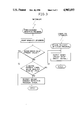
- FIG. 3 is a flowchart for indicating the runaway detecting process.
- FIG. 1 is a block diagram of the hardware for executing the runaway detecting system for the CPU according to the invention.
- reference numeral 1 designates a CPU.
- Reference numeral 2 denotes a resetter circuit.
- the resetter 2 is connected to a power switch 3 and the CPU 1, and is started by the ON of the power switch 3 or the output of the CPU 1 to output a reset signal to the CPU 1 and other system units.
- FIG. 2 is a flowchart for indicating the main process of the runaway detecting system for the CPU according to the invention.
- the runaway detecting system starts the first runaway detecting program after turning OFF the runaway detection output from the initialized state of the CPU 1.
- the first runaway detecting program flows a loop while receiving a periodic interrupt signal of a timer during resetting of the error counting.
- FIG. 3 shows a flowchart for indicating the process for detecting the runaway of the CPU.
- the first runaway detecting program which receives the periodic interrupt by the timer incrementally or decrementally counts the error by the interrupt. Then, decision whether the error count coincides with the preset predetermined value or not is made. If not coincident, the timer of the second runaway detecting program is restarted (reset) so that the second runaway detecting program is not processed by the overflowing interrupt of the timer, and is returned to a main loop.
- decision for comparing the value of the timer of the second runaway detecting program with a predetermined value is made, and the process is returned only when the value of the timer is smaller than the predetermined value.
- the decision for comparing the value of the second timer with the predetermined value concretely checks whether the timer of the second runaway detecting program is restarted or not in a short period (predetermined time). When arriving at the predetermined value, a malfunction occurs in the program so that a reason, such as no passage of a normal loop, exists. Accordingly, the second runaway detecting program is processed irrespective of the error count by the first runaway detecting program, i.e., the resetter 2 is driven to output a reset signal and to initialize the CPU 1.
- the timer of the second runaway detecting program is not started (reset), but the overflow of the timer occurs to drive the resetter 2.
- the flowing lines (1) or (2) is conducted only when the CPU 1 is regarded as being run away.
- the runaway detecting system for the CPU automatically processes (carries out) the second runaway detecting program by the overflow of the timer when the first runaway detecting program is stopped by the runaway, and when the second runaway detecting program is stopped by the runaway, it is automatically restarted by the first runaway detecting program. Even when the second runaway detecting program does not pass the normal loop or the interrupt of the timer is executed within a predetermined time due to a cause, such as a malfunction in addressing, the resetter 2 is driven to process the resetting.
- the process such as an initialization is immediately executed when the CPU is regarded as being run away to prevent in advance the motor or the circuit from being damaging due to the runaway of the CPU in a software.
Abstract
Description
Claims (8)
Applications Claiming Priority (2)
| Application Number | Priority Date | Filing Date | Title |
|---|---|---|---|
| JP62-56125 | 1987-03-11 | ||
| JP62056125A JPS63221437A (en) | 1987-03-11 | 1987-03-11 | Detecting system for cpu runaway |
Publications (1)
| Publication Number | Publication Date |
|---|---|
| US4903193A true US4903193A (en) | 1990-02-20 |
Family
ID=13018350
Family Applications (1)
| Application Number | Title | Priority Date | Filing Date |
|---|---|---|---|
| US07/123,187 Expired - Fee Related US4903193A (en) | 1987-03-11 | 1987-11-20 | Runaway detecting system for CPU |
Country Status (2)
| Country | Link |
|---|---|
| US (1) | US4903193A (en) |
| JP (1) | JPS63221437A (en) |
Cited By (12)
| Publication number | Priority date | Publication date | Assignee | Title |
|---|---|---|---|---|
| US5109506A (en) * | 1989-06-19 | 1992-04-28 | International Business Machines Corp. | Microcomputer system including a microprocessor reset circuit |
| US5327362A (en) * | 1991-01-16 | 1994-07-05 | Nec Corporation | System for detecting a runaway of a microcomputer |
| US5388254A (en) * | 1992-03-27 | 1995-02-07 | International Business Machines Corporation | Method and means for limiting duration of input/output (I/O) requests |
| US5408648A (en) * | 1989-07-25 | 1995-04-18 | Japan Electronic Control Systems Co., Ltd. | Method and apparatus for diagnosing CPU for CPU-runaway-preventing circuit |
| US5500809A (en) * | 1992-08-31 | 1996-03-19 | Sharp Kabushiki Kaisha | Microcomputer system provided with mechanism for controlling operation of program |
| US5594865A (en) * | 1991-12-11 | 1997-01-14 | Fujitsu Limited | Watchdog timer that can detect processor runaway while processor is accessing storage unit using data comparing unit to reset timer |
| US5652836A (en) * | 1995-05-31 | 1997-07-29 | Samsung Electronics Co., Ltd. | CPU reset circuit |
| US5774649A (en) * | 1995-04-07 | 1998-06-30 | Samsung Electronics Co., Ltd. | Microprocessor malfunction prevention circuit |
| US5873027A (en) * | 1993-07-16 | 1999-02-16 | Matsushita Electric Industrial Co., Ltd. | Mobile radio system with control over radio wave output if a malfunction is detected |
| US20110298515A1 (en) * | 2010-06-04 | 2011-12-08 | Samsung Electronics Co. Ltd. | System reset circuit and method |
| US20120254658A1 (en) * | 2009-10-15 | 2012-10-04 | L E Tech Co., Ltd. | Microcomputer and method of operation thereof |
| US20130111276A1 (en) * | 2011-10-28 | 2013-05-02 | Kabushiki Kaisha Toshiba | Periodic error detection method and periodic error detection circuit |
Families Citing this family (1)
| Publication number | Priority date | Publication date | Assignee | Title |
|---|---|---|---|---|
| JPH08115235A (en) * | 1994-10-14 | 1996-05-07 | Honda Motor Co Ltd | Abnormality detector for controller and method therefor |
Citations (3)
| Publication number | Priority date | Publication date | Assignee | Title |
|---|---|---|---|---|
| US4752930A (en) * | 1985-06-24 | 1988-06-21 | Mitsubishi Denki Kabushiki Kaisha | Watch dog timer |
| US4796211A (en) * | 1986-01-13 | 1989-01-03 | Oki Electric Industry Co., Ltd. | Watchdog timer having a reset detection circuit |
| US4803682A (en) * | 1985-03-04 | 1989-02-07 | Sanyo Electric Co., Ltd. | Resetting system |
Family Cites Families (2)
| Publication number | Priority date | Publication date | Assignee | Title |
|---|---|---|---|---|
| JPS58140853A (en) * | 1982-02-15 | 1983-08-20 | Kawai Musical Instr Mfg Co Ltd | Malfunction detecting and releasing system of processor |
| JPS59223860A (en) * | 1983-06-02 | 1984-12-15 | Mitsubishi Electric Corp | Fault diagnosis method of data processor |
-
1987
- 1987-03-11 JP JP62056125A patent/JPS63221437A/en active Pending
- 1987-11-20 US US07/123,187 patent/US4903193A/en not_active Expired - Fee Related
Patent Citations (3)
| Publication number | Priority date | Publication date | Assignee | Title |
|---|---|---|---|---|
| US4803682A (en) * | 1985-03-04 | 1989-02-07 | Sanyo Electric Co., Ltd. | Resetting system |
| US4752930A (en) * | 1985-06-24 | 1988-06-21 | Mitsubishi Denki Kabushiki Kaisha | Watch dog timer |
| US4796211A (en) * | 1986-01-13 | 1989-01-03 | Oki Electric Industry Co., Ltd. | Watchdog timer having a reset detection circuit |
Cited By (18)
| Publication number | Priority date | Publication date | Assignee | Title |
|---|---|---|---|---|
| US5109506A (en) * | 1989-06-19 | 1992-04-28 | International Business Machines Corp. | Microcomputer system including a microprocessor reset circuit |
| US5408648A (en) * | 1989-07-25 | 1995-04-18 | Japan Electronic Control Systems Co., Ltd. | Method and apparatus for diagnosing CPU for CPU-runaway-preventing circuit |
| US5327362A (en) * | 1991-01-16 | 1994-07-05 | Nec Corporation | System for detecting a runaway of a microcomputer |
| US5594865A (en) * | 1991-12-11 | 1997-01-14 | Fujitsu Limited | Watchdog timer that can detect processor runaway while processor is accessing storage unit using data comparing unit to reset timer |
| US5388254A (en) * | 1992-03-27 | 1995-02-07 | International Business Machines Corporation | Method and means for limiting duration of input/output (I/O) requests |
| US5500809A (en) * | 1992-08-31 | 1996-03-19 | Sharp Kabushiki Kaisha | Microcomputer system provided with mechanism for controlling operation of program |
| US5873027A (en) * | 1993-07-16 | 1999-02-16 | Matsushita Electric Industrial Co., Ltd. | Mobile radio system with control over radio wave output if a malfunction is detected |
| US6336040B1 (en) | 1993-07-16 | 2002-01-01 | Matsushita Electric Industrial Co., Ltd. | Mobile radio system with control over radio wave output if a malfunction is detected |
| US5774649A (en) * | 1995-04-07 | 1998-06-30 | Samsung Electronics Co., Ltd. | Microprocessor malfunction prevention circuit |
| US5652836A (en) * | 1995-05-31 | 1997-07-29 | Samsung Electronics Co., Ltd. | CPU reset circuit |
| US20120254658A1 (en) * | 2009-10-15 | 2012-10-04 | L E Tech Co., Ltd. | Microcomputer and method of operation thereof |
| US8954801B2 (en) * | 2009-10-15 | 2015-02-10 | L E Tech Co., Ltd. | Microcomputer and method of operation thereof |
| US20110298515A1 (en) * | 2010-06-04 | 2011-12-08 | Samsung Electronics Co. Ltd. | System reset circuit and method |
| US8624648B2 (en) * | 2010-06-04 | 2014-01-07 | Samsung Electronics Co., Ltd. | System reset circuit and method |
| US20130111276A1 (en) * | 2011-10-28 | 2013-05-02 | Kabushiki Kaisha Toshiba | Periodic error detection method and periodic error detection circuit |
| CN103092734A (en) * | 2011-10-28 | 2013-05-08 | 株式会社东芝 | Periodic error detection method and periodic error detection circuit |
| US8887004B2 (en) * | 2011-10-28 | 2014-11-11 | Kabushiki Kaisha Toshiba | Periodic error detection method and periodic error detection circuit |
| CN103092734B (en) * | 2011-10-28 | 2015-07-29 | 株式会社东芝 | Cycle error-detecting method and cycle error detect circuit |
Also Published As
| Publication number | Publication date |
|---|---|
| JPS63221437A (en) | 1988-09-14 |
Similar Documents
| Publication | Publication Date | Title |
|---|---|---|
| US4903193A (en) | Runaway detecting system for CPU | |
| US4405982A (en) | Arrangement for monitoring the function of a programmable electronic switching circuit | |
| US4566111A (en) | Watchdog timer | |
| JPH0528063A (en) | Microcomputer | |
| KR980004041A (en) | System Recovery Device | |
| US6269443B1 (en) | Method and apparatus for automatically selecting CPU clock frequency multiplier | |
| KR100294523B1 (en) | Microcomputer | |
| JPS5878239A (en) | Operation controlling circuit | |
| JP2659067B2 (en) | Microcomputer reset circuit | |
| JP2516711B2 (en) | Watchdog timer device | |
| JPH0444132A (en) | Circuit and system for detection of runaway | |
| JPS63271545A (en) | Watch dog timer | |
| JPS6389941A (en) | Monitor and control equipment for microprocessor applied equipment | |
| JPH01154258A (en) | Malfunction detecting device using watchdog timer | |
| JPS59162336A (en) | Violent running preventive device of engine idle | |
| KR100329017B1 (en) | Watchdog Timer Device | |
| JPS63316146A (en) | Microcomputer | |
| JPS63280345A (en) | Detection of program abnormality | |
| JPH04182745A (en) | Cpu run away detection circuit | |
| JPH02294220A (en) | Cpu automatic reset circuit in microcomputer control | |
| JPS56148184A (en) | Controlling device of stopping dc motor | |
| JPH04225411A (en) | Reset circuit | |
| JPH09237205A (en) | Program runaway detection device | |
| JPH0588943A (en) | Watchdog timer | |
| JPH09179748A (en) | Data processor |
Legal Events
| Date | Code | Title | Description |
|---|---|---|---|
| AS | Assignment |
Owner name: ALPS ELECTRIC CO., LTD., 1-7 YUKIGAYA OTSUKA-CHO, Free format text: ASSIGNMENT OF ASSIGNORS INTEREST.;ASSIGNOR:NAKAMURA, ISAO;REEL/FRAME:004814/0231 Effective date: 19871106 |
|
| FEPP | Fee payment procedure |
Free format text: PAYOR NUMBER ASSIGNED (ORIGINAL EVENT CODE: ASPN); ENTITY STATUS OF PATENT OWNER: LARGE ENTITY |
|
| CC | Certificate of correction | ||
| FEPP | Fee payment procedure |
Free format text: PAYOR NUMBER ASSIGNED (ORIGINAL EVENT CODE: ASPN); ENTITY STATUS OF PATENT OWNER: LARGE ENTITY Free format text: PAYER NUMBER DE-ASSIGNED (ORIGINAL EVENT CODE: RMPN); ENTITY STATUS OF PATENT OWNER: LARGE ENTITY |
|
| FPAY | Fee payment |
Year of fee payment: 4 |
|
| FPAY | Fee payment |
Year of fee payment: 8 |
|
| REMI | Maintenance fee reminder mailed | ||
| LAPS | Lapse for failure to pay maintenance fees | ||
| STCH | Information on status: patent discontinuation |
Free format text: PATENT EXPIRED DUE TO NONPAYMENT OF MAINTENANCE FEES UNDER 37 CFR 1.362 |
|
| FP | Lapsed due to failure to pay maintenance fee |
Effective date: 20020220 |