US4901809A - Device for positioning and attaching an auxiliary snow-chain device for motor vehicles - Google Patents
Device for positioning and attaching an auxiliary snow-chain device for motor vehicles Download PDFInfo
- Publication number
- US4901809A US4901809A US07/325,265 US32526589A US4901809A US 4901809 A US4901809 A US 4901809A US 32526589 A US32526589 A US 32526589A US 4901809 A US4901809 A US 4901809A
- Authority
- US
- United States
- Prior art keywords
- cage
- lug
- chain
- vehicle
- longitudinal axis
- Prior art date
- Legal status (The legal status is an assumption and is not a legal conclusion. Google has not performed a legal analysis and makes no representation as to the accuracy of the status listed.)
- Expired - Fee Related
Links
Images
Classifications
-
- B—PERFORMING OPERATIONS; TRANSPORTING
- B60—VEHICLES IN GENERAL
- B60B—VEHICLE WHEELS; CASTORS; AXLES FOR WHEELS OR CASTORS; INCREASING WHEEL ADHESION
- B60B39/00—Increasing wheel adhesion
- B60B39/003—Vehicle mounted non-skid chains actuated by centrifugal force
Definitions
- This invention relates to a device for positioning and attaching an auxiliary snow-chain device intended to be arranged under a motor vehicle, of the type including a cage accommodating means for driving a swivel arm, one of the ends of which is integral with the driving means and the other end provided with a small wheel comprising lengths of chain, this arm being able to occupy a free position and an engaged position during which the small wheel, resting against the inner sidewall of the wheel of the vehicle, must be situated in a specifically defined plane relative to said vehicle wheel.
- the positioning and attachment of chain devices raise several interrelated problems.
- First is that of the choice of means utilized for ensuring a really reliable attachment considering the significant stresses to which these means are subjected when the chain device is in use. Then, it is desirable for the means to facilitate mounting of the device.
- Third, directly associated with these first problems is that of the positioning of the snow-chain device and, correlatively, that of the adjustment of the small wheel, the position of the latter relative to the inner sidewall of the wheel against which it is to rest having to satisfy certain conditions.
- the successive approach toward the ideal position of the small wheel is, in fact, carried out especially by acting upon the means for positioning and attaching the snow-chain device.
- the final adjustment of the small wheel relative to the vehicle wheel is made by acting upon specific means, such as ball-and-socket joints, arranged in the zone of connection between the swivel arm and the small wheel.
- the cage comprises least two suspension locations, each having a specific conformation, which conformations each co-operate with one or more locking and attachment components and, at the same time, allow not only direct or indirect securing of the snow-chain device under the vehicle and its positioning, but also the adjustment of the small wheel in the specific plane.
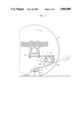
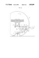
- FIG. 1 is an overall diagram of a first embodiment of the invention
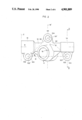
- FIG. 2 is a top view of the cage of this embodiment
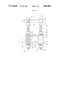
- FIG. 3 is a partial section taken on the line III--III of FIG. 2, with the attaching means,
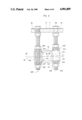
- FIG. 4 is a partial section analogous to that of FIG. 3,
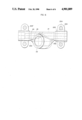
- FIG. 5 is an overall diagram of a second embodiment of the invention.
- FIG. 6 is a top view of the cage of this embodiment.
- FIG. 1 shows very schematically an example of the mounting of the snow-chain device in the overall arrangement.
- the cage 1 accommodates the driving components of the arm 3 fixed, at one of its ends, to an arbor emerging from the portion 11 of the cage 1 and provided, at the other end, with a small wheel 4 capable of resting against the inner sidewall of the wheel 6 of the vehicle and provided with lengths of chain 5.
- the cage comprises three attachment locations 101, 102, and 103 co-operating with attachment components, so that the cage is integral with elements of the vehicle under which the snow-chain device is arranged, such as a frustoconical portion of an axle or, as in the embodiment illustrated, a suspension-spring bracket 8, via an auxiliary element, here a rigid plate 7.
- an intermediate element 7, not necessarily a plate, will have to be provided for, even though the cage 1 as designed does not exclude the possibility of direct attachment.
- FIG. 2 is a top view of a first modification of the cage 1 accommodating the means for driving the small-wheel arm, or swivel arm, 3.
- the design of the snow-chain device used will preferably be that disclosed in the aforementioned co-pending application.
- the cage 1 has a component 10 of a generally elongated shape with a longitudinal axis 9; the middle zone of the component 10 comprises a body 11, disposed obliquely, the axis of the latter, not shown, forming an angle ⁇ , or 180°- ⁇ , with the longitudinal axis 9.
- the cage 1 is preferably a casting.
- a rack may move in the component 10, under the influence of actuating means--made up, for example, of a single- or double-action hydraulic piston--accommodated by a cage 2 situated adjacent to the component 10.
- the rack meshes with a pinion accommodated in the body 11, from which an arbor emerges to which the smallwheel or swivel arm 3 is fixed. None of these means are shown in the drawing. They are mentioned by way of indication as the attaching device can be adopted for any other auxiliary snow-chain devices.
- the cage 1 At three locations--viz., at the two ends 13 and 14 of the component 10, on the one hand, and in the middle zone 12 of that body, i.e., in the zone of the center plane indicated by line 15', which line is perpendicular to the longitudinal axis 9, and opposite to the body 11, on the other hand--the cage 1 comprises suspension locations 101, 102, 103 for attaching the cage 1 under the vehicle.
- these locations disposed alternately on both sides of the longitudinal axis 9 constitute a triangular suspension.
- FIGS. 3 and 4 are partial sections taken on the line III--III of FIG. 2, showing the cage 1 in two different positions.
- the body 11 of the cage 1 is not shown in FIGS. 3 and 4, however.
- the lugs 101, 102, 103 are connected to the component 10 by ribs (not shown); the assembly 10, 11, 101, 102, 103, 102, 103 may be machine welded, but as already mentioned, a cast part is preferred.
- Each of the lugs 101, 102, 103 is made up of a truncated cylinder having a respective axis 103', 102', 103' and includes a central bore 104. These axes are all at right angles to the longitudinal axis 9 and are preferably parallel to one another; by the same token, in this embodiment, each lug has a general shape identical to that of the other two. A basic particularity resides in the rounded conformation of the lower and upper faces 105, 105' (lug 101), 106, 106' (lug 102), and 107, 107' (lug 103), the utility of which will readily be understood below.
- the faces are domed, i.e., convex; the radius of curvature is situated on the inside of the lug and chosen at the point of intersection between the center plane 15 (FIG. 3) and the respective axis 101', 102', 103' of the lug.
- Concave faces might equally well be used, f course, or even alternately concave/convex. In any case, however, the same radius of curvature will be chosen.
- the mode of attachment of the cage 1 will now be explained with reference solely to the lug 101 for the sake of simplicity.
- the end of a threaded rod or screw 108 passes all the way through the bore 104 of the lug 101.
- the diameter of the bore 104 is appreciably greater than the diameter of the screw 108.
- a nut 109, a spring washer 111, and an interposed element 110 permit locking of the lug, and hence of the cage 1, by tightening the nuts 109 on the respective two faces of the lug.
- the surface 112 of the interposed element 110 directly adjacent to the faces 105 and 105', respectively, must match that face; in other words, the curvature will be identical.
- the screw 108 passes through a bore 16 in the auxiliary element, in the present case the plate 7.
- the screw 108 is made integral with the plate 7 by the action of the screw head 113 pressing against the top face 17 of the plate 7 and of the check nut 109'.
- a spring washer 111' placed between the bottom face 18 of the plate 7 and the nut 109', will ensure better locking.
- Other analogous attachment means may be utilized.
- the plate 7 is integral with one or more components of the vehicle, as has already been stated above.
- the cage 1 thus designed will ideally permit the snowchain device to be positioned prior to its final locking (FIG. 4): in a first phase, the device is put in place approximately, i.e., it will be ensured that the small wheel 4, in operating position, hence placed against the inner sidewall of the wheel 6 of the vehicle, is situated in a plane approaching the predetermined ideal plane.
- the fine positioning will be undertaken, and thus the final adjustment of the small wheel in the aforementioned plane.
- the adjusting nuts 109 of the lugs will be acted upon so as to modify the orientation of the center plane relative to a horizontal plane (e.g., the horizontal plane 15") and, correlatively, that of the plane of the small wheel 4.
- a horizontal plane e.g., the horizontal plane 15
- the cage 1 will be locked by tightening each of the nuts 109 on the respective top and bottom faces of the lugs.
- This triangle is situated in the center plane 15; its vertices are constituted by the intersections of this plane with the axes 101', 102', and 103'.
- the "tilting" of the cage 1, i.e., the positioning thereof, may be achieved in several ways. For example, let it be assumed that only lug 101 is to be acted upon, causing it to be raised or lowered, as need be, with the aid of the screw-and-nut assembly 108, 109, and that it is not desired to vary the positions of the lugs 102 and 103.
- the cage 1, hence the center plane 15 determined by the triangle 31, 32, 33 will rotate about the axis 31, with the lugs 102, 103 acting as ball-and-socket joints.
- the plane 15 may tilt about the axes 32 or 33.
- the center plane 15, i.e., the triangle 31, 32, 33 will be able to pivot in all directions about the horizontal. All these planes, whatever their orientation, will pass through a point 19 which is the center of gravity of the triangle 31, 32, 33 (FIG. 2).
- this point may itself move vertically, parallel to the axes 101', 102', 103'.
- this point 19 may be on the longitudinal axis 9, as shown in FIG. 4.
- the angle ⁇ may vary within a range of about 0° to 5°.
- the auxiliary snow-chain device provided with a positioning and attachment device such as described may be mounted on all types of vehicles. A shorter swivel arm will naturally be utilized for light vehicles than for heavy vehicles.
- the diameter of the attachment screws, as well as of the matching washers i.e., parts analogous to those designated above as 108, 109, 110, 111) will be adapted accordingly. Screws of 12 mm diameter may be used, for instance.
- the present invention optimally meets all the requirements set forth at the beginning. It combines precision of positioning of the snow-chain device and hence of the adjustment of the small wheel in the ideal plane, reliability of the attachment, ease of mounting, and efficiency of design.
- FIGS. 5 and 6 A second embodiment is illustrated in FIGS. 5 and 6.
- the cost price of this embodiment is slightly less than that of the first embodiment described.
- the possibilities of orientation, represented by the angle ⁇ , are reduced, however.
- FIG. 5 shows diagrammatically the overall arrangement of the snow-chain device.
- the latter differs from the first embodiment in that the driving cage 20, which accommodates the means for driving the smallwheel or swivel arm 3 (analogous to the means mentioned earlier), has only two suspension locations instead of three.
- the cage 20 is made up of a component 21 of generally elongated shape with a longitudinal axis 23, and of a body 22 disposed obliquely relative to the component 21, the respective axes of these two parts forming an angle slightly other than 90°.
- the cage 20 is preferably a cast part.
- the cross-section of the component 21 is preferably cylindrical.
- the attachment locations 201, 202 at the site of which the diameter is slightly reinforced, are disposed at each of the ends of the component 21.
- Mounted at each location 201, 202 are regulating and attachment means, e.g., brackets shown schematically as 203. These brackets are squeezed at the locations 201 and 202, respectively, in a manner known per se, by means of screws 204 and nuts (the latter not being shown).
- the cage 20 will in most cases be integral with an auxiliary element, e.g., with an intermediate plate 7, by means of the same screws 204, the plate 7 again being fixed in turn to elements 8 of the vehicle.
- any other known locking means might be used in lieu of the brackets 203, 203' and screws/nuts 204.
- Positioning of the device is achieved, before tightening, by displacement of the cage 20 along the longitudinal axis in one direction or the other, on the one hand, and on the other hand by a slight inclination ⁇ of the axis 23 about the horizontal (FIG. 5), but only in the direction of the length of the cage 20.
- This possibility of inclination may be improved by providing, at the attachment locations, a rounded shape 205, shown in dot-dash lines at the location 201 in FIG. 6.
- the cage 20 may equally well be rotated about its axis 23.
- this second embodiment offers less extensive possibilities of orientation of the driving cage than those of the first embodiment.
- the size of the cage is slightly reduced, as well as the cost. The preference may be given to one or the other of the embodiments described, as the case may be.
Landscapes
- Engineering & Computer Science (AREA)
- Mechanical Engineering (AREA)
- Vehicle Body Suspensions (AREA)
- Axle Suspensions And Sidecars For Cycles (AREA)
- Steering-Linkage Mechanisms And Four-Wheel Steering (AREA)
- Automatic Cycles, And Cycles In General (AREA)
Applications Claiming Priority (2)
| Application Number | Priority Date | Filing Date | Title |
|---|---|---|---|
| CH1136/88 | 1988-03-25 | ||
| CH113688 | 1988-03-25 |
Publications (1)
| Publication Number | Publication Date |
|---|---|
| US4901809A true US4901809A (en) | 1990-02-20 |
Family
ID=4203330
Family Applications (1)
| Application Number | Title | Priority Date | Filing Date |
|---|---|---|---|
| US07/325,265 Expired - Fee Related US4901809A (en) | 1988-03-25 | 1989-03-17 | Device for positioning and attaching an auxiliary snow-chain device for motor vehicles |
Country Status (7)
| Country | Link |
|---|---|
| US (1) | US4901809A (fr) |
| EP (1) | EP0334810B1 (fr) |
| JP (1) | JPH0228008A (fr) |
| CN (1) | CN1037109A (fr) |
| AT (1) | ATE88418T1 (fr) |
| CA (1) | CA1322150C (fr) |
| DE (1) | DE68906065D1 (fr) |
Cited By (10)
| Publication number | Priority date | Publication date | Assignee | Title |
|---|---|---|---|---|
| US5076379A (en) * | 1990-11-19 | 1991-12-31 | Bahr William T | Mechanism for translation of linear motion to rotary motion |
| WO1999038714A1 (fr) * | 1998-01-29 | 1999-08-05 | Vbg Produkter Ab | Dispositif d'actionnement |
| US6651783B1 (en) | 2000-08-28 | 2003-11-25 | John H. Atkinson, Jr. | Adjustable mounting assembly for a rapidly-deployable ice chain system for wheeled vehicles |
| US20050161929A1 (en) * | 2004-01-23 | 2005-07-28 | Rosenbalm Ronald D. | Anti-skid tire chain device |
| WO2005070737A1 (fr) * | 2004-01-13 | 2005-08-04 | Smith Fred P | Systeme d'asservissement electrique a couple limite permettant de deployer pour un vehicule un systeme de traction par chenille sur la neige |
| KR100507138B1 (ko) * | 2001-12-26 | 2005-08-09 | 현대자동차주식회사 | 차량의 스노우체인 구동제어 장치 |
| US20050262974A1 (en) * | 2003-04-02 | 2005-12-01 | Engvall David P | Quick adjusting pliers |
| US20110146866A1 (en) * | 2009-12-19 | 2011-06-23 | Samad Jafari Valilou | Automatic tire chain system |
| US20190184743A1 (en) * | 2017-12-20 | 2019-06-20 | Dusawn Holdings LLC | Tire Chains Apparatus |
| CN115157928A (zh) * | 2022-09-07 | 2022-10-11 | 之江实验室 | 一种全自动车载防滑装置 |
Families Citing this family (1)
| Publication number | Priority date | Publication date | Assignee | Title |
|---|---|---|---|---|
| SE467456B (sv) * | 1988-10-20 | 1992-07-20 | Onspot Ab | Armlagring vid slirskydd |
Citations (6)
| Publication number | Priority date | Publication date | Assignee | Title |
|---|---|---|---|---|
| US2283948A (en) * | 1941-04-09 | 1942-05-26 | Herbert N Ridgway | Automobile traction device |
| US2790514A (en) * | 1956-03-12 | 1957-04-30 | Robinson Luther | Anti-skid apparatus for vehicles |
| US3658158A (en) * | 1970-02-17 | 1972-04-25 | Chauncey P Saupp | Anti-skid device for motor vehicles |
| EP0195973A1 (fr) * | 1985-03-14 | 1986-10-01 | Gerd Schulz Fahrzeug- und Container-Technik | Dispositif à chaînes centrifugées pour véhicules automobiles |
| US4751975A (en) * | 1985-07-19 | 1988-06-21 | Rud-Kettenfabrik Rieger & Dietz Gmbh U. Co. | Anti-skid device for motor vehicles |
| US4800939A (en) * | 1986-07-03 | 1989-01-31 | On Spot Ab | Anti-skid device |
Family Cites Families (1)
| Publication number | Priority date | Publication date | Assignee | Title |
|---|---|---|---|---|
| SE447811B (sv) * | 1985-03-01 | 1986-12-15 | Onspot Ab | Slirskydd |
-
1989
- 1989-03-15 EP EP89810205A patent/EP0334810B1/fr not_active Expired - Lifetime
- 1989-03-15 AT AT89810205T patent/ATE88418T1/de not_active IP Right Cessation
- 1989-03-15 DE DE8989810205T patent/DE68906065D1/de not_active Expired - Lifetime
- 1989-03-17 US US07/325,265 patent/US4901809A/en not_active Expired - Fee Related
- 1989-03-23 CN CN89101762A patent/CN1037109A/zh active Pending
- 1989-03-23 CA CA000594573A patent/CA1322150C/fr not_active Expired - Fee Related
- 1989-03-27 JP JP1076374A patent/JPH0228008A/ja active Pending
Patent Citations (6)
| Publication number | Priority date | Publication date | Assignee | Title |
|---|---|---|---|---|
| US2283948A (en) * | 1941-04-09 | 1942-05-26 | Herbert N Ridgway | Automobile traction device |
| US2790514A (en) * | 1956-03-12 | 1957-04-30 | Robinson Luther | Anti-skid apparatus for vehicles |
| US3658158A (en) * | 1970-02-17 | 1972-04-25 | Chauncey P Saupp | Anti-skid device for motor vehicles |
| EP0195973A1 (fr) * | 1985-03-14 | 1986-10-01 | Gerd Schulz Fahrzeug- und Container-Technik | Dispositif à chaînes centrifugées pour véhicules automobiles |
| US4751975A (en) * | 1985-07-19 | 1988-06-21 | Rud-Kettenfabrik Rieger & Dietz Gmbh U. Co. | Anti-skid device for motor vehicles |
| US4800939A (en) * | 1986-07-03 | 1989-01-31 | On Spot Ab | Anti-skid device |
Cited By (14)
| Publication number | Priority date | Publication date | Assignee | Title |
|---|---|---|---|---|
| US5076379A (en) * | 1990-11-19 | 1991-12-31 | Bahr William T | Mechanism for translation of linear motion to rotary motion |
| WO1999038714A1 (fr) * | 1998-01-29 | 1999-08-05 | Vbg Produkter Ab | Dispositif d'actionnement |
| US6409215B1 (en) | 1998-01-29 | 2002-06-25 | Vbg Produkter Ab | Operating device for anti-skid devices for vehicles |
| US6651783B1 (en) | 2000-08-28 | 2003-11-25 | John H. Atkinson, Jr. | Adjustable mounting assembly for a rapidly-deployable ice chain system for wheeled vehicles |
| KR100507138B1 (ko) * | 2001-12-26 | 2005-08-09 | 현대자동차주식회사 | 차량의 스노우체인 구동제어 장치 |
| US20050262974A1 (en) * | 2003-04-02 | 2005-12-01 | Engvall David P | Quick adjusting pliers |
| WO2005070737A1 (fr) * | 2004-01-13 | 2005-08-04 | Smith Fred P | Systeme d'asservissement electrique a couple limite permettant de deployer pour un vehicule un systeme de traction par chenille sur la neige |
| US20050161929A1 (en) * | 2004-01-23 | 2005-07-28 | Rosenbalm Ronald D. | Anti-skid tire chain device |
| US7118130B2 (en) | 2004-01-23 | 2006-10-10 | Onspot Of North America, Inc. | Anti-skid tire chain device |
| US20110146866A1 (en) * | 2009-12-19 | 2011-06-23 | Samad Jafari Valilou | Automatic tire chain system |
| US20190184743A1 (en) * | 2017-12-20 | 2019-06-20 | Dusawn Holdings LLC | Tire Chains Apparatus |
| US10675914B2 (en) * | 2017-12-20 | 2020-06-09 | Dusawn Holdings LLC | Tire chains apparatus |
| CN115157928A (zh) * | 2022-09-07 | 2022-10-11 | 之江实验室 | 一种全自动车载防滑装置 |
| CN115157928B (zh) * | 2022-09-07 | 2023-03-21 | 之江实验室 | 一种全自动车载防滑装置 |
Also Published As
| Publication number | Publication date |
|---|---|
| DE68906065D1 (de) | 1993-05-27 |
| CN1037109A (zh) | 1989-11-15 |
| CA1322150C (fr) | 1993-09-14 |
| EP0334810A1 (fr) | 1989-09-27 |
| JPH0228008A (ja) | 1990-01-30 |
| EP0334810B1 (fr) | 1993-04-21 |
| ATE88418T1 (de) | 1993-05-15 |
Similar Documents
| Publication | Publication Date | Title |
|---|---|---|
| US4901809A (en) | Device for positioning and attaching an auxiliary snow-chain device for motor vehicles | |
| US7845658B2 (en) | Steerable and liftable independent suspension system | |
| US5511808A (en) | Flexible fender mount | |
| KR100347071B1 (ko) | 킹핀조절장치 | |
| AU668826B2 (en) | Parallelogram lift axle suspension system with a control for axle caster adjustment | |
| US4908925A (en) | Heavy duty automotive wheel hub puller | |
| US4418938A (en) | Vehicle strut suspension with camber adjustment | |
| US5275378A (en) | Automotive jack | |
| US4618162A (en) | Device and method for adjusting camber in a strut-type vehicle suspension | |
| US4462241A (en) | Wheel alignment device | |
| US20080231010A1 (en) | Motor Vehicle Chassis | |
| US2684253A (en) | Vehicle wheel mounting with camber adjustment | |
| US4511048A (en) | Jib crane system having a rotatable mast | |
| CN1599677A (zh) | 用于悬架调节装置的刚性垫片止动系统 | |
| EP0890501B1 (fr) | Système à ressort pneumatique avec barres précontraintes | |
| EP0663307A1 (fr) | Ensemble de ressort hélicoidal réglable | |
| US12337637B2 (en) | Clamp group and round axle with alignment features | |
| CN212269384U (zh) | 一种臂架总成及拱架安装台车 | |
| US5540417A (en) | Adjustable coil spring assembly | |
| US4848130A (en) | Apparatus for use with vehicle frame straightener | |
| US20090016809A1 (en) | Joint arrangement | |
| CN222742489U (zh) | 一种具有增强结构的汽车控制臂 | |
| SU1125148A1 (ru) | Устройство дл регулировани развала колес транспортного средства | |
| US3218032A (en) | Tool for adjusting vehicle steering knuckle | |
| IE903219A1 (en) | A bracket for a mudgard support |
Legal Events
| Date | Code | Title | Description |
|---|---|---|---|
| AS | Assignment |
Owner name: BEKA ST-AUBIN SA, SWITZERLAND Free format text: ASSIGNMENT OF ASSIGNORS INTEREST.;ASSIGNOR:TSCHANNEN, HANS;REEL/FRAME:005032/0966 Effective date: 19890308 |
|
| FEPP | Fee payment procedure |
Free format text: PAYOR NUMBER ASSIGNED (ORIGINAL EVENT CODE: ASPN); ENTITY STATUS OF PATENT OWNER: SMALL ENTITY |
|
| FPAY | Fee payment |
Year of fee payment: 4 |
|
| REMI | Maintenance fee reminder mailed | ||
| LAPS | Lapse for failure to pay maintenance fees | ||
| FP | Lapsed due to failure to pay maintenance fee |
Effective date: 19980225 |
|
| STCH | Information on status: patent discontinuation |
Free format text: PATENT EXPIRED DUE TO NONPAYMENT OF MAINTENANCE FEES UNDER 37 CFR 1.362 |