US4901548A - Key head and key fitted with such a head - Google Patents
Key head and key fitted with such a head Download PDFInfo
- Publication number
- US4901548A US4901548A US07/174,403 US17440388A US4901548A US 4901548 A US4901548 A US 4901548A US 17440388 A US17440388 A US 17440388A US 4901548 A US4901548 A US 4901548A
- Authority
- US
- United States
- Prior art keywords
- key
- case
- cut section
- aforesaid
- locking means
- Prior art date
- Legal status (The legal status is an assumption and is not a legal conclusion. Google has not performed a legal analysis and makes no representation as to the accuracy of the status listed.)
- Expired - Fee Related
Links
Images
Classifications
-
- E—FIXED CONSTRUCTIONS
- E05—LOCKS; KEYS; WINDOW OR DOOR FITTINGS; SAFES
- E05B—LOCKS; ACCESSORIES THEREFOR; HANDCUFFS
- E05B19/00—Keys; Accessories therefor
- E05B19/04—Construction of the bow or head of the key; Attaching the bow to the shank
-
- Y—GENERAL TAGGING OF NEW TECHNOLOGICAL DEVELOPMENTS; GENERAL TAGGING OF CROSS-SECTIONAL TECHNOLOGIES SPANNING OVER SEVERAL SECTIONS OF THE IPC; TECHNICAL SUBJECTS COVERED BY FORMER USPC CROSS-REFERENCE ART COLLECTIONS [XRACs] AND DIGESTS
- Y10—TECHNICAL SUBJECTS COVERED BY FORMER USPC
- Y10T—TECHNICAL SUBJECTS COVERED BY FORMER US CLASSIFICATION
- Y10T70/00—Locks
- Y10T70/70—Operating mechanism
- Y10T70/7441—Key
- Y10T70/778—Operating elements
- Y10T70/7791—Keys
- Y10T70/7876—Bow or head
-
- Y—GENERAL TAGGING OF NEW TECHNOLOGICAL DEVELOPMENTS; GENERAL TAGGING OF CROSS-SECTIONAL TECHNOLOGIES SPANNING OVER SEVERAL SECTIONS OF THE IPC; TECHNICAL SUBJECTS COVERED BY FORMER USPC CROSS-REFERENCE ART COLLECTIONS [XRACs] AND DIGESTS
- Y10—TECHNICAL SUBJECTS COVERED BY FORMER USPC
- Y10T—TECHNICAL SUBJECTS COVERED BY FORMER US CLASSIFICATION
- Y10T70/00—Locks
- Y10T70/80—Parts, attachments, accessories and adjuncts
- Y10T70/8432—For key-operated mechanism
- Y10T70/8676—Key holders
Definitions
- This invention relates to a key head that forms by itself a jewel or similar element designed to receive, successively, keys of various shapes, comprising a rigid case featuring two opposite walls that form intake surface areas, one peripheral wall arranged between the two intake walls and one inner cavity into which a section cut from the head of any conventional key, including automobile keys, can be lodged in a removable manner, with the peripheral wall of the case displaying an opening for letting through the bit of the conventional key, as well as means for locking the cut section of the key head inside the cavity of the case in a position adjacent to the aforesaid passage opening, with these means preventing, in relation to the key head, any displacement of the cut section and of the bit in their plane, with the case formed, at least, by two parts for assembly that are held together in a detachable manner by means of assembly. It also concerns a key that displays such a head.
- a key head of this kind has already been described in the Belgian patent no. 904,684 granted to this applicant.
- This known key head is designed to serve as a jewel to be preserved and to which can be fitted various successive keys.
- This key head has the drawback that the intake walls alone are provided for locking the cut section of the key in the cavity of the case so as to prevent any rotary movement of the cut section in relation to the aforesaid case. Consequently, as soon as the key used displays a thickness that is very slightly less as compared to the peripheral wall of the case, there is the possibility of an undesired relative displacement between the bit and the case.
- the only means of assembly described for the key head according to this patent are means of glueing. These means have the drawback that changing the key can not be carried out by a private person since a jeweller or the vendor of the key head who is alone to know the appropriate solvent and its method of use will necessarily have to intervene.
- casings made of malleable plastic material into which the key heads can be fitted and by which they are partly covered.
- These envelopes serve only the purpose of differentiating one key from another and normally, a casing of this kind is not designed to be removed again from the key onto which it is fitted, although this is possible.
- a casing will be removed when it is worn or torn and if it is to be replaced by another casing that is new or of a different colour. If the casing removed is undamaged, then it can possibly serve again, provided the key to be encased displays the same head shape as the previous one.
- the object of this invention is to provide a key head designed to form a jewel or precious and ornamental item by itself, the fitting, locking and assembling means of which are not visible from outside or are visible only to a very limited extent.
- This key head must be able to serve for various keys of any nature, successively, according to the user's wish. It is the key head that is designed to be kept by the user and if he changes automobiles, for instance, it must be possible to use the key of his next automobile by means of the key head according to the invention in a manner that allows for perfect transmission of the tractive, pushing and twisting efforts applied to the key head according to the invention and from there to the key bit.
- the key head must not allow for any relative displacement between itself and the bit while the key is being maneuvered whichever the size of the key installed may be, in particular where thickness is concerned. Also, replacing one key by another in the key head according to the invention must be easily performed by the user himself. Only the cutting of the conventional key head will have to be performed by means of a special device that can be found at any keymaker's shop.
- the aforesaid locking means comprise stops provided on the inner side of the part of the case that displays the locking means, with these stops arranged in relation one to the other in such a manner as to rest against the peripheral outline of the section cut of the key, either against the entire outline or against part thereof.
- the height of some of the stops at least, will be maximum equal to the thickness of the thinnest conventional key heads in the event where these stops are arranged all around the section cut of the key.
- the aforesaid locking means consist of a recess provided on the inner face of the intake wall displayed by the aforesaid part of the case that features the locking means, with this recess displaying a previously determined shape, the peripheral outline of which will be smaller than any conventional key head, and the depth of which will be slightly less than or equal to the thickness of the thinnest conventional key heads.
- the aforesaid means of fixation are adjustable according to the thickness of the section cut of the conventional key head used.
- the aforesaid means of assembly of the parts of the case to be assembled are removable mechanical means of assembly, the part visible from the outside of which can be seen only on the peripheral wall of the case.
- these means of assembly are designed so as not to be visible from the outside subsequent to the assembly.
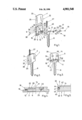
- FIG. 1 shows an exploded perspective view of a form of embodiment of a key fitted with a key head according to the invention.
- FIG. 2 shows a perspective view of the key according to FIG. 1 in the assembled state.
- FIG. 3 shows a front view of the inside of the part of the case to be assembled, displaying the means for locking and securing the section cut and the bit of the conventional key installed.
- FIG. 4 shows a sectional view according to line IV--IV of FIG. 2, to an enlarged scale.
- FIG. 5 shows a partial transverse sectional view of a variant of embodiment according to the invention.
- a key head designed to be fitted successively with keys of various shapes.
- This key head comprises a rigid case 1 that displays two opposite walls 2,3 that form intake surfaces on the outer side. These intake surfaces are designed not alone to take the tractive, pushing or twisting efforts applied by the fingers in view of transmitting them to the key, but also possibly as ornamental surface areas.
- the case 1 comprises, furthermore, a peripheral wall 4 arranged between the two intake walls 2 and 3. These latter walls and the peripheral wall 4 constitute the casing of an inner cavity 5 of the case 1. Into this cavity, a cut section 6 of any conventional key, including automobile keys, can be lodged in a removable manner, as shown by FIG. 1.
- the peripheral wall 4 of case 1 displays an opening 7 located close to the cavity 5 and this opening is designed to leave passage to the bit 8 of the conventional key used outside the case 1.
- the case 1 consists of two parts to be assembled.
- part 9 comprises the intake wall 3 and the parts 10,11 of the peripheral wall 4, located on both sides of the passage opening 7 for the bit 8.
- This part 9 to be assembled is fitted on the side directed toward the inside of the case with locking means for the cut section 6 of the conventional key head used.
- these locking means consist of a recess 12 on the inner face of the intake wall 3. This recess displays an approximately rectangular shape with slightly rounded corners.
- the recess 12 is limited by two ribs 15,16 that are projecting inwards in relation to the inner face of the intake wall 3.
- the recess 12 thus displays a previously determined shape, the peripheral outline of which will be smaller than any conventional key head. Consequently, the latter can always be cut according to the outline of the recess.
- the parts 10 and 11 of the peripheral wall 4, on one hand, and the thickening 14, on the other serve as stops that since they are resting against the peripheral outline of the cut section 6 of the key, prevent any displacement of the bit 8 and of the cut section 6 in relation to the part 9 of the case 1, in the longitudinal direction of the bit.
- the ribs 15,16 also serve as stops that since they are resting against the peripheral outline of the cut section 6 of the key, prevent any displacement of the bit 8 and of the cut section 6 of the key in relation to the part 9 of the case 1, laterally to the longitudinal direction of the bit. Consequently, once the cut section finds itself in the locking position inside the part 9 to be assembled of the case 1, the bit 8 and the cut section 6 become unable to effect any relative movement in relation to this part 9 of the case, in their plane.
- part 9 of the case that is fitted with the locking means described above is also fitted on the side directed toward the inside of the case 1, with removable means of fixation that are capable of securing the section cut in a locked position in such a manner as to prevent any rotary movement of the cut section 6 in relation to this part 9 of the case.
- these means of fixation comprise a spring leaf 17 that covers partly or entirely the cut section 6 arranged in a locked position, as well as tightening screws 18,19 that pass through two holes made in the ends of the spring leaf 17 and that are tightened in tapped holes 20, 21 provided for at the top of the lateral ribs 15,16 as described above.
- these ribs 15,16 have a maximum height equal to that of the cut section 6 and as the leaf 17 is resilient, the tightened spring leaf 17 will secure the cut section 6 in these means of fixation, whichever the thickness of the cut section 6 may be.
- the key head according to the invention comprises also additional means of fixation.
- These means include two fillister head screws 22,23.
- the latter are designed to be screwed into the tapped holes 24,25 made at the bottom of recesses 26, 27 provided for in the thickening 14.
- These recesses 26,27 are located in a position adjacent to the recess 12 and open laterally onto the latter in such a manner that when the screws 22,23 are being tightened, part of their head will project into the recess 12.
- the bottom of these recesses 26,27 is set at the height of the edge of the recess 12 or at a lower level.
- the spring leaf Facing the recesses 26,27 the spring leaf is cut in 28,29 in such a manner as to free the passage of the head of the screws 22,23 when they are being tightened. Whichever the thickness of the cut section 6 of the conventional key used may be, the screws 22,23, when tightened, will secure the section cut in these locking means.
- the thickening 14 of the part 9 of the case 1 and the parts 10 and 11 of the peripheral wall 4 are formed along the lateral edges 30, 31 in such a manner as to form an arrowhead-shaped stud.
- the other part 32 to be assembled of the case 1 comprises the intake wall 2 and the upper lateral sections of the peripheral wall 4.
- the latter are shaped in such a manner as to form with the intake wall 2 a groove 33, the shape of which corresponds with that of the aforesaid arrowhead stud.
- the means for stopping the sliding of the part 32 of the case on the part 9, i.e. the screw 36, is arranged on the peripheral wall of the case, consequently in a very discrete place that is not very awkward for the outer aspect of a jewel.
- This screw 36 could be replaced , for instance, by a self-locking pushbutton.
- We could provide, of course, a mechanical assembly for the parts of the case to be assembled, the means of which would appear on one or the other of the intake surface areas, but it would then become necessary for these means to be made part of the ornamention of the jewel.
- a small chain 37 could be used for linking the key according to the invention to a key ring.
- a housing 38 is recessed into the thickening 14. This housing is opened to the outside via a thin opening 39 into which can be slipped the last link of the small chain.
- a chain end ball 40 known in itself, is received in the housing and it displays a diameter that is larger as compared to the opening 39 so as to secure the small chain to the key head according to the invention, in the assembled state of this key head.
- the rigid case 1 designed as a jewel may be made, for instance, of a precious metal or alloy or of an ornamental rigid material, possible set with precious elements such as precious or semi-precious stones.
- the intake surface areas 2, 3 of the walls may be engraved or decorated in any manner desired.
- the key head according to the invention can thus be an item of quality that the user may wish to keep for all his life.
- the key head according to the invention has this advantage to offer as the bit of any conventional key can be adjusted to this head and easily removed to be replaced by another.
- the key head according to the invention can be adjusted to any conventional key, whichever the size of the head may be, in particular whichever the thickness of this head may be.
- the transmission of efforts from the fingers to the bit will not give rise to any problem when the key has to be changed and assembling and disassembling the key head are easily performed operations even for the owner of the jewel.
- the upper lateral sections (of which only section 4 is shown) of the peripheral wall 4 are provided on their sliding surface area parallel to the intake surface area 2 with an open housing 42.
- a positioning ball 43 that is pushed outwards by a spring 44, in the direction of the opening of the housing 42 and in such a manner that it projects partly from the housing, prior to the assembling.
- the opening of the housing 42 is slightly smaller than the diameter of the ball 43 and it prevents the latter from being pushed out entirely under the action of the spring 44.
- the ball is pushed entirely inside the housing 42, against the action of the spring 44.
- the lower lateral sections (with only section 45 shown in FIG. 5) of the wall 4 are provided on their sliding face in parallel with the intake surface area 3, with a recess 46.
- This rcess displays a shape that is able to co-operate with the ball 43.
- the ball 43 and the recess 46 are designed mutually in such a manner that this locking occurs in the assembled position of the parts of the case 1.
Landscapes
- Supports Or Holders For Household Use (AREA)
- Adornments (AREA)
- Electrophonic Musical Instruments (AREA)
- Purses, Travelling Bags, Baskets, Or Suitcases (AREA)
- Investigating Or Analysing Materials By The Use Of Chemical Reactions (AREA)
Applications Claiming Priority (2)
| Application Number | Priority Date | Filing Date | Title |
|---|---|---|---|
| BE8700533A BE1000021A6 (fr) | 1987-05-14 | 1987-05-14 | Tete de cle et cle pourvue d'une telle tete. |
| BE8700533 | 1987-05-14 |
Publications (1)
| Publication Number | Publication Date |
|---|---|
| US4901548A true US4901548A (en) | 1990-02-20 |
Family
ID=3882664
Family Applications (1)
| Application Number | Title | Priority Date | Filing Date |
|---|---|---|---|
| US07/174,403 Expired - Fee Related US4901548A (en) | 1987-05-14 | 1988-03-25 | Key head and key fitted with such a head |
Country Status (11)
| Country | Link |
|---|---|
| US (1) | US4901548A (de) |
| EP (1) | EP0293948B1 (de) |
| JP (1) | JPS63292906A (de) |
| AT (1) | ATE84842T1 (de) |
| AU (1) | AU1806688A (de) |
| BE (1) | BE1000021A6 (de) |
| CA (1) | CA1309604C (de) |
| DE (1) | DE3877629D1 (de) |
| MC (1) | MC1927A1 (de) |
| PT (1) | PT87475A (de) |
| WO (1) | WO1988008913A1 (de) |
Cited By (27)
| Publication number | Priority date | Publication date | Assignee | Title |
|---|---|---|---|---|
| US5207082A (en) * | 1992-04-08 | 1993-05-04 | Lemaitre Thomas H | Key holding device |
| US5383345A (en) * | 1992-04-09 | 1995-01-24 | Kallinger-Prskawetz-Jacobsen; Christine | Flat key with interchangeable shaft |
| US5768924A (en) * | 1995-05-19 | 1998-06-23 | Song; Chang June | Key clip |
| US5819568A (en) * | 1996-11-12 | 1998-10-13 | Audiovox Corporation | Key element/key FOB unit housing signal transmitter |
| US5819564A (en) * | 1994-12-01 | 1998-10-13 | Nissan Motor Co., Ltd. | Key plate structure for automobile |
| US5832761A (en) * | 1997-12-03 | 1998-11-10 | Advance Security Inc. | Key in combination with a timer and emitter |
| US6016676A (en) * | 1998-08-06 | 2000-01-25 | Lear Automotive Dearborn, Inc. | Universal fob |
| EP1043460A2 (de) * | 1999-04-08 | 2000-10-11 | IKON AKTIENGESELLSCHAFT Präzisionstechnik | Flachschlüssel |
| USD433921S (en) * | 1999-08-20 | 2000-11-21 | Ford Global Technologies, Inc. | Automotive vehicle key |
| USD434307S (en) * | 1999-08-20 | 2000-11-28 | Ford Global Technologies, Inc. | Automotive vehicle key |
| US6651470B1 (en) * | 1999-09-17 | 2003-11-25 | W. Michael Rafter | System for ornamenting a key |
| US20040093920A1 (en) * | 2002-11-18 | 2004-05-20 | Howard Raymond W. | Key cap |
| US20040148988A1 (en) * | 2003-02-05 | 2004-08-05 | Taylor Mark Raymond | Lock key with head and blade |
| US20050241353A1 (en) * | 2004-04-30 | 2005-11-03 | Moening Paul F | Interchangeable key system |
| US20060048553A1 (en) * | 2004-09-03 | 2006-03-09 | Keyworks, Inc. | Lead-free keys and alloys thereof |
| US20060090528A1 (en) * | 2004-11-01 | 2006-05-04 | Moening Paul F | Interchangeable ornamented key system |
| US20060260370A1 (en) * | 2005-05-19 | 2006-11-23 | Kabushiki Kaisha Tokai Rika Denki Seisakusho | Mechanical Key |
| US9243426B2 (en) | 2013-08-16 | 2016-01-26 | The Hillman Group, Inc. | Multi-piece key assembly |
| US9487968B2 (en) | 2013-08-16 | 2016-11-08 | The Hillman Group Inc. | Fabrication system for key making machine |
| USD810200S1 (en) * | 2016-05-18 | 2018-02-13 | Nite Ize, Inc. | Key identifier |
| US10124420B2 (en) | 2016-02-08 | 2018-11-13 | The Hillman Group, Inc. | Key duplication machine having user-based functionality |
| US10406607B2 (en) | 2016-09-13 | 2019-09-10 | The Hillman Group, Inc. | Key duplication machine having pivoting clamp |
| US10628813B2 (en) | 2010-06-03 | 2020-04-21 | The Hillman Group, Inc. | Key duplication system |
| WO2020157522A1 (en) | 2019-01-31 | 2020-08-06 | Sferopoulos Haralambos | Detachable identification key head |
| US10737336B2 (en) | 2006-11-28 | 2020-08-11 | The Hillman Group, Inc. | Self service key duplicating machine with automatic key model identification system |
| US10737335B2 (en) | 2017-03-17 | 2020-08-11 | The Hillman Group, Inc. | Key duplication system with key blank orientation detection features |
| US10846842B2 (en) | 2010-07-15 | 2020-11-24 | The Hillman Group, Inc. | Key identification system |
Citations (19)
| Publication number | Priority date | Publication date | Assignee | Title |
|---|---|---|---|---|
| DE7043113U (de) * | 1900-01-01 | Eberhardt & Co | Halterung fur Schlüssel | |
| US1668833A (en) * | 1925-06-27 | 1928-05-08 | Thayer Telkee Corp | Key ring and identification tag |
| US2291089A (en) * | 1939-05-05 | 1942-07-28 | Nathaniel N Okun | Extension key chain |
| US2759280A (en) * | 1954-07-19 | 1956-08-21 | Schlage Lock Co | Key bow device |
| US2759279A (en) * | 1953-07-21 | 1956-08-21 | Schlage Lock Co | Key bow device |
| US3349589A (en) * | 1965-08-02 | 1967-10-31 | Union Tool Kk | Key construction |
| US3729965A (en) * | 1971-04-29 | 1973-05-01 | K Gartner | Multiple part key for conventional locks |
| US4102166A (en) * | 1976-08-26 | 1978-07-25 | Hughes Donald R | Key bow cover |
| DE2712759A1 (de) * | 1977-03-23 | 1978-09-28 | Rolf Dieter Korte | Schluesselkappe |
| DE2739082A1 (de) * | 1977-08-30 | 1979-03-15 | Ziegler Wolfram Herbert Oskar | Gummibereifung fuer raeder aller art mit einer leichtmetalldraehte enthaltenden verstaerkung |
| FR2411650A1 (fr) * | 1977-12-17 | 1979-07-13 | Houben Axel | Perfectionnements a la fabrication des cles plates a tete souple |
| FR2448607A1 (fr) * | 1979-02-09 | 1980-09-05 | Vente Articles Quincaillerie V | Dispositif de renforcement d'un anneau de cle |
| US4276582A (en) * | 1978-12-26 | 1981-06-30 | Lock Light Corporation | Key with light |
| US4305267A (en) * | 1979-11-07 | 1981-12-15 | Nish Terry E | Key covers and a related system and method |
| US4349975A (en) * | 1981-03-05 | 1982-09-21 | Chubb Wayne L | Key attachment |
| US4354368A (en) * | 1978-09-08 | 1982-10-19 | Aisin Seiki Company, Limited | Key holder |
| US4562712A (en) * | 1983-02-19 | 1986-01-07 | Heinz Wolter | Key |
| FR2577267A1 (fr) * | 1985-02-13 | 1986-08-14 | Kichise Hirakazu | Cle facile a tenir en main et dans le sens approprie d'utilisation |
| BE904684A (fr) * | 1986-04-25 | 1986-08-18 | Look In Soc De Personnes A Res | Tete de cle et cle pourvue d'une telle tete. |
Family Cites Families (1)
| Publication number | Priority date | Publication date | Assignee | Title |
|---|---|---|---|---|
| BR7705783A (pt) * | 1976-08-31 | 1978-05-02 | Wilmot Breeden Ltd | Aperfeicoamento em chave para dispositivo de travacao |
-
1987
- 1987-05-14 BE BE8700533A patent/BE1000021A6/fr not_active IP Right Cessation
-
1988
- 1988-03-09 AT AT88200446T patent/ATE84842T1/de not_active IP Right Cessation
- 1988-03-09 EP EP88200446A patent/EP0293948B1/de not_active Expired - Lifetime
- 1988-03-09 DE DE8888200446T patent/DE3877629D1/de not_active Expired - Lifetime
- 1988-03-25 US US07/174,403 patent/US4901548A/en not_active Expired - Fee Related
- 1988-04-04 JP JP63081469A patent/JPS63292906A/ja active Pending
- 1988-05-05 MC MC881977A patent/MC1927A1/xx unknown
- 1988-05-10 CA CA000566387A patent/CA1309604C/fr not_active Expired - Lifetime
- 1988-05-11 WO PCT/BE1988/000015 patent/WO1988008913A1/fr unknown
- 1988-05-11 AU AU18066/88A patent/AU1806688A/en not_active Abandoned
- 1988-05-13 PT PT87475A patent/PT87475A/pt not_active Application Discontinuation
Patent Citations (19)
| Publication number | Priority date | Publication date | Assignee | Title |
|---|---|---|---|---|
| DE7043113U (de) * | 1900-01-01 | Eberhardt & Co | Halterung fur Schlüssel | |
| US1668833A (en) * | 1925-06-27 | 1928-05-08 | Thayer Telkee Corp | Key ring and identification tag |
| US2291089A (en) * | 1939-05-05 | 1942-07-28 | Nathaniel N Okun | Extension key chain |
| US2759279A (en) * | 1953-07-21 | 1956-08-21 | Schlage Lock Co | Key bow device |
| US2759280A (en) * | 1954-07-19 | 1956-08-21 | Schlage Lock Co | Key bow device |
| US3349589A (en) * | 1965-08-02 | 1967-10-31 | Union Tool Kk | Key construction |
| US3729965A (en) * | 1971-04-29 | 1973-05-01 | K Gartner | Multiple part key for conventional locks |
| US4102166A (en) * | 1976-08-26 | 1978-07-25 | Hughes Donald R | Key bow cover |
| DE2712759A1 (de) * | 1977-03-23 | 1978-09-28 | Rolf Dieter Korte | Schluesselkappe |
| DE2739082A1 (de) * | 1977-08-30 | 1979-03-15 | Ziegler Wolfram Herbert Oskar | Gummibereifung fuer raeder aller art mit einer leichtmetalldraehte enthaltenden verstaerkung |
| FR2411650A1 (fr) * | 1977-12-17 | 1979-07-13 | Houben Axel | Perfectionnements a la fabrication des cles plates a tete souple |
| US4354368A (en) * | 1978-09-08 | 1982-10-19 | Aisin Seiki Company, Limited | Key holder |
| US4276582A (en) * | 1978-12-26 | 1981-06-30 | Lock Light Corporation | Key with light |
| FR2448607A1 (fr) * | 1979-02-09 | 1980-09-05 | Vente Articles Quincaillerie V | Dispositif de renforcement d'un anneau de cle |
| US4305267A (en) * | 1979-11-07 | 1981-12-15 | Nish Terry E | Key covers and a related system and method |
| US4349975A (en) * | 1981-03-05 | 1982-09-21 | Chubb Wayne L | Key attachment |
| US4562712A (en) * | 1983-02-19 | 1986-01-07 | Heinz Wolter | Key |
| FR2577267A1 (fr) * | 1985-02-13 | 1986-08-14 | Kichise Hirakazu | Cle facile a tenir en main et dans le sens approprie d'utilisation |
| BE904684A (fr) * | 1986-04-25 | 1986-08-18 | Look In Soc De Personnes A Res | Tete de cle et cle pourvue d'une telle tete. |
Cited By (49)
| Publication number | Priority date | Publication date | Assignee | Title |
|---|---|---|---|---|
| US5207082A (en) * | 1992-04-08 | 1993-05-04 | Lemaitre Thomas H | Key holding device |
| US5383345A (en) * | 1992-04-09 | 1995-01-24 | Kallinger-Prskawetz-Jacobsen; Christine | Flat key with interchangeable shaft |
| US5819564A (en) * | 1994-12-01 | 1998-10-13 | Nissan Motor Co., Ltd. | Key plate structure for automobile |
| US5768924A (en) * | 1995-05-19 | 1998-06-23 | Song; Chang June | Key clip |
| US5855050A (en) * | 1996-11-12 | 1999-01-05 | Audiovox Corporation | System for installing a signal transmitter to a key |
| US5819568A (en) * | 1996-11-12 | 1998-10-13 | Audiovox Corporation | Key element/key FOB unit housing signal transmitter |
| US5832761A (en) * | 1997-12-03 | 1998-11-10 | Advance Security Inc. | Key in combination with a timer and emitter |
| US6016676A (en) * | 1998-08-06 | 2000-01-25 | Lear Automotive Dearborn, Inc. | Universal fob |
| EP1043460A2 (de) * | 1999-04-08 | 2000-10-11 | IKON AKTIENGESELLSCHAFT Präzisionstechnik | Flachschlüssel |
| EP1043460A3 (de) * | 1999-04-08 | 2004-06-30 | IKON AKTIENGESELLSCHAFT Präzisionstechnik | Flachschlüssel |
| USD433921S (en) * | 1999-08-20 | 2000-11-21 | Ford Global Technologies, Inc. | Automotive vehicle key |
| USD434307S (en) * | 1999-08-20 | 2000-11-28 | Ford Global Technologies, Inc. | Automotive vehicle key |
| US6651470B1 (en) * | 1999-09-17 | 2003-11-25 | W. Michael Rafter | System for ornamenting a key |
| US6928845B2 (en) * | 2002-11-18 | 2005-08-16 | Raymond W. Howard | Key cap |
| US20040093920A1 (en) * | 2002-11-18 | 2004-05-20 | Howard Raymond W. | Key cap |
| US20040148988A1 (en) * | 2003-02-05 | 2004-08-05 | Taylor Mark Raymond | Lock key with head and blade |
| US20050241353A1 (en) * | 2004-04-30 | 2005-11-03 | Moening Paul F | Interchangeable key system |
| US20060048553A1 (en) * | 2004-09-03 | 2006-03-09 | Keyworks, Inc. | Lead-free keys and alloys thereof |
| US20060090528A1 (en) * | 2004-11-01 | 2006-05-04 | Moening Paul F | Interchangeable ornamented key system |
| WO2006050160A2 (en) * | 2004-11-01 | 2006-05-11 | Paul Moening | Interchangeable ornamented key system |
| WO2006050160A3 (en) * | 2004-11-01 | 2006-08-03 | Paul Moening | Interchangeable ornamented key system |
| US20060260370A1 (en) * | 2005-05-19 | 2006-11-23 | Kabushiki Kaisha Tokai Rika Denki Seisakusho | Mechanical Key |
| US8695388B2 (en) * | 2005-05-19 | 2014-04-15 | Kabushiki Kaisha Tokai Denki Seisakusho | Mechanical key |
| US10737336B2 (en) | 2006-11-28 | 2020-08-11 | The Hillman Group, Inc. | Self service key duplicating machine with automatic key model identification system |
| US11810090B2 (en) | 2010-06-03 | 2023-11-07 | The Hillman Group, Inc. | Key duplication system |
| US10628813B2 (en) | 2010-06-03 | 2020-04-21 | The Hillman Group, Inc. | Key duplication system |
| US11170356B2 (en) | 2010-06-03 | 2021-11-09 | The Hillman Group, Inc. | Key duplication system |
| US10846842B2 (en) | 2010-07-15 | 2020-11-24 | The Hillman Group, Inc. | Key identification system |
| US9487968B2 (en) | 2013-08-16 | 2016-11-08 | The Hillman Group Inc. | Fabrication system for key making machine |
| US9797163B2 (en) | 2013-08-16 | 2017-10-24 | The Hillman Group, Inc. | Identification module for key making machine |
| US10196834B2 (en) | 2013-08-16 | 2019-02-05 | The Hillman Group, Inc. | Fabrication system for key making machine |
| US10301844B2 (en) | 2013-08-16 | 2019-05-28 | The Hillman Group, Inc. | Identification module for key making machine |
| US10400474B1 (en) | 2013-08-16 | 2019-09-03 | The Hillman Group, Inc. | Identification module for key making machine |
| US9243426B2 (en) | 2013-08-16 | 2016-01-26 | The Hillman Group, Inc. | Multi-piece key assembly |
| US10577830B2 (en) | 2013-08-16 | 2020-03-03 | The Hillman Group, Inc. | Identification module for key making machine |
| US11642744B2 (en) | 2013-08-16 | 2023-05-09 | The Hillman Group, Inc. | Identification module for key making machine |
| US11391062B2 (en) | 2013-08-16 | 2022-07-19 | The Hillman Group, Inc. | Fabrication system for key making machine |
| US9506272B2 (en) | 2013-08-16 | 2016-11-29 | The Hillman Group, Inc. | Two-piece key assembly |
| US9580932B2 (en) | 2013-08-16 | 2017-02-28 | The Hillman Group, Inc. | Two-piece key assembly |
| US10124420B2 (en) | 2016-02-08 | 2018-11-13 | The Hillman Group, Inc. | Key duplication machine having user-based functionality |
| US10940549B2 (en) | 2016-02-08 | 2021-03-09 | The Hillman Group, Inc. | Key duplication machine having user-based functionality |
| US10668543B2 (en) | 2016-02-08 | 2020-06-02 | The Hillman Group, Inc. | Key duplication machine having user-based functionality |
| US11780017B2 (en) | 2016-02-08 | 2023-10-10 | The Hillman Group, Inc. | Key duplication machine having user-based functionality |
| USD810200S1 (en) * | 2016-05-18 | 2018-02-13 | Nite Ize, Inc. | Key identifier |
| US10661359B2 (en) | 2016-09-13 | 2020-05-26 | The Hillman Group, Inc. | Key duplication machine having pivoting clamp |
| US11697165B2 (en) | 2016-09-13 | 2023-07-11 | The Hillman Group, Inc. | Key duplication machine having pivoting clamp |
| US10406607B2 (en) | 2016-09-13 | 2019-09-10 | The Hillman Group, Inc. | Key duplication machine having pivoting clamp |
| US10737335B2 (en) | 2017-03-17 | 2020-08-11 | The Hillman Group, Inc. | Key duplication system with key blank orientation detection features |
| WO2020157522A1 (en) | 2019-01-31 | 2020-08-06 | Sferopoulos Haralambos | Detachable identification key head |
Also Published As
| Publication number | Publication date |
|---|---|
| ATE84842T1 (de) | 1993-02-15 |
| BE1000021A6 (fr) | 1987-11-17 |
| JPS63292906A (ja) | 1988-11-30 |
| EP0293948A1 (de) | 1988-12-07 |
| CA1309604C (fr) | 1992-11-03 |
| DE3877629D1 (de) | 1993-03-04 |
| WO1988008913A1 (fr) | 1988-11-17 |
| EP0293948B1 (de) | 1993-01-20 |
| MC1927A1 (fr) | 1989-05-19 |
| AU1806688A (en) | 1988-12-06 |
| PT87475A (pt) | 1989-05-31 |
Similar Documents
| Publication | Publication Date | Title |
|---|---|---|
| US4901548A (en) | Key head and key fitted with such a head | |
| US5583584A (en) | Ornamental element mounting means | |
| US7836726B2 (en) | Piece of jewellery with special aesthetic effects | |
| US4660992A (en) | Watch with removable face | |
| AU596931B2 (en) | Watch, method for the assembly thereof and cap therefor | |
| US20070253290A1 (en) | Modular wristwatch | |
| US4796240A (en) | Cartridge timepiece | |
| US4241442A (en) | Timepiece with shaped components | |
| US6819632B1 (en) | Wristwatch with removable face | |
| US4374470A (en) | Gem ring with interchangeable settings | |
| US7997789B2 (en) | Clock for displaying collectibles | |
| US20040016261A1 (en) | Interchangeable ring system | |
| US2566741A (en) | Watch casing | |
| US20090016175A1 (en) | Device and method for displaying objects | |
| WO2002097769A3 (en) | Sports memorabilia article and display method | |
| USD379327S (en) | Wristwatch strap | |
| US5282297A (en) | Belt buckle | |
| US3643423A (en) | Protective screen for a timepiece casing | |
| US4079606A (en) | Ring key | |
| JP2001502223A (ja) | 関節リングと可撓性パッキンとを有する時計またはアクセサリーのブレスレット | |
| USD475647S1 (en) | Outer watch face | |
| WO1999039606A3 (fr) | Bague comprenant au moins un element ornemental amovible | |
| USD394609S (en) | Time zone clock | |
| USD378901S (en) | Wristwatch strap | |
| KR200256903Y1 (ko) | 묵주겸용손목시계 |
Legal Events
| Date | Code | Title | Description |
|---|---|---|---|
| REMI | Maintenance fee reminder mailed | ||
| LAPS | Lapse for failure to pay maintenance fees | ||
| FP | Lapsed due to failure to pay maintenance fee |
Effective date: 19930220 |
|
| STCH | Information on status: patent discontinuation |
Free format text: PATENT EXPIRED DUE TO NONPAYMENT OF MAINTENANCE FEES UNDER 37 CFR 1.362 |