US4900897A - Sheathed electric heating element assembly - Google Patents
Sheathed electric heating element assembly Download PDFInfo
- Publication number
- US4900897A US4900897A US07/273,291 US27329188A US4900897A US 4900897 A US4900897 A US 4900897A US 27329188 A US27329188 A US 27329188A US 4900897 A US4900897 A US 4900897A
- Authority
- US
- United States
- Prior art keywords
- sheath
- resistance element
- insulating material
- thermal
- terminal pin
- Prior art date
- Legal status (The legal status is an assumption and is not a legal conclusion. Google has not performed a legal analysis and makes no representation as to the accuracy of the status listed.)
- Expired - Lifetime
Links
- 238000005485 electric heating Methods 0.000 title claims abstract description 7
- 239000011810 insulating material Substances 0.000 claims abstract description 14
- 239000012777 electrically insulating material Substances 0.000 claims abstract description 4
- 238000010438 heat treatment Methods 0.000 description 12
- 239000000919 ceramic Substances 0.000 description 6
- 229920001296 polysiloxane Polymers 0.000 description 4
- 238000010276 construction Methods 0.000 description 2
- 239000000835 fiber Substances 0.000 description 2
- 238000013021 overheating Methods 0.000 description 2
- XLYOFNOQVPJJNP-UHFFFAOYSA-N water Substances O XLYOFNOQVPJJNP-UHFFFAOYSA-N 0.000 description 2
- XUIMIQQOPSSXEZ-UHFFFAOYSA-N Silicon Chemical compound [Si] XUIMIQQOPSSXEZ-UHFFFAOYSA-N 0.000 description 1
- 230000000712 assembly Effects 0.000 description 1
- 238000000429 assembly Methods 0.000 description 1
- 238000005452 bending Methods 0.000 description 1
- 230000000295 complement effect Effects 0.000 description 1
- 150000001875 compounds Chemical class 0.000 description 1
- 238000002788 crimping Methods 0.000 description 1
- CPLXHLVBOLITMK-UHFFFAOYSA-N magnesium oxide Inorganic materials [Mg]=O CPLXHLVBOLITMK-UHFFFAOYSA-N 0.000 description 1
- 239000000395 magnesium oxide Substances 0.000 description 1
- AXZKOIWUVFPNLO-UHFFFAOYSA-N magnesium;oxygen(2-) Chemical compound [O-2].[Mg+2] AXZKOIWUVFPNLO-UHFFFAOYSA-N 0.000 description 1
- 239000000463 material Substances 0.000 description 1
- 229920003223 poly(pyromellitimide-1,4-diphenyl ether) Polymers 0.000 description 1
- 229920001721 polyimide Polymers 0.000 description 1
- 239000000843 powder Substances 0.000 description 1
- 229910052710 silicon Inorganic materials 0.000 description 1
- 239000010703 silicon Substances 0.000 description 1
Images
Classifications
-
- H—ELECTRICITY
- H05—ELECTRIC TECHNIQUES NOT OTHERWISE PROVIDED FOR
- H05B—ELECTRIC HEATING; ELECTRIC LIGHT SOURCES NOT OTHERWISE PROVIDED FOR; CIRCUIT ARRANGEMENTS FOR ELECTRIC LIGHT SOURCES, IN GENERAL
- H05B3/00—Ohmic-resistance heating
- H05B3/10—Heating elements characterised by the composition or nature of the materials or by the arrangement of the conductor
-
- H—ELECTRICITY
- H05—ELECTRIC TECHNIQUES NOT OTHERWISE PROVIDED FOR
- H05B—ELECTRIC HEATING; ELECTRIC LIGHT SOURCES NOT OTHERWISE PROVIDED FOR; CIRCUIT ARRANGEMENTS FOR ELECTRIC LIGHT SOURCES, IN GENERAL
- H05B3/00—Ohmic-resistance heating
- H05B3/40—Heating elements having the shape of rods or tubes
- H05B3/42—Heating elements having the shape of rods or tubes non-flexible
- H05B3/48—Heating elements having the shape of rods or tubes non-flexible heating conductor embedded in insulating material
Definitions
- the heating element assembly of this invention can be used in the same environment and for the same purpose as that of the heating element assembly of U.S. Pat. No. 4,687,905, dated Aug. 18, 1987, which issued to the same inventors, and can be formed in the same shape and equipped with the same kind of terminal block, although the terminal block used with the heating element assembly of this invention can be of simpler construction. Its use is not limited to that application, however.
- a separate container or well was provided to house a thermal cut off assembly. This arrangement works well, but it is somewhat expensive and requires some additional wiring.
- One of the objects of this invention is to provide a metallic sheathed electric heating element assembly, effectively protected by a thermal cutoff assembly, that is simpler, demands less space, and is more versatile than heating assemblies incorporating a thermal cutoff known heretofore.
- the terminal pin in a metallic sheathed electric heating element assembly having a resistance element, a sheath surrounding the resistance element, pulverulent electrically insulating material within the sheath and surrounding the resistance element, the insulating material being tightly compacted and extending within the sheath short of an open end thereof, the terminal pin is made in two parts.
- An inner part of the terminal pin is electrically connected to the resistance element in the conventional way at one end, and is electrically and mechanically connected, in good heat transfer relation, to a thermal switch.
- An outer end part of the terminal pin is electrically and mechanically attached to another lead of the thermal switch, in series with the inner end part.
- the thermal switch is within the sheath, but spaced toward the open end of the sheath from the compacted insulating material.
- the thermal switch is in the form of a thermal cutoff, and is housed in a sleeve closed at both ends by silicone bushings of a diameter greater than the thermal cutoff, mounted on leads projecting axially from the thermal cutoff.
- the leads on the thermal cutoff are mounted in blind passages or sockets formed axially in the two terminal sections.
- An inner ceramic bushing, mounted on the inner terminal pin sections, spaces the thermal cutoff assembly from he pulverulent insulating material.
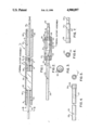
- FIG. 1 is a longitudinally sectional view of a heating element assembly of this invention
- FIG. 2 is a view in side elevation partly broken away and partly in section of the terminal pin and thermal switch assembly shown in FIG. 1;
- FIG. 3 is a view in end elevation taken along the line 3--3 of FIG. 1;
- FIG. 4 is a view in side elevation, shortened and somewhat enlarged, of a part of the terminal pin
- FIG. 5 is a view in end elevation looking from right to left of FIG. 4;
- FIG. 6 is a view in end elevation viewed from left to right of FIG. 7;
- FIG. 7 is a view in side elevation of another part of the terminal pin.
- reference numeral 1 indicates a completed assembly, ready for mounting or for bending into a desired shape, as in the water heater immerson heating element shown in U.S. Pat. No. 4,687,905.
- the heating assembly 1 has a sheath 5, within which is a conventional resistance element 10, a terminal pin 20, made in two parts, and a thermal cutoff assembly 30 therein.
- the sheath 5 has a rolled channel 6, producing an internal annular shoulder 7, near a thermal cutoff end of the sheath, which terminates in an opening 9.
- the terminal pin 20 has an inner part 21 with a reduced inner end 22 and an outer end 23 within which a blind passage 24 extends axially to serve as a socket.
- the terminal pin also has an outer part 25 with an outer part inner end 26, in which a blind passage 27 extends axially to form a socket, and an outer part outer end 28.
- Each of the blind passages 24 and 27 opens toward the thermal cutoff assembly 30, and is surrounded at its open end by a collar 29 integral with the respective terminal pin part.
- the thermal cutoff assembly 30 includes a thermal switch or cutoff 31, with an inner lead 32 and an outer lead 34 projecting from opposite ends of the cutoff and alined axially.
- the thermal cutoff 31 of this embodiment has a conical inner end 33.
- the inner lead 32 is secured, by crimping of the pin, in the passage or socket 24 in intimate electric and thermal contact with the wall defining the passage.
- the pin part 21 is countersunk at the open mouth of the passage 24 in a configuration complementary to the configuration of the inner end 33 of the thermal cutoff 31, and the surface defining the countersink is in intimate thermal contact with the end surface of the thermal cutoff.
- the outer lead 34 is mounted in the passage or socket 27 in intimate electrical contact with the wall defining the passage 27.
- the cutoff assembly also includes a sleeve 35 mounted coaxially with the cutoff 31 but spaced radially therefrom.
- the sleeve 35 can be made of Kapton type H or F polyimide film or its equivalent, preferably transparent enough to permit the rated temperature on the body of the thermal cutoff to be visible.
- the ends of the sleeve 35 are closed by silicone bushings 36 and 37, each of which has a radially inwardly extending annular flange 38 abutting an outboard edge of the collar 29.
- the bushings 36 and 37 can also be color coded to indicate rated temperature.
- the conventional insulating material is generally magnesium oxide powder.
- the diameter of the bushing 50 is at least as great as the diameter of the sleeve 35.
- a fiber washer 45 mounted on the outer part 25 contiguous the outboard surface of the bushing 37 spaces the thermal cutoff from a ceramic bushing 40, and tends to insulate the cutoff thermally from the elements on the outboard side of the thermal cutoff.
- a silicone bushing 55 is also mounted on the pin section 25, outboard of the ceramic bushing 40, serving to seal the outer end of the sheath, and to hold the rest of the elements tightly between the open mouth and the shoulder 7.
- the sheath 5 has an opposite end 60, in which a conventional one piece terminal pin 61 is mounted in a silicone bushing 64. The other end of the resistance element is secured electrically and mechanically to the terminal pin 61.
- the thermal cutoff leads are inserted in the respective sockets of the two sections of the terminal pin and crimped securely therein.
- the sleeve 35 and bushings 36 and 37 are mounted, the ceramic bushing 50 is put into place, and one end of the resistance element 10 is secured to the reduced inner end 22 of the terminal pin.
- the other end of the resistance element is secured to the inner end of the terminal pin 61.
- the fiber washer 45, ceramic bushing 40 and silicon bushing 55 are mounted on the terminal pin 20, and the entire assembly is mounted through the open end 9.
- the sheath is now stood on end vertically with the outer end of the terminal 61 projecting from the end 60 of the sheath, and centered, and the pulverulent insulating material introduced through the length of the sheath from the bushing 50 to the bushing 64, in the conventional way.
- the bushing 64 is put into place, and the sheath is rolled to compact the insulating material.
- the thermal cutoff assembly is protected against damage by the various bushings on either side of the thermal cutoff.
- the heat conducted by the terminal pin part 21 to the end of the thermal cutoff and the lead 32, together with the heat conducted by the sheath itself to the area in which the thermal cutoff is positioned within the sheath has been found to be sufficient to activate the thermal cutoff under conditions of overheating of the sheathed heating element, to give the desired protection.
- the thermal cutoff can be and preferably is of the type sold under the trademark MICROTEMP, series 9XXX, a product of Therm-O-Disc, Incorporated.
- the heating element assembly of this invention permits the use of a simple terminal block, with only two terminal pins projecting, while at the same time, it affords the protection desired.
- the thermal switch can be differently configured, and can even be made for over current protection. However, the latter does not pose the heretofore unsolved problems of the over temperature switch.
- the sheathed heating element can be made of any configuration, including a compound bend arrangement as illustrated in U.S. Pat. No. 4,687,905. These are merely illustrative.
Landscapes
- Resistance Heating (AREA)
Priority Applications (8)
| Application Number | Priority Date | Filing Date | Title |
|---|---|---|---|
| US07/273,291 US4900897A (en) | 1988-11-21 | 1988-11-21 | Sheathed electric heating element assembly |
| JP1258650A JP2903225B2 (ja) | 1988-11-21 | 1989-10-03 | 電気加熱素子組立体 |
| ES89630186T ES2054079T3 (es) | 1988-11-21 | 1989-10-05 | Conjunto elemento calentador electrico envainado. |
| DE68915124T DE68915124T2 (de) | 1988-11-21 | 1989-10-05 | Zusammenbau eines elektrischen Rohrheizkörpers. |
| EP89630186A EP0370941B1 (de) | 1988-11-21 | 1989-10-05 | Zusammenbau eines elektrischen Rohrheizkörpers |
| AT8989630186T ATE105456T1 (de) | 1988-11-21 | 1989-10-05 | Zusammenbau eines elektrischen rohrheizkoerpers. |
| AU43507/89A AU617546B2 (en) | 1988-11-21 | 1989-10-18 | Sheathed electric heating element assembly |
| KR1019890015416A KR0184855B1 (ko) | 1988-11-21 | 1989-10-26 | 금속피복된전기가열소자조립체 |
Applications Claiming Priority (1)
| Application Number | Priority Date | Filing Date | Title |
|---|---|---|---|
| US07/273,291 US4900897A (en) | 1988-11-21 | 1988-11-21 | Sheathed electric heating element assembly |
Publications (1)
| Publication Number | Publication Date |
|---|---|
| US4900897A true US4900897A (en) | 1990-02-13 |
Family
ID=23043323
Family Applications (1)
| Application Number | Title | Priority Date | Filing Date |
|---|---|---|---|
| US07/273,291 Expired - Lifetime US4900897A (en) | 1988-11-21 | 1988-11-21 | Sheathed electric heating element assembly |
Country Status (8)
| Country | Link |
|---|---|
| US (1) | US4900897A (de) |
| EP (1) | EP0370941B1 (de) |
| JP (1) | JP2903225B2 (de) |
| KR (1) | KR0184855B1 (de) |
| AT (1) | ATE105456T1 (de) |
| AU (1) | AU617546B2 (de) |
| DE (1) | DE68915124T2 (de) |
| ES (1) | ES2054079T3 (de) |
Cited By (11)
| Publication number | Priority date | Publication date | Assignee | Title |
|---|---|---|---|---|
| DE29707829U1 (de) * | 1997-05-01 | 1997-07-10 | Tovarna Elektrotermicnih Aparatov Eta Cerkno D.O.O., Cerkno | Rohrheizkörper mit eingebauter Überhitzungssicherung |
| US6111232A (en) * | 1995-09-01 | 2000-08-29 | Champion International Corporation | Recovery boiler smelt spout |
| RU2198447C2 (ru) * | 2001-03-01 | 2003-02-10 | Оао "Тэн" | Термовыключатель трубчатого электронагревателя |
| RU2237383C2 (ru) * | 2001-03-01 | 2004-09-27 | Оао "Тэн" | Термовыключатель тэна (трубчатого электронагревателя) |
| RU2246186C1 (ru) * | 2003-08-27 | 2005-02-10 | Котов Владимир Иванович | Электрический нагревательный элемент |
| RU2286653C1 (ru) * | 2005-04-12 | 2006-10-27 | Государственное образовательное учреждение высшего профессионального образования "Тверской государственный технический университет" | Трубчатый электронагреватель |
| US20080175572A1 (en) * | 2007-01-19 | 2008-07-24 | Barnes Ronald R | Heating element for appliance |
| RU2371887C1 (ru) * | 2008-04-14 | 2009-10-27 | Общество с ограниченной ответственностью "СагБар" | Способ изготовления трубчатого электронагревателя |
| US20190074112A1 (en) * | 2017-09-05 | 2019-03-07 | Hyundai Motor Company | Sheath heater |
| US10625562B2 (en) * | 2017-08-31 | 2020-04-21 | Hyundai Motor Company | Cooling water heating apparatus for electric vehicle |
| USD906383S1 (en) * | 2018-08-17 | 2020-12-29 | Hotset Gmbh | Electrical heater for injection-molding machine |
Families Citing this family (5)
| Publication number | Priority date | Publication date | Assignee | Title |
|---|---|---|---|---|
| GB9113581D0 (en) * | 1991-06-24 | 1991-08-14 | Sheathed Heating Elements Ltd | Electric element assembly |
| FR2681496A1 (fr) * | 1991-09-17 | 1993-03-19 | Vulcanic | Elements chauffants blindes a alimentation electrique, et procede de fabrication de tels elements. |
| KR101509222B1 (ko) * | 2013-11-06 | 2015-04-07 | 삼회산업 (주) | 캐스크(cask) 열차폐 성능 테스트용 히터 어셈블리 및 히터 어셈블리 |
| CH711968A1 (de) | 2015-12-28 | 2017-06-30 | C3 Casting Competence Center Gmbh | Durchlauferhitzer. |
| KR20210020246A (ko) | 2019-08-14 | 2021-02-24 | 권종철 | 히팅 엘리먼트 및 그 제조방법 |
Citations (6)
| Publication number | Priority date | Publication date | Assignee | Title |
|---|---|---|---|---|
| US1911063A (en) * | 1929-11-30 | 1933-05-23 | Gen Electric | Electrical heating unit |
| US2854556A (en) * | 1954-07-26 | 1958-09-30 | Wiegand Co Edwin L | Sheathed electric heater and method of making the same |
| US4156128A (en) * | 1977-03-18 | 1979-05-22 | Liquifry Company Limited | Electrical heater |
| GB2098436A (en) * | 1981-05-07 | 1982-11-17 | Ti Russell Hobbs Ltd | Electrical heating element |
| US4390776A (en) * | 1982-03-01 | 1983-06-28 | Yane Daryl J | Immersion heater |
| US4697069A (en) * | 1983-08-22 | 1987-09-29 | Ingo Bleckmann | Tubular heater with an overload safety means |
Family Cites Families (1)
| Publication number | Priority date | Publication date | Assignee | Title |
|---|---|---|---|---|
| WO1982004171A1 (fr) * | 1981-05-18 | 1982-11-25 | Naruo Noboru | Element chauffant blinde et procede de fabrication de celui-ci |
-
1988
- 1988-11-21 US US07/273,291 patent/US4900897A/en not_active Expired - Lifetime
-
1989
- 1989-10-03 JP JP1258650A patent/JP2903225B2/ja not_active Expired - Fee Related
- 1989-10-05 EP EP89630186A patent/EP0370941B1/de not_active Revoked
- 1989-10-05 AT AT8989630186T patent/ATE105456T1/de not_active IP Right Cessation
- 1989-10-05 ES ES89630186T patent/ES2054079T3/es not_active Expired - Lifetime
- 1989-10-05 DE DE68915124T patent/DE68915124T2/de not_active Revoked
- 1989-10-18 AU AU43507/89A patent/AU617546B2/en not_active Ceased
- 1989-10-26 KR KR1019890015416A patent/KR0184855B1/ko not_active Expired - Fee Related
Patent Citations (6)
| Publication number | Priority date | Publication date | Assignee | Title |
|---|---|---|---|---|
| US1911063A (en) * | 1929-11-30 | 1933-05-23 | Gen Electric | Electrical heating unit |
| US2854556A (en) * | 1954-07-26 | 1958-09-30 | Wiegand Co Edwin L | Sheathed electric heater and method of making the same |
| US4156128A (en) * | 1977-03-18 | 1979-05-22 | Liquifry Company Limited | Electrical heater |
| GB2098436A (en) * | 1981-05-07 | 1982-11-17 | Ti Russell Hobbs Ltd | Electrical heating element |
| US4390776A (en) * | 1982-03-01 | 1983-06-28 | Yane Daryl J | Immersion heater |
| US4697069A (en) * | 1983-08-22 | 1987-09-29 | Ingo Bleckmann | Tubular heater with an overload safety means |
Cited By (13)
| Publication number | Priority date | Publication date | Assignee | Title |
|---|---|---|---|---|
| US6111232A (en) * | 1995-09-01 | 2000-08-29 | Champion International Corporation | Recovery boiler smelt spout |
| DE29707829U1 (de) * | 1997-05-01 | 1997-07-10 | Tovarna Elektrotermicnih Aparatov Eta Cerkno D.O.O., Cerkno | Rohrheizkörper mit eingebauter Überhitzungssicherung |
| RU2198447C2 (ru) * | 2001-03-01 | 2003-02-10 | Оао "Тэн" | Термовыключатель трубчатого электронагревателя |
| RU2237383C2 (ru) * | 2001-03-01 | 2004-09-27 | Оао "Тэн" | Термовыключатель тэна (трубчатого электронагревателя) |
| RU2246186C1 (ru) * | 2003-08-27 | 2005-02-10 | Котов Владимир Иванович | Электрический нагревательный элемент |
| RU2286653C1 (ru) * | 2005-04-12 | 2006-10-27 | Государственное образовательное учреждение высшего профессионального образования "Тверской государственный технический университет" | Трубчатый электронагреватель |
| US20080175572A1 (en) * | 2007-01-19 | 2008-07-24 | Barnes Ronald R | Heating element for appliance |
| US7949238B2 (en) * | 2007-01-19 | 2011-05-24 | Emerson Electric Co. | Heating element for appliance |
| RU2371887C1 (ru) * | 2008-04-14 | 2009-10-27 | Общество с ограниченной ответственностью "СагБар" | Способ изготовления трубчатого электронагревателя |
| US10625562B2 (en) * | 2017-08-31 | 2020-04-21 | Hyundai Motor Company | Cooling water heating apparatus for electric vehicle |
| US20190074112A1 (en) * | 2017-09-05 | 2019-03-07 | Hyundai Motor Company | Sheath heater |
| US10622121B2 (en) * | 2017-09-05 | 2020-04-14 | Hyundai Motor Company | Sheath heater |
| USD906383S1 (en) * | 2018-08-17 | 2020-12-29 | Hotset Gmbh | Electrical heater for injection-molding machine |
Also Published As
| Publication number | Publication date |
|---|---|
| DE68915124D1 (de) | 1994-06-09 |
| ATE105456T1 (de) | 1994-05-15 |
| DE68915124T2 (de) | 1994-09-29 |
| JPH02174088A (ja) | 1990-07-05 |
| JP2903225B2 (ja) | 1999-06-07 |
| EP0370941A3 (en) | 1990-08-08 |
| ES2054079T3 (es) | 1994-08-01 |
| AU617546B2 (en) | 1991-11-28 |
| KR900008898A (ko) | 1990-06-04 |
| AU4350789A (en) | 1990-05-24 |
| EP0370941A2 (de) | 1990-05-30 |
| KR0184855B1 (ko) | 1999-04-15 |
| EP0370941B1 (de) | 1994-05-04 |
Similar Documents
| Publication | Publication Date | Title |
|---|---|---|
| US4900897A (en) | Sheathed electric heating element assembly | |
| US5247158A (en) | Electrical heater | |
| US4848616A (en) | Electric immersion heating unit with readily removable and replaceable galvanic current control resistor | |
| US5667712A (en) | Expandable multi-segment band heater construction with improved electrical connection | |
| ES2009051A6 (es) | Microfusible del tipo para chip. | |
| US4156128A (en) | Electrical heater | |
| US2526251A (en) | Thermally responsive impedance unit | |
| CA1072616A (en) | Submersible thermostatically controlled heaters | |
| US4380001A (en) | Electric safety device | |
| NO921100D0 (no) | Sveisbare roerforbindelsesdeler, samt roerforbindelser utformet av slike deler | |
| US3102248A (en) | Electric heater assembly | |
| CA1299630C (en) | Sheathed electric heating element assembly | |
| EP0726693A1 (de) | Heizvorrichtung für Aquarium-Behälter | |
| KR930702869A (ko) | 전기 소자 어셈블리 | |
| US5288245A (en) | Electric cable terminal with built-in marking support | |
| JPS5956616A (ja) | グロ−プラグ | |
| JP2542146B2 (ja) | シ―ズヒ―タ | |
| US1756704A (en) | Electrical outlet device | |
| US5287080A (en) | Blown fuse indicator | |
| US5080610A (en) | Apparatus for fixing a halogen lamp | |
| JPH07226264A (ja) | ヒューズ付きアプライアンスプラグ | |
| JPH0533949A (ja) | 電気ストーブ | |
| GB2257341A (en) | Heat transfer from resistance element to thermal switch. | |
| JP2018129924A (ja) | 熱収縮チューブ及び熱収縮チューブ付き端子金具 | |
| US3150344A (en) | Sealed connection for heating elements and method of assembling |
Legal Events
| Date | Code | Title | Description |
|---|---|---|---|
| FEPP | Fee payment procedure |
Free format text: PAYOR NUMBER ASSIGNED (ORIGINAL EVENT CODE: ASPN); ENTITY STATUS OF PATENT OWNER: LARGE ENTITY |
|
| AS | Assignment |
Owner name: EMERSON ELECTRIC CO., A CORP. OF MO, MISSOURI Free format text: ASSIGNMENT OF ASSIGNORS INTEREST.;ASSIGNORS:CUNNINGHAM, DONALD M.;BARTELS, MARK A.;MARKUM, T. RANDALL;REEL/FRAME:005195/0786;SIGNING DATES FROM 19890629 TO 19890711 |
|
| STCF | Information on status: patent grant |
Free format text: PATENTED CASE |
|
| FPAY | Fee payment |
Year of fee payment: 4 |
|
| SULP | Surcharge for late payment | ||
| FPAY | Fee payment |
Year of fee payment: 8 |
|
| FPAY | Fee payment |
Year of fee payment: 12 |