US4900052A - Cross-country ski binding - Google Patents
Cross-country ski binding Download PDFInfo
- Publication number
- US4900052A US4900052A US07/122,857 US12285787A US4900052A US 4900052 A US4900052 A US 4900052A US 12285787 A US12285787 A US 12285787A US 4900052 A US4900052 A US 4900052A
- Authority
- US
- United States
- Prior art keywords
- pin
- boot
- binding according
- ski
- ski binding
- Prior art date
- Legal status (The legal status is an assumption and is not a legal conclusion. Google has not performed a legal analysis and makes no representation as to the accuracy of the status listed.)
- Expired - Fee Related
Links
Images
Classifications
-
- A—HUMAN NECESSITIES
- A63—SPORTS; GAMES; AMUSEMENTS
- A63C—SKATES; SKIS; ROLLER SKATES; DESIGN OR LAYOUT OF COURTS, RINKS OR THE LIKE
- A63C9/00—Ski bindings
- A63C9/20—Non-self-releasing bindings with special sole edge holders instead of toe-straps
Definitions
- the present invention relates to a cross-country ski binding, and particularly to a binding of a type adapted to cooperate with the front end of a ski boot.
- the ski binding of the present invention includes a rectilinear pin adapted to support the end of the boot equipped with means forming a guidance bearing for the pin adapted for rotation around an axis with respect to a ski.
- the ski binding of the present invention preferably includes means for retaining the end of the boot on the ski composed of a transverse member adapted to engage positioned beneath the end of the boot, and at least one arm adapted to extend laterally adjacent the end of the boot and to ensure the mounting of the transverse member for free rotation around the axis with respect to the means forming the bearing.
- a binding of the type described above is generally disclosed in French Application No. 2 399 856 with regard to FIGS. 10-13.
- French Application No. 2 399 856 provides an embodiment whereby the pin and retention means are made of a single element which is free to rotate with respect to the means forming the guidance bearing.
- the binding described in this document has, as a result, a simple structure, which is easy and economical to produce.
- the binding has a substantial disadvantage in that nothing is provided to ensure an elastic return of the boot and of the ski towards a relative position in which the boot rests substantially flat on the ski.
- Another disadvantage of such a binding is that it is difficult to maintain the ski in the track and that skating steps are not possible.
- the structure of the binding enhances the ability of the skier to keep the skis in their tracks and also permits skating steps to be easily performed by the skier.
- the binding of the invention has a pin mounted for rotation on the ski, which has at least one surface that is arranged to cooperate with a complementary surface on the sole of the boot so that the boot can rotate with the pin.
- the binding includes a return means which is arranged to cooperate with the pin in a manner so that as the pin rotates by virtue of the complementary surfaces rotation and urges the boot to a position in which the boot is substantially flat on the ski.
- the binding of the present invention also includes a retention means which is arranged to rotate with the pin from a first position wherein the retention means permits the boot to be placed upon the ski to a second position in which the retention means engages the upper surface of a boot to retain the boot on the ski.
- the retention means includes a pair of arms which, together with a transverse member, affix a front portion of the boot to the pin. This configuration permits the heel of the boot to pivot around the pin during cross-country skiing.
- the pin is journalled for rotation in a rib which is located along an upper longitudinal axis on the top surface of the ski. Projecting from either side of the rib are the respective complementary surfaces of the pin which engage respective surfaces of the front end of the boot.
- the return means which includes at least one compressible member that acts upon at least one of the surfaces of the pin to urge the pin and concomittantly the boot to the position in which the boot is substantially flat on the ski.
- a piston member which acts upon the surface of the pin is provided between the surface of the pin and the compressible member.
- the retention means includes a reinforcement member which, preferably, is concave upwardly for permitting the skier to effect rotation of the retention means to thereby permit the skier to disengage the boot from the binding.
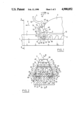
- FIG. 1 shows, in lateral elevation, a view of a binding according to the invention wherein the boot is inserted in the binding of the ski, the boot being retained by the binding resting flat on the ski;
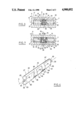
- FIG. 2 illustrates a front view, in cross section through a plane identified as II--II in FIG. 1 and transverse with respect to a longitudinal median plane of the ski;
- FIG. 3 illustrates a cross sectional view through plane III--III of FIG. 2, constituting a median longitudinal plane of the ski;
- FIG. 4 illustrates the pin of the binding, in a perspective view
- FIG. 5 illustrates the insertion or removal of the boot, in a view similar to that of FIG. 1;
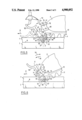
- FIG. 6 illustrates, in a view similar to that of FIG. 1, one position of the binding while, in the course of practicing cross-country skiing, the heel (not shown) of the boot is lifted with respect to the ski;
- FIG. 7 illustrates one view of the binding such as it appears in FIG. 6 in cross section through a plane identical to plane III--III of FIG. 2.
- the present invention is directed to a cross-country ski binding which is characterized in that a pin is freely mounted for rotation around an axis transverse to the ski, and has at least one radial engagement and removable affixation portion complementary in shape to the end projection of the boot and in that there is provided an elastic return means for the pin to urge rotation of the boot about the axis, with respect to the bearing means for the pin, towards a preferred position corresponding to a position in which the boot rests flat on the ski.
- This configuration tends to maintain the ski in the track, and skating steps become possible.
- the return of the boot to a position in which the boot rests substantially flat on the ski is particularly advantageous because the force is applied directly by the pin to the front end of the boot, without causing ratcheting of the transverse member of the retention means, which may have a certain elasticity, from the end projection of the boot.
- the binding according to the invention is of relatively simple construction, particularly when the arm of the retention means is mounted directly on the pin to be freely rotatable around the axis.
- the retention means includes a second arm adapted to extend laterally adjacent the front end of the boot opposite the first arm to define a U shape with the latter and the transverse member.
- the pin is likewise freely rotatable about the axis with respect to the second arm which, preferably, can be mounted directly on the pin, and be freely rotatable about the axis, in a manner similar to the first arm.
- the transverse member is thus advantageously freely rotatably mounted for rotation with the pin about the axis as well as with respect to the means forming the bearing, i.e., with respect to the ski.
- the radial engagement and removable affixation portion for the front end of the boot includes at least one flattened section of the pin, which is complementary to an opening in the end projection of the boot.
- the pin can include at least one flattened region, and a compressible elastic means can be located in the means which forms a bearing and engage this flattened section.
- the means which forms a bearing and/or the compressible elastic means is located within a rib mounted on the ski so as to shelter as much as possible the means with respect to the snow.
- the portion of the binding thus constructed that projects from the ski is therefore limited to the retention means which reduces the dangers of accumulation of snow which would otherwise resist the operation of the binding.
- the rib can either be integrally formed with the ski or be applied thereto, and can likewise either be positioned only in the zone of the binding or extend in front and/or in the rear thereof, according to a technique known in itself in the ski manufacturing field.
- FIGS. 1, 2, 5 and 6 illustrate a longitudinal ski 1 with respect to which a boot 2 is or can be journalled around a transverse axis 3, perpendicular to a median longitudinal plane 4 of the ski, by means of a binding 5 according to the invention.
- ski 1 rests substantially flat and horizontally on the ground and reference will be made to such a position.
- reference will be made to a normal longitudinal direction 6 of displacement of the ski, from rear to front.
- the indications of the level and orientation which will appear below are in no way limiting with respect to the position in which a binding according to the invention can be utilized, and should be considered only as relative position indicators of the different elements described.
- Ski 1 illustrated by way of non-limiting example is of the type including an upper longitudinal rib 7 extending for the major portion of the length of the ski and forming an integral portion therewith, between two longitudinal surfaces 8 and 9 of the upper surface which, in an area localized in the immediate proximity of binding 5 can be considered as planar and coplanar.
- boot 2 has a smooth sole having a longitudinal groove 11 therein, which is continuous and is adapted to mate with rib 7 to allow boot 2 to occupy the position illustrated in FIGS. 1 and 2, in which sole 10 rests flat on surfaces 8 and 9 of the upper surface of ski 1, respectively, on both sides of rib 7.
- the rib 7 can, for example, be reduced to a localized projection in the immediate vicinity of binding 5 and, for example, be applied to the ski with the sole purpose of ensuring the mounting of binding 5 on the ski.
- rib 7 whose cross section in this case is, for example, trapezoidal and converges upwardly as seen in FIG. 2, where the rib or projection 7 has, at least in a localized fashion with respect to binding 5, two side surfaces 12 and 13 symmetrical to one another with respect to the longitudinal median plane 4, mutually connected on the top to an upper surface 14, for example planar and perpendicular to plane 4, while the side surfaces 12 and 13 are connected on the bottom to the upper surface 8 and to the upper surface 9, respectively.
- Axis 3 is secant to surfaces 12 and 13.
- a bore 15 having a peripheral cylindrical surface of revolution 16 around axis 3 with a diameter such that the bore 15 is situated between surfaces 8 and 9 of the upper surface of ski 1, on the one hand, and the upper surface 14 on the other hand.
- rib 7 or the localized projection in addition to the transverse bore 15, rib 7 or the localized projection, is a longitudinal bore 17 defining a peripheral cylindrical surface of revolution 18 around a longitudinal axis 19.
- Bore 17 is situated in the longitudinal median plane 4 of the ski, horizontally if one refers to the position illustrated, and is perpendicular to axis 3 such that bore 15 opens into bore 17 within rib 7, or the localized projection.
- the diameter of surface 18 is greater than that of surface 16 remaining not reach the upper surface 14.
- identical diameters can likewise be adopted, as well as a diameter of surface 18 less than that of surface 16.
- bore 17 is closed by end surfaces 20 and 21 which, e.g., are planar and perpendicular to axis 19.
- end surfaces 20 and 21 which, e.g., are planar and perpendicular to axis 19.
- On these end surfaces 20 and 21 rest respective ends of helical springs 22 and 23 along axis 19 which are positioned in bore 17 respectively on both sides of axis 3.
- the other ends of springs 22 and 23 rest against respective pistons 24 and 25 which are flat and perpendicular to axis 19, and are slidably guided along axis 19 within bore 17. It may be desirable to have springs 22 and 23 adjustably tensioned by virtue of means not shown, but which would be within the capability of one of ordinary skill in the art.
- pin 27 Between pistons 24 and 25 is interposed a central section 26 of rectilinear pin 27 which is engaged along axis 3 in bore 15, and which is rotatable about axis 3 with respect to rib or the localized projection 7.
- pin 27 has, respectively on both sides of its central section 26, two intermediate sections 28 and 29 which are defined by respective surfaces 30 and 31 which are cylinders of revolution around axis 3 with a diameter substantially identical to that of surface 16 of bore 15.
- the intermediate section 28 thus runs through bore 15 from the intersection thereof with bore 17 to surface 12 of rib or the localized projection 7.
- the intermediate section 29 runs through bore 15 from the intersection thereof with bore 17 to surface 13.
- the central section 26 is only partially defined by a cylindrical surface of revolution around axis 3 with a diameter substantially identical to that of bore 15, i.e., by two surfaces 32 and 33 which are located in diametrically defined by two planar surfaces 34 and 35 which are parallel and symmetrical to one another.
- Surfaces 34 and 35 are connected to the respective cylindrical surfaces 30 and 31 of the intermediate sections 28 and 29 of pin 27 by planar surfaces 36 and 37 which are perpendicular to axis 3 and are parallel to the longitudinal median plane 4 of the ski.
- Surfaces 34 and 35 are symmetrical to one another with respect to plane 4 and have the same length along axis 3 which corresponds substantially to the diameter of bore 17 in a manner so as to be flush with surface 18 along axis 3.
- pin 27 has, respectively on each side of rib or projection 7, two end surfaces 38 and 39 which are symmetrical to one another with respect to plane 4, and which are positioned, respectively, above surfaces 8 and 9.
- pin 27 has a respective end section 80 or 81.
- end section 80 or 81 When either end section is seen in cross section through a plane perpendicular to axis 3, it is at each point identical to that of section 26 through such a plane and, for example, through the longitudinal median plane 4 of the ski.
- two partial cylinder portions 82 and 83 are located in diametrically opposed positions with respect to axis 3 and are defined by a cylindrical surface of revolution around axis 3 and have the same diameter as surfaces 30 and 31 of the intermediate sections 28 and 29 as well as the surfaces 32 and 33 of the central section 26.
- the end section 80 of the pin 27 is defined by two planar surfaces 84 and 85 which are parallel to one another and are symmetrical to one another with respect to axis 3 and preferably coplanar, respectively, with surfaces 34 and 35 of central section 26 and define two flattened sections on the end section 80.
- These two surfaces 84 and 85 are connected to the cylindrical surface 30 of the intermediate section 28 of pin 27 by respective planar surfaces 86 which are perpendicular to axis 3 and which coincide substantially with surface 12 of rib or projection 7.
- end section 81 of pin 27 is defined, between two surfaces 87 and 88 which are diametrically opposed and symmetrical to one another with respect to axis 3, as having a cylinder of revolution around axis 3 and a diameter identical to that of surfaces 30 and 31 and of surfaces 32, 33, 82, 83 by two planar surfaces 89 and 90 which are parallel and symmetrical to one another with respect to axis 3, and respectively coplanar with the planar surfaces 84 and 85 to define two flattened portions and 90 are connected to cylindrical surface 31 of intermediate section 29 of pin 27 by respective planar surfaces 91, which are coplanar and perpendicular to axis 3 coinciding substantially with surface 13 of rib or projection 7.
- pin 27 is likewise defined by planar end surfaces 92 and 93 which are perpendicular to axis 3. Each surface has a respective cylindrical swivel 94, 95 projecting therefrom and preferably is formed as one piece with pin 27.
- the pin 27 carries a U-shaped stirrup 40 comprising two arms 41 and 42 connected by a rectilinear transverse member 43, which is parallel to axis 3, at a level above that of axis 3 in normal conditions of use.
- arms 41 and 42 of stirrup 40 are positioned on either side of rib or projection 7.
- Each of the arms 41 and 42 has a lower end portion, respectively 44 and 45, each of which contains a bore co-axial with axis 3 within which respective ones of swivels 94 and 95 engage.
- the two arms 41 and 42 near the respective end portions 44 and 45, have planes parallel to the longitudinal median plane 4 of the ski and rest respectively against end surfaces 92 and 93 of pin 27, and are freely rotatable around axis 3.
- the two arms 41 and 42 are bent, respectively at 46 and 47, beyond which they are planar and converge upwardly symmetrically toward and with respect to plane 4.
- the two arms 41 and 42 extend beyond transverse member 43 to respective upper end portions 48 and 49 where they are connected to a reinforcement member 50 which has a concavity directed upwardly and which is adapted to receive the point of a ski pole during removal of the boot,
- a reinforcement member 50 which has a concavity directed upwardly and which is adapted to receive the point of a ski pole during removal of the boot.
- the two arms 41 and 42 are formed as a single piece member 50, however other embodiments are possible without going beyond the scope of the present invention.
- arms 41 and 42 can have different shapes from the shape described. For example, they could be planar and parallel with respect to plane 4, from the lower end portions 44 and 45 to the upper end portions 48 and 49.
- transverse 43 can be constituted by reinforcement member 50 which is carefully constructed to perform the function of transverse member 43 and which will be described below.
- sole 10 of boot 2 has a front end projection 51 which, for reasons of simplicity, will be described with reference to the position of the boot illustrated in FIGS. 1 and 2.
- end projection 51 which, for the most part is situated above rib or projection 7 and engaged within stirrup 40, between transverse member 43 of the latter, arms 41 and 42 and the upper surface 14 of rib or projection 7 is subdivided towards the front and bottom into two portions 52 and 53 which are symmetrical to one another with respect to the longitudinal median plane 4 of ski 1 and overlap respectively between surface 12 of rib or projection 7 and arm 41, and between surface 13 of rib or projection 7 and the arm 42 of stirrup 40, to rest respectively on the end section 80 of pin 27 and on the end section 81 of pin 27, outside of rib or projection 7.
- the two portions 52 and 53 have facing, planar surfaces 54 and 55 which are parallel and symmetrical to one another with respect to plane 4.
- Surfaces 54 and 55 are spaced by a distance corresponding substantially to the spacing of surfaces 12 and 13 perpendicularly to plane 4 as well as the spacing surfaces 86 and 91 of pin 27 perpendicularly to plane 4, in a manner so as to establish sliding contact of surfaces 54 and 55 with surfaces 12 and 86, respectively, and with surfaces 13 constitute extensions of side surfaces of groove 11 of sole 10.
- End projection 51 includes lateral surfaces 56 and 57 which have a shape chosen to permit, respectively between surface 56 and arm 41 and between surface 57 and arm 42, free movement as shown at locations 58 and 59. This movement between stirrup 40 and end projection 51 is necessary for insertion and removal of the boot and will be described below.
- surfaces 54 and 55 are connected respectively to surfaces 56 and 57 by side surfaces 60 and 61 which have openings therein respectively 62 and 63 which open downwardly and open respectively onto surfaces 54 and 56 and in surfaces 55 and 57.
- each of openings 62 and 63 is concentric with axis 64 which axis coincides with axis 3 in the position illustrated in FIG. 1. More specifically, each of openings 62 and 63 is defined by a peripheral surface having a top portion such as 65 in the shape of a cylinder of revolution around axis 64 and which is similar and complementary to that of surfaces 82 and 87 of the end sections 80 and 81 of pin 27 such that, when the boot occupies the position illustrated in FIG. 1, the top portion such as 65 mates respectively with the portion of surface 82 of section 80 and the portion of surface 87 of section 81 on each of portions 82 and 87 situated above the horizontal plane 66 passing through axes 3 and 64.
- Each of the peripheral surfaces of boot 2, such as 65 extends downwardly below plane 66 to the rear of axis 64, and is connected to a surface such as 67 which is planar and perpendicular to plane 66, which is then connected towards the bottom to the lower surface such as 68 of the sole, which is adapted to rest on the upper surface such as 8 in the position illustrated in FIG. 1.
- a surface such as 69 which is planar and perpendicular to plane 66 is connected at its lower end to a planar surface such as 70 which is parallel to plane 66, and is located between plane 66 and the lower surface of the sole such as 68.
- the surfaces such as 67 and 69 which are parallel to one another and placed in symmetrical positions with respect to axis 64, are spaced by a distance corresponding substantially to the spacing of the flattened surfaces 84 and 85 of section 80 of pin 27 and to that of the flattened surfaces 89 and 90 of the section 81 of the pin such that, in the position illustrated in FIG. 1, the surfaces such as 67 of openings 62 and 63 are flattened against the flattened surfaces 84 and 89, respectively, and the surfaces such as 69 of openings 62 and 63 are flattened against the flattened surfaces 85 and 90 respectively.
- This configuration ensures a fixed engagement between the end projection 51 of boot 2 and pin 27 to permit rotation of the boot around axis 3, with respect to ski 1.
- the surfaces such as 70 are connected to respective front surfaces 71 and 72 of portions 52 and 53, which front surfaces in the example illustrated are planar but which can have any shape adapted so as not to interfere with the concurrent pivoting movement of boot 2 and stirrup 40 around axes 64 and 3, described below.
- end projection 51 is defined by a front surface 73 whose shape is adapted so as not to interfere with such movements and, for example, is planar with an orientation appropriately selected for this purpose.
- the front respective surfaces 71 and 72 of portions 52 and 53 as well as surfaces 54, 55, 56 and 57 and the front surface 73 are connected to an upper surface 74 of end projection 51, which surface 74 is for example planar and parallel to the axis 64 and, in the position illustrated in FIG. 1, ascends towards the rear in a manner so as to have a front end 75 spaced with respect to axes 3 and 64 less than the spacing of the transverse member 43 from axis 3, and a rear end 76 spaced with respect to axes 3 and 64 greater than the spacing of the transverse member 43 from axis 3.
- upper surface 74 is provided with a rectilinear groove 77 which is parallel to axis 64 and transverse member 43 is engaged in the position illustrated in FIG. 1 due to the elasticity of end projection 51.
- This engagement can be effected by the inherent elasticity of stirrup 40 and/or end projection 51.
- Groove 77 is spaced from axis 64 by a distance at least equal to the distance separating transverse member 43 from axis 3. This engagement ensures the retention of end projection 51 by way of openings 62 and 63 on end sections 80 and 81 of pin 27.
- binding 5 which has just been described is as follows.
- the skier engages, by a descending movement of boot 2 towards ski 1, openings 62 and 63 respectively with sections 80 and 81 of pin 27, between arms 41 and 42 of stirrup 40, resulting in a sliding of surfaces such as 67 against flat surfaces 84 and 89 and of surfaces such as 69 against flat surfaces 85 and 90 along a radial direction with respect to axis 3 until axes 64 and 3 become co-axial.
- the portions such as 65 of the peripheral surfaces of the two openings 62 and 63 thus tightly mate with the respective upper surfaces 82 and 87 of the end sections 80 and 81 of pin 27 without the possibility of relative rotation around co-axial axes 64 and 3 and without the possibility of relative parallel displacement of axis 3 by virtue of the fact that the surfaces 54 and 55 are respectively applied against the surfaces 12 and 86 and against the surfaces 13 and 91.
- stirrup 40 remains engaged with end projection 51 and rotatably moves therewith with respect to the ski around coaxial axes 64 and 3, by ensuring the retention of end projection 51 on end sections 80 and 81 of pin 27 by means of openings 62 and 63.
- the engagement of surfaces 54 and 55 against surfaces 12 and 13 furthermore ensures the lateral retention of boot 2 with respect to the ski.
- end projection 51 remains affixed to pin 27 with respect to rotation around axis 3 with respect to ski 1, so that pin 27 assumes an orientation like that illustrated in FIG. 7.
- Springs 22 and 23 become more compressed and, via pin 27, create a return moment to urge the boot 2 towards the position illustrated in FIG. 1. This return moment increases in proportion to the increase of rotation of boot 2 with respect to ski 1 in direction 78.
- stirrup 40 When the skier desires to remove his boot, he positions it flat on the ski, as is illustrated in FIG. 1, which allows stirrup 40 to reassume the position illustrated and the pin 27 to reassume the orientation illustrated in FIG. 3.
- the skier By applying a force through the point of his pole in direction 78 to reinforcement member 50, as is illustrated in FIG. 5, the skier can cause a pivoting of stirrup 40 until the surface 74 of end projection 51 is freed from transverse member 43, which then permits him to lift his foot to disengage openings 62 and 63 from end sections 28 and 29 of pin 27.
- the stirrup falls freely in direction 78 towards the position illustrated in dashed lines in FIG. 5 as soon as transverse member 43 is disengaged from groove 77.
Landscapes
- Footwear And Its Accessory, Manufacturing Method And Apparatuses (AREA)
- Non-Silver Salt Photosensitive Materials And Non-Silver Salt Photography (AREA)
Applications Claiming Priority (2)
| Application Number | Priority Date | Filing Date | Title |
|---|---|---|---|
| FR8615946A FR2606658B1 (fr) | 1986-11-17 | 1986-11-17 | Fixation pour ski de fond |
| FR8615946 | 1986-11-17 |
Publications (1)
| Publication Number | Publication Date |
|---|---|
| US4900052A true US4900052A (en) | 1990-02-13 |
Family
ID=9340873
Family Applications (1)
| Application Number | Title | Priority Date | Filing Date |
|---|---|---|---|
| US07/122,857 Expired - Fee Related US4900052A (en) | 1986-11-17 | 1987-11-17 | Cross-country ski binding |
Country Status (7)
| Country | Link |
|---|---|
| US (1) | US4900052A (fr) |
| AT (1) | AT391091B (fr) |
| DE (1) | DE3738206C2 (fr) |
| FI (1) | FI874938A (fr) |
| FR (1) | FR2606658B1 (fr) |
| NO (1) | NO162181C (fr) |
| SE (1) | SE8704490L (fr) |
Cited By (1)
| Publication number | Priority date | Publication date | Assignee | Title |
|---|---|---|---|---|
| US9138630B2 (en) | 2013-02-01 | 2015-09-22 | Marker Deutschland Gmbh | Heel retainer with auxiliary lever |
Families Citing this family (1)
| Publication number | Priority date | Publication date | Assignee | Title |
|---|---|---|---|---|
| US6374517B2 (en) * | 1994-04-29 | 2002-04-23 | Salomon S.A. | Sole for a sport boot and a sport boot including such sole |
Citations (9)
| Publication number | Priority date | Publication date | Assignee | Title |
|---|---|---|---|---|
| US2649306A (en) * | 1951-07-13 | 1953-08-18 | Anderson C Hilding | Ski harness |
| US3003777A (en) * | 1951-07-13 | 1961-10-10 | Anderson C Hilding | Ski binding |
| US4083578A (en) * | 1976-12-02 | 1978-04-11 | Moog Inc. | Toe clip for a ski binding |
| FR2399856A1 (fr) * | 1977-08-09 | 1979-03-09 | Polyair Produkt Design Gmbh | Fixation pour ski de fond |
| FR2424037A1 (fr) * | 1978-04-28 | 1979-11-23 | Salomon & Fils F | |
| FR2439602A1 (fr) * | 1978-10-24 | 1980-05-23 | Salomon & Fils F | Dispositif de maintien d'une extremite d'une chaussure sur un ski, notamment fixation pour ski de fond ou de randonnee |
| EP0167462A1 (fr) * | 1984-05-29 | 1986-01-08 | Skis Rossignol S.A. | Ensemble constitué d'un ski de fond, d'une fixation de ski de fond, et d'une chaussure de ski de fond |
| US4647064A (en) * | 1983-02-09 | 1987-03-03 | Salomon S.A. | Ski binding for use in cross-country or mountaineer skiing |
| FR2591120A1 (fr) * | 1985-12-05 | 1987-06-12 | Rossignol Sa | Dispositif destine a la fixation d'une chaussure sur un ski de fond. |
Family Cites Families (1)
| Publication number | Priority date | Publication date | Assignee | Title |
|---|---|---|---|---|
| FR2577428B1 (fr) * | 1985-02-19 | 1987-10-30 | Rossignol Sa | Fixation de ski de fond |
-
1986
- 1986-11-17 FR FR8615946A patent/FR2606658B1/fr not_active Expired - Fee Related
-
1987
- 1987-11-09 FI FI874938A patent/FI874938A/fi not_active IP Right Cessation
- 1987-11-10 AT AT2973/87A patent/AT391091B/de not_active IP Right Cessation
- 1987-11-10 DE DE3738206A patent/DE3738206C2/de not_active Expired - Fee Related
- 1987-11-10 NO NO874665A patent/NO162181C/no unknown
- 1987-11-16 SE SE8704490A patent/SE8704490L/ not_active Application Discontinuation
- 1987-11-17 US US07/122,857 patent/US4900052A/en not_active Expired - Fee Related
Patent Citations (13)
| Publication number | Priority date | Publication date | Assignee | Title |
|---|---|---|---|---|
| US2649306A (en) * | 1951-07-13 | 1953-08-18 | Anderson C Hilding | Ski harness |
| US3003777A (en) * | 1951-07-13 | 1961-10-10 | Anderson C Hilding | Ski binding |
| US4083578A (en) * | 1976-12-02 | 1978-04-11 | Moog Inc. | Toe clip for a ski binding |
| US4266805A (en) * | 1977-08-09 | 1981-05-12 | Polyair Produkt Design Gesellschaft M.B.H. | Binding for cross country skis |
| FR2399856A1 (fr) * | 1977-08-09 | 1979-03-09 | Polyair Produkt Design Gmbh | Fixation pour ski de fond |
| FR2424037A1 (fr) * | 1978-04-28 | 1979-11-23 | Salomon & Fils F | |
| US4402525A (en) * | 1978-04-28 | 1983-09-06 | Etablissements Francois Salomom Et Fils Chemin De La Prairie Prolonge | Ski safety binding |
| FR2439602A1 (fr) * | 1978-10-24 | 1980-05-23 | Salomon & Fils F | Dispositif de maintien d'une extremite d'une chaussure sur un ski, notamment fixation pour ski de fond ou de randonnee |
| US4309833A (en) * | 1978-10-24 | 1982-01-12 | Salomon Georges P J | Ski binding and boot |
| US4647064A (en) * | 1983-02-09 | 1987-03-03 | Salomon S.A. | Ski binding for use in cross-country or mountaineer skiing |
| EP0167462A1 (fr) * | 1984-05-29 | 1986-01-08 | Skis Rossignol S.A. | Ensemble constitué d'un ski de fond, d'une fixation de ski de fond, et d'une chaussure de ski de fond |
| US4714267A (en) * | 1984-05-29 | 1987-12-22 | Skis Rossignol S.A. | Cross country ski assembly |
| FR2591120A1 (fr) * | 1985-12-05 | 1987-06-12 | Rossignol Sa | Dispositif destine a la fixation d'une chaussure sur un ski de fond. |
Cited By (2)
| Publication number | Priority date | Publication date | Assignee | Title |
|---|---|---|---|---|
| US9138630B2 (en) | 2013-02-01 | 2015-09-22 | Marker Deutschland Gmbh | Heel retainer with auxiliary lever |
| US9457259B2 (en) * | 2013-02-01 | 2016-10-04 | Marker Deutschland Gmbh | Heel retainer with auxiliary lever |
Also Published As
| Publication number | Publication date |
|---|---|
| ATA297387A (de) | 1990-02-15 |
| NO162181B (no) | 1989-08-14 |
| SE8704490L (sv) | 1988-05-18 |
| DE3738206C2 (de) | 1996-12-12 |
| FR2606658B1 (fr) | 1990-08-17 |
| FI874938A (fi) | 1988-05-18 |
| FR2606658A1 (fr) | 1988-05-20 |
| SE8704490D0 (sv) | 1987-11-16 |
| NO874665D0 (no) | 1987-11-10 |
| NO874665L (no) | 1988-05-18 |
| FI874938A0 (fi) | 1987-11-09 |
| AT391091B (de) | 1990-08-10 |
| DE3738206A1 (de) | 1988-05-19 |
| NO162181C (no) | 1989-11-22 |
Similar Documents
| Publication | Publication Date | Title |
|---|---|---|
| US4309833A (en) | Ski binding and boot | |
| US5944337A (en) | Automatic binding device | |
| US6209903B1 (en) | Apparatus for attaching a gliding element to a shoe | |
| US5664797A (en) | Cross-country ski binding and complementary cross-country ski boot | |
| US7422227B2 (en) | Ski binding for cross country or telemark ski | |
| US4190264A (en) | Safety ski binding | |
| US4679815A (en) | Safety ski binding | |
| JPH07313655A (ja) | とりわけアルペンスキー板のようなスキー板の圧力の自然な配分を変更するためのインターフェイス装置 | |
| US5085454A (en) | Cross-country ski binding | |
| US4278269A (en) | Combined ski boot and safety binding | |
| US3433494A (en) | Brake attachment for ski | |
| US4900052A (en) | Cross-country ski binding | |
| US5566966A (en) | Device for modifying the pressure distribution of a ski along its sliding surface | |
| US4927168A (en) | Cross-country ski binding | |
| US6923465B2 (en) | Heel shim and lifter for ski mountaineering | |
| US3797843A (en) | Device for securing a boot to a base | |
| EP0236417A1 (fr) | Fixation de ski pour ski de fond alpin avec articulation physiologique | |
| US4863186A (en) | Safety binding | |
| US5695211A (en) | Binding element for alpine skis | |
| US4468048A (en) | Safety ski binding | |
| US4909532A (en) | Cross-country ski binding | |
| US4684146A (en) | Heel holder | |
| US5224729A (en) | Cross-country ski binding | |
| US4961591A (en) | Lateral guidance apparatus for a cross-country ski boot | |
| JPH0852004A (ja) | 特にスキー実施用の靴とその保持具のセット |
Legal Events
| Date | Code | Title | Description |
|---|---|---|---|
| AS | Assignment |
Owner name: SALOMON S.A., SIEGE SOCIAL DE METZ-TESSY, B.P. 454 Free format text: ASSIGNMENT OF ASSIGNORS INTEREST.;ASSIGNORS:PROVENCE, MARC;ROUSSET, DIDIER;DUNAND, JOSIANE;REEL/FRAME:004876/0655 Effective date: 19871223 Owner name: SALOMON S.A., A CORP. OF FRANCE, FRANCE Free format text: ASSIGNMENT OF ASSIGNORS INTEREST;ASSIGNORS:PROVENCE, MARC;ROUSSET, DIDIER;DUNAND, JOSIANE;REEL/FRAME:004876/0655 Effective date: 19871223 |
|
| CC | Certificate of correction | ||
| FPAY | Fee payment |
Year of fee payment: 4 |
|
| REMI | Maintenance fee reminder mailed | ||
| LAPS | Lapse for failure to pay maintenance fees | ||
| FP | Lapsed due to failure to pay maintenance fee |
Effective date: 19980218 |
|
| STCH | Information on status: patent discontinuation |
Free format text: PATENT EXPIRED DUE TO NONPAYMENT OF MAINTENANCE FEES UNDER 37 CFR 1.362 |