US4899791A - Liquid level control apparatus - Google Patents
Liquid level control apparatus Download PDFInfo
- Publication number
- US4899791A US4899791A US07/305,072 US30507289A US4899791A US 4899791 A US4899791 A US 4899791A US 30507289 A US30507289 A US 30507289A US 4899791 A US4899791 A US 4899791A
- Authority
- US
- United States
- Prior art keywords
- shaft
- liquid level
- housing
- support arm
- level controller
- Prior art date
- Legal status (The legal status is an assumption and is not a legal conclusion. Google has not performed a legal analysis and makes no representation as to the accuracy of the status listed.)
- Expired - Fee Related
Links
Images
Classifications
-
- B—PERFORMING OPERATIONS; TRANSPORTING
- B67—OPENING, CLOSING OR CLEANING BOTTLES, JARS OR SIMILAR CONTAINERS; LIQUID HANDLING
- B67C—CLEANING, FILLING WITH LIQUIDS OR SEMILIQUIDS, OR EMPTYING, OF BOTTLES, JARS, CANS, CASKS, BARRELS, OR SIMILAR CONTAINERS, NOT OTHERWISE PROVIDED FOR; FUNNELS
- B67C3/00—Bottling liquids or semiliquids; Filling jars or cans with liquids or semiliquids using bottling or like apparatus; Filling casks or barrels with liquids or semiliquids
- B67C3/02—Bottling liquids or semiliquids; Filling jars or cans with liquids or semiliquids using bottling or like apparatus
- B67C3/22—Details
- B67C3/28—Flow-control devices, e.g. using valves
- B67C3/282—Flow-control devices, e.g. using valves related to filling level control
-
- B—PERFORMING OPERATIONS; TRANSPORTING
- B67—OPENING, CLOSING OR CLEANING BOTTLES, JARS OR SIMILAR CONTAINERS; LIQUID HANDLING
- B67C—CLEANING, FILLING WITH LIQUIDS OR SEMILIQUIDS, OR EMPTYING, OF BOTTLES, JARS, CANS, CASKS, BARRELS, OR SIMILAR CONTAINERS, NOT OTHERWISE PROVIDED FOR; FUNNELS
- B67C3/00—Bottling liquids or semiliquids; Filling jars or cans with liquids or semiliquids using bottling or like apparatus; Filling casks or barrels with liquids or semiliquids
- B67C3/02—Bottling liquids or semiliquids; Filling jars or cans with liquids or semiliquids using bottling or like apparatus
- B67C3/22—Details
- B67C3/26—Filling-heads; Means for engaging filling-heads with bottle necks
- B67C2003/2657—Filling-heads; Means for engaging filling-heads with bottle necks specially adapted for filling cans
Definitions
- This invention relates generally to can filling systems and more particularly to a can filling system which is provided with means for accurately controlling the amount of a liquid deposited into a can.
- Beverage containers such as beverage cans, are filled with beverages, such as beer, soft drinks, etc., in a can filling machine just prior to the application of the top of the can in a seamer machine.
- can filling machines In order to increase productivity and speed of production, can filling machines have been designed to operate at high speeds. Typical high speed can filling machines are capable of filling cans at a rate of about 1,800 cans per minute.
- each can passing through the can filling machine be filled with at least the number of fluid ounces stated on the can. In order to accomplish this, it is a general practice to overfill each can and then remove some product by foaming with a bubble breaker and an undercover gasser. This becomes lost product.
- the weight for a properly filled can is 374 grams.
- this overfill weight is very significant. Therefore, it is highly desirable to have an accurate control on the liquid level of the liquid being deposited into a can by each can filler unit on a can filling machine.
- a vent tube mounted on a stirrup is used to control the liquid level of the fill in a can.
- This invention provides each can filler unit of a can filling machine with control means for properly positioning a liquid level controller mounted in each can filler unit to ensure that the cans are being accurately filled.
- a preferred embodiment of the invention is used in a conventional can filling machine wherein each can filling unit is provided with can filling apparatus which is located within a housing.
- the level of the liquid being deposited into a can is controlled by a liquid level controller mounted on a tulip which is mounted on the housing so that the liquid level controller extends upwardly into the housing.
- mounting means for mounting the liquid level controller on the tulip for providing relative linear sliding movement between the liquid level controller and the tulip.
- Control means are mounted on an outer surface of the tulip and have a portion thereof extending through the tulip and connected to the mounting means so that movement of the control means produces the relative linear sliding movement between the liquid level controller and the tulip so as to control the level of the liquid being deposited into a can.
- the mounting means comprises a generally L-shaped elongated member having a support on one end portion thereof for supporting the liquid level controller and a machined surface on the other end portion for linear sliding movement in a linearly extending groove in a portion of the inner surface of the tulip.
- the control means comprises a shaft rotatably mounted in an opening extending through the sidewall of the tulip.
- the shaft is provided with an enlarged head portion which has a radially extending slot formed therein.
- the shaft is provided with operating means for rotating the shaft.
- the other end of the elongated member has an elongated slot formed therein and a pin projecting outwardly therefrom.
- the control means are assembled by placing the other end of the elongated member into the groove, passing the shaft through the elongated slot so that the pin is received in the slot in the head portion, continuing the shaft through the opening in the housing and securing the operating means to the shaft so that rotation of the shaft causes sliding movement of the other end portion of the elongated member in the groove.
- Indicating means are provided for indicating the location of the liquid level controller in the housing.
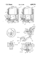
- FIG. 1 is a front elevational view with parts in section of a can filler unit of the prior art
- FIG. 2 is a front elevational view with parts in section of the preferred embodiment of this invention.
- FIG. 3 is a partial side elevational view taken from the left side of FIG. 2;
- FIG. 4 is an exploded perspective view of the adjusting means of this invention.
- FIG. 5 is a front elevational view of FIG. 4.
- FIG. 6 is a cross-sectional view taken on the line 6--6 of FIG. 3.
- FIG. 1 there is illustrated the lower part of a can filler unit 2 of a conventional can filling system such.
- the can filler unit 2 has a housing 4 in which the apparatus for filling a can with a liquid is located.
- a tulip 6 is slidably mounted on the housing 4 and sealing means 8 are provided between the housing 4 and the tulip 6.
- the housing 4 has a longitudinal axis 10 which coincides with the longitudinal axis of the can to be filled.
- a sealing member 12 is located in a cavity in the tulip 6 and is adapted to be moved into contact with the top of a can during the filling operation.
- a stirrup 14 has support means 16 on one end portion 18 thereof for holding a liquid level controller 20, such as a vent tube, for controlling the amount of the liquid being dispensed by the can filling operation so as to control the liquid level in a can.
- the other end portion 22 is mounted on the inner surface 24 by a threaded bolt 26 passing through an opening 28 and secured on the sidewall 30 by a nut 32 in threaded engagement with the threaded bolt 26.
- the lower part of the can filler unit 40 illustrated in FIG. 2 has many parts that correspond to FIG. 1 and have been identified with the same reference numerals.
- the mounting means for movably supporting the liquid level controller 20 is illustrated specifically in FIGS. 4-6 and comprises a generally L-shaped elongated member 42 having support means 44 at one end portion 46 thereof comprising an open ended U-shaped slot 48.
- the liquid level controller 20 is mounted on the support means 44 so that it extends upwardly into the housing 4.
- the other end portion 50 of the L-shaped elongated member 42 comprises a support arm 52 having a pair of spaced apart sidewalls 54 which have generally planar linearly extending surfaces in parallel relationship.
- the control means include a linearly extending slot 56 is formed in the support arm 52 and a pin 58 projects outwardly from the surface 60 for purposes described below.
- a groove 64 having linearly extending sidewalls 66 is formed in the inner surface 24 of the tulip 6 and is adapted to receive the sidewalls 54 for permitting sliding movement of the support arm 52 therein.
- the control means further include a shaft 70 having a generally cylindrical outer surface 72 passes through an opening 74 in the sidewall 30 of the tulip 6 and the opening 74 has a generally cylindrical inner surface which is slightly larger in diameter than the diameter of the generally cylindrical portion of the outer surface 72 so that the shaft 70 may be rotated therein.
- An integral enlarged head portion 76 is formed on one end portion of the shaft 70 and has a generally cylindrical outer surface 78 and has an open ended radially extending slot 80 formed therein for purposes described below.
- the other end portion of the shaft 70 comprises a threaded portion 82 which projects outwardly from the sidewall 30.
- a seal 84 seated in a recess in the sidewall 30 and a washer 86 are mounted on the shaft 70 to permit relative rotational movement therebetween.
- the threaded portion 82 has opposite flat sections 88 so that an indicating plate 90 having an opening 92 having a cross-sectional configuration similar to the cross-sectional configuration of the threaded portion 82 including opposite flat portions may be mounted thereon for rotation therewith to provide rotation prevention means for preventing relative rotation between the indicating plate 92 and the other end of the shaft.
- the indicating plate 90 has indicia 94 for cooperating with a mark 96 on the sidewall 30 to indicate the position of the liquid level controller 20.
- a nut 98 is threaded on to the threaded portion 82 to provide frictional forces between the support arm 52 and the groove 64 to hold the support arm 52 at a desired adjusted position in the groove 64.
- the support arm 52 is placed in the groove 64 and the threaded portion 82 of the shaft 52 is passed through the slot 56 into the opening 74.
- the movement of the shaft 70 is continued until the enlarged head portion 76 contacts the surface 60 and the pin 58 is located in the slot 80.
- the seal 84, the washer 86, the indicating plate 90 and the nut 98 are placed on the threaded portion 82 and the nut 98 is tightened so that the support arm 52 is in engagement with the groove 64.
- the indicating plate 90 and the shaft 70 are held against rotation so that the indicating plate 90 is in proper position relative to the mark 96.
- the flat sections 88, the slot 80 and the pin 58 are located relative to each other so that when the indicating plate 90 is on the threaded portion 82 and the zero indicia is opposite the mark 96, the liquid level controller 20 will be located at the position at which it is designed to operate.
- the nut 98 is loosened and the indicating plate 90 is rotated in the plus or minus direction and the nut 98 is tightened to hold the shaft 70 in the adjusted position. Therefore, the indicating plate 90 provides operating means so that rotation thereof rotates the shaft 70 to cause sliding movement of the support arm 52 and the control means.
- the rotation of the shaft 70 rotates the enlarged head portion 76 so that the walls defining the radial slot 80 bear against the pin 58 to move the support arm 52 in a linear direction in the groove 64.
- the linear direction of movement of the support arm 52 is parallel to the longitudinal axis 10.
Priority Applications (6)
| Application Number | Priority Date | Filing Date | Title |
|---|---|---|---|
| US07/305,072 US4899791A (en) | 1989-02-02 | 1989-02-02 | Liquid level control apparatus |
| CA002007967A CA2007967C (en) | 1989-02-02 | 1990-01-17 | Liquid level control apparatus |
| JP2504010A JPH04506328A (ja) | 1989-02-02 | 1990-01-30 | 液面調節装置 |
| BR909007075A BR9007075A (pt) | 1989-02-02 | 1990-01-30 | Aperfeicoamento em uma operacao de enchimento de lata |
| PCT/US1990/000511 WO1990008727A1 (en) | 1989-02-02 | 1990-01-30 | Liquid level control apparatus |
| EP19900904052 EP0455746A4 (en) | 1989-02-02 | 1990-01-30 | Liquid level control apparatus |
Applications Claiming Priority (1)
| Application Number | Priority Date | Filing Date | Title |
|---|---|---|---|
| US07/305,072 US4899791A (en) | 1989-02-02 | 1989-02-02 | Liquid level control apparatus |
Publications (1)
| Publication Number | Publication Date |
|---|---|
| US4899791A true US4899791A (en) | 1990-02-13 |
Family
ID=23179207
Family Applications (1)
| Application Number | Title | Priority Date | Filing Date |
|---|---|---|---|
| US07/305,072 Expired - Fee Related US4899791A (en) | 1989-02-02 | 1989-02-02 | Liquid level control apparatus |
Country Status (6)
| Country | Link |
|---|---|
| US (1) | US4899791A (ja) |
| EP (1) | EP0455746A4 (ja) |
| JP (1) | JPH04506328A (ja) |
| BR (1) | BR9007075A (ja) |
| CA (1) | CA2007967C (ja) |
| WO (1) | WO1990008727A1 (ja) |
Cited By (1)
| Publication number | Priority date | Publication date | Assignee | Title |
|---|---|---|---|---|
| US5969605A (en) * | 1998-04-30 | 1999-10-19 | Labatt Brewing Company Limited | Crimped can caliper |
Citations (7)
| Publication number | Priority date | Publication date | Assignee | Title |
|---|---|---|---|---|
| US2463922A (en) * | 1946-02-15 | 1949-03-08 | William E Turner | Liquid dispenser with receptacle operated outlet valve |
| US2761607A (en) * | 1954-02-15 | 1956-09-04 | American Machinery Corp | Filler-valve for filling containers |
| US2897855A (en) * | 1955-12-28 | 1959-08-04 | Fmc Corp | Container filling valve |
| US3420281A (en) * | 1966-07-07 | 1969-01-07 | Joseph S Tidwell | Liquid height determining device |
| DE2123866A1 (de) * | 1971-05-10 | 1972-11-30 | Holstein & Kappert Maschinenfabrik Phönix GmbH, 4600 Dortmund | Füllelement |
| US4614214A (en) * | 1985-03-21 | 1986-09-30 | Ruaro S.P.A. | Telescopic tap for the tanks of automatic liquid-filling machines |
| US4798234A (en) * | 1986-07-03 | 1989-01-17 | Adolph Coors Company | Can filling system |
Family Cites Families (2)
| Publication number | Priority date | Publication date | Assignee | Title |
|---|---|---|---|---|
| US3067785A (en) * | 1959-09-23 | 1962-12-11 | Meyer Geo J Mfg Co | Can filling head |
| US3908717A (en) * | 1970-08-29 | 1975-09-30 | Holstein & Kappert Maschf | Apparatus for filling beer cans or the like |
-
1989
- 1989-02-02 US US07/305,072 patent/US4899791A/en not_active Expired - Fee Related
-
1990
- 1990-01-17 CA CA002007967A patent/CA2007967C/en not_active Expired - Fee Related
- 1990-01-30 WO PCT/US1990/000511 patent/WO1990008727A1/en not_active Application Discontinuation
- 1990-01-30 BR BR909007075A patent/BR9007075A/pt unknown
- 1990-01-30 JP JP2504010A patent/JPH04506328A/ja active Pending
- 1990-01-30 EP EP19900904052 patent/EP0455746A4/en not_active Withdrawn
Patent Citations (7)
| Publication number | Priority date | Publication date | Assignee | Title |
|---|---|---|---|---|
| US2463922A (en) * | 1946-02-15 | 1949-03-08 | William E Turner | Liquid dispenser with receptacle operated outlet valve |
| US2761607A (en) * | 1954-02-15 | 1956-09-04 | American Machinery Corp | Filler-valve for filling containers |
| US2897855A (en) * | 1955-12-28 | 1959-08-04 | Fmc Corp | Container filling valve |
| US3420281A (en) * | 1966-07-07 | 1969-01-07 | Joseph S Tidwell | Liquid height determining device |
| DE2123866A1 (de) * | 1971-05-10 | 1972-11-30 | Holstein & Kappert Maschinenfabrik Phönix GmbH, 4600 Dortmund | Füllelement |
| US4614214A (en) * | 1985-03-21 | 1986-09-30 | Ruaro S.P.A. | Telescopic tap for the tanks of automatic liquid-filling machines |
| US4798234A (en) * | 1986-07-03 | 1989-01-17 | Adolph Coors Company | Can filling system |
Cited By (1)
| Publication number | Priority date | Publication date | Assignee | Title |
|---|---|---|---|---|
| US5969605A (en) * | 1998-04-30 | 1999-10-19 | Labatt Brewing Company Limited | Crimped can caliper |
Also Published As
| Publication number | Publication date |
|---|---|
| EP0455746A4 (en) | 1992-05-13 |
| BR9007075A (pt) | 1991-10-01 |
| CA2007967C (en) | 1994-06-14 |
| JPH04506328A (ja) | 1992-11-05 |
| WO1990008727A1 (en) | 1990-08-09 |
| CA2007967A1 (en) | 1990-08-02 |
| EP0455746A1 (en) | 1991-11-13 |
Similar Documents
| Publication | Publication Date | Title |
|---|---|---|
| US4588001A (en) | Rotary filling apparatus and method | |
| US7251921B2 (en) | Capping unit for closing containers with respective caps | |
| EP0629569B1 (en) | Star conveyor with adjustement device for variously-shaped containers | |
| US4679330A (en) | Concentricity gauge | |
| US3648741A (en) | Method and apparatus for accurately dispensing viscous products into successive containers | |
| US4514953A (en) | Device for removing air from filled bottles or other containers | |
| US5398485A (en) | Bottle support mechanism for a capping machine | |
| US4532968A (en) | Rotary filling apparatus and method | |
| US5816029A (en) | Anti-rotation device for capping machine | |
| EP2170757B1 (en) | A capping machine | |
| US4899791A (en) | Liquid level control apparatus | |
| US4653551A (en) | Adjustment devices for a machine for filling bottles and the like | |
| US5465496A (en) | Measuring apparatus and method | |
| US20030136465A1 (en) | Conveying unit for containers in filling machines | |
| EP1182165A1 (en) | Capping head with linear motor actuator | |
| GB2154992A (en) | Filling head | |
| IE50124B1 (en) | Filling of containers | |
| US5528879A (en) | Apparatus for applying closures to containers | |
| US4798234A (en) | Can filling system | |
| US2630204A (en) | Bottle spotting device | |
| US4102366A (en) | Drive mechanism for container filling machine | |
| US4773289A (en) | Torque wrench device | |
| US7127870B2 (en) | Replacement lock lever for an automatic beverage filling machine | |
| US6508498B1 (en) | Holding device for holding a container and a method for fixing a container | |
| JPH0462930B2 (ja) |
Legal Events
| Date | Code | Title | Description |
|---|---|---|---|
| AS | Assignment |
Owner name: ADOLPH COORS COMPANY, COLORADO Free format text: ASSIGNMENT OF ASSIGNORS INTEREST.;ASSIGNOR:TOTTEN, ROGER W.;REEL/FRAME:005026/0193 Effective date: 19890124 |
|
| AS | Assignment |
Owner name: COORS BREWING COMPANY, GOLDEN, CO 80401 A CORP. OF Free format text: ASSIGNMENT OF ASSIGNORS INTEREST.;ASSIGNOR:ADOLPH COORS COMPANY, A CORP. OF CO;REEL/FRAME:005610/0099 Effective date: 19901231 |
|
| FPAY | Fee payment |
Year of fee payment: 4 |
|
| REMI | Maintenance fee reminder mailed | ||
| LAPS | Lapse for failure to pay maintenance fees | ||
| FP | Expired due to failure to pay maintenance fee |
Effective date: 19980218 |
|
| STCH | Information on status: patent discontinuation |
Free format text: PATENT EXPIRED DUE TO NONPAYMENT OF MAINTENANCE FEES UNDER 37 CFR 1.362 |