US4899767A - Method and system for fluid treatment of semiconductor wafers - Google Patents
Method and system for fluid treatment of semiconductor wafers Download PDFInfo
- Publication number
- US4899767A US4899767A US07/283,465 US28346588A US4899767A US 4899767 A US4899767 A US 4899767A US 28346588 A US28346588 A US 28346588A US 4899767 A US4899767 A US 4899767A
- Authority
- US
- United States
- Prior art keywords
- fluid
- treatment
- tank
- vessel
- valve
- Prior art date
- Legal status (The legal status is an assumption and is not a legal conclusion. Google has not performed a legal analysis and makes no representation as to the accuracy of the status listed.)
- Expired - Lifetime
Links
Images
Classifications
-
- B—PERFORMING OPERATIONS; TRANSPORTING
- B05—SPRAYING OR ATOMISING IN GENERAL; APPLYING FLUENT MATERIALS TO SURFACES, IN GENERAL
- B05C—APPARATUS FOR APPLYING FLUENT MATERIALS TO SURFACES, IN GENERAL
- B05C3/00—Apparatus in which the work is brought into contact with a bulk quantity of liquid or other fluent material
- B05C3/02—Apparatus in which the work is brought into contact with a bulk quantity of liquid or other fluent material the work being immersed in the liquid or other fluent material
- B05C3/09—Apparatus in which the work is brought into contact with a bulk quantity of liquid or other fluent material the work being immersed in the liquid or other fluent material for treating separate articles
- B05C3/109—Passing liquids or other fluent materials into or through chambers containing stationary articles
-
- B—PERFORMING OPERATIONS; TRANSPORTING
- B08—CLEANING
- B08B—CLEANING IN GENERAL; PREVENTION OF FOULING IN GENERAL
- B08B3/00—Cleaning by methods involving the use or presence of liquid or steam
- B08B3/04—Cleaning involving contact with liquid
-
- B—PERFORMING OPERATIONS; TRANSPORTING
- B08—CLEANING
- B08B—CLEANING IN GENERAL; PREVENTION OF FOULING IN GENERAL
- B08B7/00—Cleaning by methods not provided for in a single other subclass or a single group in this subclass
- B08B7/0064—Cleaning by methods not provided for in a single other subclass or a single group in this subclass by temperature changes
- B08B7/0092—Cleaning by methods not provided for in a single other subclass or a single group in this subclass by temperature changes by cooling
-
- H—ELECTRICITY
- H01—ELECTRIC ELEMENTS
- H01L—SEMICONDUCTOR DEVICES NOT COVERED BY CLASS H10
- H01L21/00—Processes or apparatus adapted for the manufacture or treatment of semiconductor or solid state devices or of parts thereof
- H01L21/67—Apparatus specially adapted for handling semiconductor or electric solid state devices during manufacture or treatment thereof; Apparatus specially adapted for handling wafers during manufacture or treatment of semiconductor or electric solid state devices or components ; Apparatus not specifically provided for elsewhere
- H01L21/67005—Apparatus not specifically provided for elsewhere
- H01L21/67011—Apparatus for manufacture or treatment
- H01L21/67017—Apparatus for fluid treatment
- H01L21/67028—Apparatus for fluid treatment for cleaning followed by drying, rinsing, stripping, blasting or the like
-
- B—PERFORMING OPERATIONS; TRANSPORTING
- B08—CLEANING
- B08B—CLEANING IN GENERAL; PREVENTION OF FOULING IN GENERAL
- B08B2203/00—Details of cleaning machines or methods involving the use or presence of liquid or steam
- B08B2203/002—Details of cleaning machines or methods involving the use or presence of liquid or steam the liquid being a degassed liquid
-
- Y—GENERAL TAGGING OF NEW TECHNOLOGICAL DEVELOPMENTS; GENERAL TAGGING OF CROSS-SECTIONAL TECHNOLOGIES SPANNING OVER SEVERAL SECTIONS OF THE IPC; TECHNICAL SUBJECTS COVERED BY FORMER USPC CROSS-REFERENCE ART COLLECTIONS [XRACs] AND DIGESTS
- Y10—TECHNICAL SUBJECTS COVERED BY FORMER USPC
- Y10S—TECHNICAL SUBJECTS COVERED BY FORMER USPC CROSS-REFERENCE ART COLLECTIONS [XRACs] AND DIGESTS
- Y10S134/00—Cleaning and liquid contact with solids
- Y10S134/902—Semiconductor wafer
Definitions
- This invention relates to the manufacture of semiconductor components, and specifically to wet treatment of semiconductor wafers prior to or as part of certain fabrication steps.
- the invention relates to methods and systems for the cleaning of semiconductor wafers prior to diffusion, ion implantation, epitaxial growth, or chemical deposition steps, and also relates to methods for the wet processing of wafers, such as etching by treatment with fluids.
- process steps require contacting the wafers with fluids.
- process steps include etching, photoresist stripping, and prediffusion cleaning.
- chemicals utilized in these steps are quite dangerous in that they may comprise strong acids, alkalis, or volatile solvents.
- the equipment conventionally used for contacting semiconductor wafers consists of a series of tanks or sinks into which racks of semiconductor wafers are dipped.
- Wafer carriers are described, for example, in U.S. Pat. Nos. 3,607,478, 3,964,957 and 3,977,926.
- Such conventional wet processing apparatus poses several difficulties.
- a device known as a spin-rinser-drier is often used to dry wafers without water evaporation. These machines utilize centrifugal force to "throw" the water off the wafer surfaces. Problems can arise with wafer breakage because of the mechanical strain placed on the wafers, particularly with larger wafer sizes. Manufacturers are also challenged to minimize particulate generation in these usually somewhat complicated mechanical devices. Notwithstanding these drawbacks, some manufacturers have extended the spin-rinser-drier technology to general fluid processing.
- Spray methods also introduce new process difficulties. Because only a small amount of reagent is utilized, it is nearly impossible to achieve high temperature processing. In prediffusion cleaning, for example, it is desirable to expose the wafers to concentrated sulfuric acid at a temperature between 80 and 150 degrees Centigrade. Because the heat capacity of the sprayed solution is not very great, especially relative to the wafers themselves, it is nearly impossible to achieve the desired temperature on the wafer surface. The uniformity and control of temperature in acid processors is questionable. Similarly, it is difficult to achieve uniformity and control of processes such as hydrofluoric acid etching in which a relatively fast chemical reaction is taking place.
- What is needed in the area of semiconductor wet processing is an apparatus and process which can bring process chemicals into contact with semiconductor wafers in such a manner that: (a) atmospheric contamination is avoided, (b) personnel exposure to the chemicals is minimized, (c) uniform treatment of the wafer is promoted, (d) fast and effective heat transfer is allowed (e) stagnant conditions are minimized and "filming" effects are avoided, (f) the machine is mechanically simple, and (g) aggressive chemicals are handled safely.
- a treatment vessel for holding a plurality of semiconductor wafers, attached in a closed fluid loop.
- a fluid delivery system provides treatment fluid to the loop to hydraulically fill it.
- a circulation pump or other fluid mover then cause the fluid to circulate in a controlled manner for treating the wafers.
- the system for the fluid treatment of semiconductor wafers includes a treatment vessel having opposed first and second ports, and means for holding wafers in a flow path therebetween.
- a flow segment extends between the first and the second port so as to constitute, together with the vessel, a closed fluid loop.
- the flow segment comprises, in sequence, a first vent, a first valve, an inlet, a second valve and a second vent, so that by providing a fluid under pressure at the inlet, and selectively opening a valve and a vent, the vessel can be filled or drained through either the first or second port.
- the vessel and the flow segment are each designed to have no recesses, corners, or dead spaces which might retain fluid therein, so that the loop may be sequentially filled with various treatment fluids without leaving residues to cross-contamiminate the successive fluids.
- the loop is maintained hydraulically full, and as the vessel is filled with a treatment fluid from the inlet, a preceding treatment fluid is thereby flushed from the system.
- the first and second ports are top and bottom ports, with a flow path extending vertically therebetween.
- a sequence of treatment fluids of differing densities are provided at the inlet, and a vent and a valve are controlled to fill the loop from the bottom, in the event the treatment fluid is denser than the preceding fluid, or from the top, in the event the fluid is lighter than the preceding fluid.
- the loop includes a circulation pump or other means for recirculating fluid within the loop.
- the invention in another aspect, includes a fluid delivery system for the delivery of a sequence of high purity treatment fluids to a treatment vessel.
- the delivery system includes a measuring tank having opposed ports and configured for plug flow between the ports, and a metering pump having its inlet connected to one of the ports for withdrawing metered amounts of fluid from the tank.
- a plurality of reservoirs of treatment fluid are each connected via a respective associated valve to one of the ports.
- the tank is maintained hydraulically full, so that by opening a valve associated with a selected treatment fluid and actuating the pump to withdraw a metered volume of fluid from the tank, the metered volume of the selected treatment fluid is drawn into the tank.
- Passive or non-mechanical means is provided for delivering the contents of the tank to a treatment vessel. In this manner, the treatment fluids supplied to the treatment vessel are accurately metered, without having been in contact with possible sources of contamination, such as pump seals or moving mechanical parts.
- the means for delivering the contents of the tank includes gas pressure means for expelling the fluid in the tank through a port at the bottom of the tank.
- the opposed tank ports are top and bottom ports, and the treatment fluids are fluids of differing densities, with each fluid of lesser density connected via its associated valve to the top port, and each fluid of greater density connected via its associated valve to the bottom port. In this manner convective mixing during metered filling is minimized.
- a mixing tank is provided, between the measuring tank and the treatment vessel, for receiving metered amounts of fluid from the metering tank and homogeneously mixing the fluid before delivery to the treatment vessel. Such mixing may be accomplished by bubbling a gas through the fluid held in the mixing tank.
- the treatment fluid is a cleaning fluid, and a reactive gas, such as ozone, is bubbled through the fluid to enhance its cleaning power.
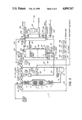
- FIG. 1 is a schematic drawing of a treatment vessel and flow loop according to the invention
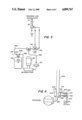
- FIG. 2 is a schematic view of a fluid delivery system according to the present invention.
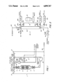
- FIG. 3 is a schematic view of a system for the treatment of semiconductor wafers according to the present invention.
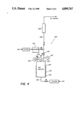
- FIGS. 4 and 5 each show fluid systems for use in the preferred embodiment of the invention described herein;
- FIG. 6 shows a section of a tank port with schematic valve of a preferred embodiment.
- the system of the invention shown in FIG. 3 is adapted to carry out the treatment of semiconductor wafers with a plurality of fluids, and includes a fluid loop for receiving and circulating a fluid past the wafers, and a fluid delivery system for supplying successive treatment fluids to the wafers.
- the primary constraint of wafer processing is that treatment fluids of exceptionally high purity must be used, and this purity must be maintained throughout the treatment. Because of the expense of the high quality fluids required, it is desirable to use relatively small amounts of fluid. This goal is largely inconsistent with the necessity for effectively removing each preceding process fluid and all contaminants from the wafers.
- FIG. 1 shows a simple schematic diagram of this portion of the system, which will be more readily understood by detailed reference thereto.
- the system of FIG. 3 includes a fluid delivery system in which a plurality of different treatment fluids may be mixed and delivered to the loop without contaminating or being contaminated by any mechanical parts other than the necessary valves and conduits, while efficiently conserving such fluids.
- FIG. 2 shows a simplified schematic diagram of this portion of the system of FIG. 3. Accordingly, FIGS. 1 and 2 will be discussed before the detailed discussion of the preferred wafer treatment system, FIG. 3.
- FIG. 1 shows a schematic diagram of the fluid treatment loop 1 of the present invention, in which a vessel 2 containing one or more semiconductor wafer carriers 3 is connected in a fluid system for treating the wafers with fluid.
- a suitable vessel 2 is disclosed in each of the above referenced patent applications, and comprises first and second fluid ports 4, 6, and means 3 for supporting semiconductor wafers in a flow path between the ports.
- a conduit 8 interconnects the ports 4,6 so as to form, together with the flow vessel 2, a loop in which fluid may circulate. Fluid is introduced via inlet 10 located in the conduit 8 between its ends.
- the conduit 8 includes, in series, a first vent 12, a first blocking valve 14, an inlet 10, a second blocking valve 16, and a second vent 18.
- inlet 10 comprises an instrument tee having smooth blunt ends for preventing entrapment of fluids therein, and preferably the distance from tee 10 to valves 14, 16 is minimized so as to eliminate dead legs in the conduit system during the filling operation.
- Each vent 12, 18 preferably communicates to the drain over a slight vertical rise, shown schematically at 13, to minimize backflow problems. All components are lined with inert material, and preferably with material which is impermeable and non-adsorbent for the fluids used.
- the loop 2, 8, 10,12, 14, 16, 18, also includes a pump 20 for circulating fluid in the loop.
- Pump 20 is a variable speed pump, controllably operated at between 60 and 3,000 RPM, with a peak capacity in the range of 200 liters per minute.
- a valve (not shown) controlling the fluid supply to inlet 10 is closed and both valves 14, 16 are opened, permitting circulatory flow in the loop.
- Pump 20 is turned on at a slow speed, and its speed increased to circulate the fluid through vessel 2 for treatment of the wafers therein.
- the volumetric capacity of vessel 2 is approximately 3 liters, with the conduit 8 comprising another 3 liters or 50% of the total treatment volume.
- Vessel 2 includes flow expansion and flow extraction portions (which terms are relative to the direction of the flow) which may comprise helical spinners 5 for imparting plug flow to fluid entering or leaving the vessel. Suitable mechanisms are those described, for instance, in the above referenced applications, Ser. Nos. 612,355 and 747,894.
- vents 12, 18 are spring-loaded, normally-open vents, so that, if the failure of the control system for the various valves and vents should occur, treatment fluids will flush harmlessly out of the vents to the drain, and no excessive pressure buildup will occur.
- vents 12,18 are air-actuated valves, and are "tied” together, so that closing of one vent automatically opens the other.
- Pump 20 is a centrifugal pump which allows fluid to freely flow past it when the pump is turned off, as, for instance, during the filling of the loop.
- valves 14-16 92 may all be replaced by one three-port, three-position valve which may be positioned to interconnect any pair of its ports.
- valve 12 to the drain and blocking valve 14 may be replaced by a suitable three port two-position valve, with the common port connected to inlet 10.
- FIG. 2 there is shown a simplified schematic diagram of a fluid delivery system 30 for measuring high purity fluids and delivering such fluid to the inlet 10 of the fluid loop, according to the present invention, in a semiconductor wafer treatment system.
- Delivery system 30 includes a measuring tank 32 and a plurality of sources of treatment fluids F1, F2, F3, each connected to the mixing tank 32 by a respective valve 34a, 34b, 34c.
- Tank 32 has a port 36 at its top and a port 38 at its bottom, with the respective valves 34a, 34b, 34c each connected to one of the ports, as explained more fully below.
- a first valve 40a is connected to port 36 and a second valve 40b is connected to port 38 with the other side of each valve connected to a common manifold 42 leading to an input of a metering pump 44.
- the output of pump 44 connects to a drain.
- a source of pressurized gas shown illustratively as N2
- Conduit 50 communicating with the drain, connects to top port 36 via valve 52.
- conduit 60 connects to bottom port 38 via valve 62 for carrying metered fluids from the tank, and solvent, rinse or make-up fluids to the tank.
- line 50 is a drain and line 60 is the fluid output of the system.
- Fluid delivery system 30 is used to measure fluids for delivery to a treatment vessel as follows.
- Tank 32 is maintained in a hydraulically full condition with all valves 34a, 34b, 34c, 40a, 40b, 46, 52, 62 closed.
- the term "hydraulically full" means full of liquid, without gas pockets or phase boundaries.
- the hydraulic filling may be accomplished, for instance, by initially opening valve 52 to the drain and valve 62 to a water source so as to fill the tank with water up to the level of the drain, and then closing said valves.
- Tank 32 is long and thin; in one prototype embodiment it has dimensions of 2 inches diameter by 52 inches length. It will be understood, however, that the volume of tank 32 may be selected according to the fill volume of a representative cycle of the treatment system designed, or according to the volume of fluids to be metered into such a system.
- the valve corresponding to the desired treatment fluid is opened so as to connect that treatment fluid to a port 36 or 38 of tank 32.
- the valve (40a or 40b) which connects the metering pump 44 to the opposing port of tank 32 is also opened.
- Pump 44 is then turned on to withdraw the metered amount of fluid from the hydraulically full tank 32, thereby causing fluid from the reservoir of selected fluid to enter the tank.
- the valve 34b is opened to connect that fluid to port 38
- the valve 40a is opened to connect the metering pump 44, via the manifold 42, to the opposing port 36.
- tank 32 is configured for plug flow, so that entering fluid substantially uniformly displaces the fluid ahead of it in its flow direction. With this geometry, a substantial proportion, e.g., over 50%, of tank 32 may be filled with a fluid in this manner without loss of accuracy.
- port 36 is a top port and port 38 a bottom port, with lighter fluid F1 connected to the top port and denser fluids, F2, F3 connected to the bottom port.
- F1, F2, F3, and the H 2 O are high purity fluids for the treatment of semiconductor wafers. Because each fluid is drawn into the tank without actually contacting the pump, the mixed fluids in the tank are of a purity equal to those initially supplied to it. Thus, the metering step introduces no contamination to the fluids.
- valve 34b and valve 40a are again closed and valve 62, connecting the bottom port 38 to the outlet conduit 60, is opened.
- Valve 46 is also opened, causing a pressurized non-reactive gas to bear against the top of the fluid in the tank, driving the fluid in the tank out through the conduit 60.
- the pressurized transport gas is also of high purity.
- conduit 60 is connected to a second tank, as in the embodiment of FIG. 3, discussed below.
- the second tank serves as an accumulating and mixing vessel, in which phase separation may occur, thus permitting delivery of bubble-free fluid to the wafer cleaning system.
- valve 46 is closed and valves 52 and 62 opened, allowing water to flow into port 38, through the tank 32 to port 36, through conduit 50 to the drain.
- metering pump 44 is turned on, and valves 40a and 40b each alternately opened and closed, so as to draw rinse water through the manifold 42 and each leg of its connecting pipes and valves. This rinses the metering system 30 and measuring tank 32 and re-establishes the hydraulically full condition, so that the tank is again ready for metering of fluids and delivery thereof to the treatment system.
- pump 44 withdraws substantially pure water, and thus becomes minimally contaminated between pumping cycles. More importantly, the fluid which does contact pump 44 does so directly en route to a drain, so that the pump introduces no contaminants such as lubricants or particulate matter into the system. Further, residual treatment fluid in tank 32, which might be detrimental to subsequent processing steps, is purged from tank 32 before each metering cycle.
- FIG. 2 shows three treatment fluids F1, F2, F3, a significantly larger number of fluids may be connected by respective valves to the ports of the tank for measuring thereof. Furthermore, two or more such fluids may be measured in a single cycle before delivery through line 60 to an accumulating tank or to the treatment system.
- the fluid delivery system 30 offers a high degree of versatility for measuring and delivering a complex sequence of fluids using evacuative flow measuring and purging, while introducing none of the contaminants commonly associated with fluid metering and transport systems.
- FIG. 3 shows a schematic view of a wafer treatment system according to the present invention, with additional structures which permit the ready interchange or adaptability of the system to diverse fluid treatment reagents and protocols.
- the operation of the system will be described below with reference to a number of particular treatment fluids useful in cleaning semiconductor wafers. It will be appreciated, however, that the invention includes a system and method not only for high purity cleaning and rinsing operations, but also for other wafer processing operations. Such processing operations may include "wet", e.g., liquid, treatment, or the flow treatment with gas or vapor fluids.
- a preferred system comprises a flow loop portion 1 and a fluid measuring portion 30, as previously described in reference to FIGS. 1 and 2, respectively.
- corresponding parts e.g. vessels, tanks, valves, conduits and pumps, are numbered identically to the numbering of FIGS. 1 and 2.
- treatment loop 1 includes a vessel 2, a first vent 12, a first valve 14, an inlet 10, a second valve 16 and a second vent 18 connected via conduit 8 in a loop running between top and bottom ports 4,6 of the vessel.
- fluid metering system 30 contains all the elements referred to by numerals in FIG. 2. It will be seen that the output conduit 60 of the metering system 30 is connected to inlet 10 of the loop.
- a chemical mixing tank 70 having a top port 72 and a bottom port 74.
- Mixing tank 70 is larger than measuring tank 32, and has a volume sufficient to fill the treatment loop 1.
- Mixing tank 70 unlike fluid vessel 2 and measuring tank 32, is not maintained hydraulically full, but may have a phase boundary 75 between the fluid therein and gas or vapor in the upper portion of the tank.
- a valve 76 connects fluid line 60 to the bottom port 74 of the mixing tank.
- Another valve 78 located downstream of valve 76 along line 60 may be closed so as to divert the flow of fluid in line 60 to the mixing tank.
- the top port 72 of the mixing tank is connected via valve 80 to a source of pressurized gas which may be used to propel fluid from the tank into the loop, in a manner similar to that discussed for the measuring tank in relation to FIG. 2. Also connected to port 72 is an outlet valve 82 leading to the drain.
- a level and temperature indicator 84 is attached at the top of tank 70, and heater elements 86, controlled in accordance with the temperature indication, surround tank 70 for heating the fluid in the tank to a selected temperature.
- a pressurized gas inlet valve 88 for introducing pressurized gas, bubbled through the fluid, to promote mixing.
- the pressurized gas is ozone which serves the dual functions of agitating the fluid, and providing a reactive species for inhibiting etching and for oxidizing organic contaminants from the wafers.
- a conductivity sensor 90 for monitoring the conductivity of the fluid admitted or discharged through port 74.
- a plug flow imparting element similar to 5 of FIG. 1 may be used at port 74.
- Conduit 60 running from the measuring tank 32 to the inlet 10 via valve 92, thus may be connected to the bottom port 74 of mixing tank 70 by selectively opening or closing valves 62, 76, 78.
- a main water inlet line 94 is also connected, via positioning valve 96, to line 60 at a point thereof near the inlet valve 92 to the vessel treatment loop.
- Inlet line 94 supplies a flow of high purity water, at a rate determined by the position of the positioning valve 96, to line 60.
- By closing valve 78, and opening valve 92 the high purity water flows directly into the fluid treatment loop 2,8,10,12,14, 16,18.
- valve 92 and opening valve 78 water flows along line 60 to either mixing tank 70 or measuring tank 32.
- conduit 60 serves the dual function of providing, in a first direction, a flow of treatment fluid from tanks 32, 70 to the treatment vessel 2, and providing, in a reverse direction, a flow of rinse water or makeup water for the tanks 32, 70.
- the conductivity sensor 90 at the inlet to tank 70 will provide a resistance reading indicative of the purity of the water flowing therethrough. Sensor 90 will also provide a high (infinite) resistance reading if the fluid in tank 70 passes entirely out of the tank.
- Such a condition may arise when, for instance, the pressurized gas at inlet valve 80, for driving the fluid in the mixing tank into the treatment loop, entirely empties tank 70. This is to be avoided because, as explained more fully in the prior referenced patent applications Ser. Nos. 612,355, 747,895 and 765,294, the fluid treatment loop is maintained in a hydraulically full condition, so as to avoid phase transitions in the treatment fluid and to provide more uniform and efficient wafer-fluid contact.
- vents 12, 18 are spring-loaded fail-open valves.
- hydrophilically full when used in reference to the treatment vessel or treatment loop, includes the term fluidically full, and means the vessel or loop is full of a liquid, or a gas or vapor, having no phase boundaries, so that the fluid may circulate in a uniform fashion, without droplets, films or other irregularities which could degrade the wafer treatment process.
- sensors 100, 102 are resistivity or conductivity sensors similar to sensor 90, except that one is a high range sensor and the other a low range sensor, for providing accurate indications of resisitivity or conductivity of fluid passing in the line.
- sensor 102 may be a sensor capable of accurate resistance readings in the range of 1 to 18 megohm-centimeters.
- Sensor 100 is a similar sensor covering a conductivity range 0 to 20,000 micromhos/centimeter.
- Drain 98 also has a flow indicator 106, which, alternatively, may be placed on the distilled water inlet line 94.
- flow indicator 106 For the flow indications of interest, with the system operated in a hydraulically full state, the measurement of flow in the drain will provide an accurate indication of the flow into the system along line 94, and for this reason the placement of flow indicator 106 on the drain is preferred.
- a liquid sensor 108 is provided along the common drain line 50 of tanks 32, 70 to provide an indication when one of those tanks has been entirely filled with fluid, as occurs during the backwash rinsing operation.
- a liquid sensor, in the conduit 8, a pressure indicator, and a temperature indicator may monitor the fluid in the treatment loop.
- the loop may be insulated, or heated by electric wrap tape, and temperature monitored only in tank 70 and/or drain 98.
- Filters 35a, 35b, 35c are provided between the sources of treatment fluids and the measuring tank, and a filter may also be provided along the inlet line 94.
- FIG. 4 shows an auxiliary fluid delivery system 120 according to a preferred embodiment of the invention for the practice of semiconductor wafer cleaning.
- Auxiliary fluid delivery system 120 delivers treatment fluid along the line 122 to the upper port 4 of vessel 2.
- system 120 delivers a fluid for drying the contents of vessel 2. This process step inherently cannot be performed with the vessel full of liquid. Nonetheless, it is desired to effect such drying without the formation of bubbles and without leaving droplets on the semiconductor wafers, since droplets, upon drying, leave contaminant residues of the solutes therein. In the preferred embodiment, this is accomplished by providing a flow of heated isopropyl alchohol (IPA).
- IPA heated isopropyl alchohol
- the auxiliary fluid delivery system 120 includes an alchohol boiler 124 having an inlet 126 and an outlet 128. Heaters 130 maintain the contents of the boiler at high temperature. A pressure indicator 132 provides information for controlling the heat range, and a temperature indicator 134 monitors the temperature of the fluid leaving outlet 128. A safety relief valve 136 is provided at the top of the boiler 124. A valve 138 controls access to delivery line 122. Also connected to line 122 is a source of high temperature gas, which may be, for instance, filtered nitrogen, which is passed through gas heater 137.
- the pressurized, vapor IPA is introduced into vessel 2, displacing the fluid therein. Any pressure and temperature drop causes a certain amount of IPA droplet condensation on the wafers and vessel walls, which forms an azeotrope with any remaining water. Continued flow of hot IPA vapor and heated drying medium, as previously described completes the drying step.
- IPA drying system it is also possible to operate the wafer treatment system of the present invention, using, for example, heated concentrated H 2 SO 4 as a treatment fluid.
- a strong acid treatment is commonly used in the semiconductor industry for the removal of gross organic contaminants.
- Details for the construction of a sulfuric acid cleaning system are disclosed in the above-referenced patent application, Ser. No. 765,294 incorporated herein by reference, and accordingly no further details need be given here.
- the fine-fluids metering system 140 includes a fluid source or reservoir 142 having inlet and outlet ports 144a, 144b, respectively. Conduit 146b extends from outlet 144b to an inlet of a metering pump 148. An outlet of the metering pump 148 goes to a filter 150, whence the filtered fluid moves by conduit 146c to valve 152. A further conduit 146a extends from the fluid reservoir inlet 144a to valve 152.
- Valve 152 is a three port, 2 position valve which, in its normal position, connects conduit 146c to conduit 146aso as to define a simple flow loop of the fluid reservoir via the metering pump and the filter back to the fluid reservoir. In its second position, valve 152 shunts the flow from 146c to valve 154.
- Valve 154 is also a three port, 2 position valve, with the other 2 ports connected to the inlet portion of valve 92 of FIG. 3, on opposing sides of an orifice plate which serves to create a pressure differential across the inlet to the valve, when fluid flows through the valve, thereby creating a scavenging flow in the loop connected to the opposing side of the orifice plate.
- valves 152, 154 are tied together, so that when valve 152 is in its first position shunting line 146a to line 146c, valve 154 connects the two injection flow ports at inlet to valve 92.
- a five port, four way valve may also be used in place of the two three port, 2 position valves.
- a recirculating flow loop 146a, 146b, 146c in the HF fluid delivery system allows metering pump 148 to operate at a constant speed, thereby enhancing its accuracy. Furthermore, by connecting the flow loop via valve 154 directly at the inlet to inlet valve 92, very exact timing of the HF injection to the treatment loop is obtained, and concentrations, e.g., of 0.5% may be routinely achieved with high accuracy.
- treatment fluids delivered by the fine-fluids system, FIG. 5, are not recirculated in the treatment loop 2, 8 but are flowed directly through vessel 2 to the drain.
- each of the valves controlling the inflow of a treatment fluid or a gas into the system is a self rinsing valve, like the three-port two-way valve 156 of FIG. 5, and is connected so that the valve is rinsed during the rinsing of the tank to which it leads.
- This is accomplished, in a preferred system, by placing the valve for each such fluid or gas directly at the inlet or outlet of a tank, and providing a flow geometry to create a pressure differential for inducing a rinse flow through the valve.
- FIG. 6 shows an axial cross section through a port 601 at a representative tank 600 having fluid inlet valve 700 so attached.
- Tank 600 may be, for instance, mixing tank 70 or measuring tank 32.
- Port 601 may be either a top or bottom port of tank 600.
- Port 601 comprises a wall portion 602 which is generally cylindrical, and which has an inlet 603 connected to a bulk fluid supply, such as to line 60 or a drain.
- An orifice plate 604 in port 601 constricts flow between tank 600 and inlet 603 so as to create a pressure differential between opposing sides of plate 604, with the high pressure on the upstream side.
- Wall portion 602 is drilled, and threaded inlets 605, 606 are tapped therein on opposing sides of plate 604, to accommodate a self rinsing valve 700.
- Valve 700 controls the access of a fluid F to the tank 600.
- Fluid F may be, for instance, the ozone mixing gas or the transport gas N 2 used in tank 70, 32, or may be a treatment fluid such as the fluids F1, F2, F3 discussed in relation to FIG. 2.
- Valve 700 has an inlet port 704 in communication with a supply of the fluid F, and further has ports 705, 706 directly connected to the tapped holes 605, 606 of tank 600.
- Valve 700 is a three-way, two-position valve, with port 705 connected in a first position to port 706 so as to provide a bypass flow about orifice plate 604 when fluid flows between tank 600 and inlet 603, thereby rinsing the valve.
- port 706 connects to port 704, allowing fluid F to enter tank 600 at 606.
- the cylindrical wall 602 of port 601 may be drilled and tapped with a plurality of pairs of inlets similar to 605, 606, spaced around its circumference, so as to accommodate additional inlet valves for a plurality of different fluids F1, F2 etc.
- the schematic configuration of valves, treatment fluids and other gases of FIGS. 1-5 employs a physical layout of inlet valves similar to the valve 700 attached to the tank ports as illustrated in FIG. 6.
- each of valves 80, 88, 46, 34a, 34b, 34c may be so attached.
- such a valve (not shown) may be attached to the top port of vessel 2 for each of the special fluids (isopopyl alcohol, sulfuric acid) discussed herein.
- a preferred method of using the invention involves an improvement of the "RCA" cleaning system for semiconductor wafers.
- concentrations of fluids, the treatment times, and in some cases the composition of such fluids are modified according to the practice of the present invention.
- Vessel 2 for use in a flow loop may, for instance, comprise modular stackable wafer carriers, as described in the earliest above-mentioned application, or may comprise a flow vessel having a door-like opening therein, for inserting standard wafer carriers. Vessel 2 is then sealed, and an optional pre-cleaning step is performed. Hot concentrated sulfuric acid cleaning fluid, preferably comprising 96% H 2 SO 4 at 300° F. is introduced into vessel 2, and then circulated through the vessel and flow loop for 5-20 minutes.
- the acid may contain hydrogen peroxide, in a manner known in the art, or preferably may have ozone sparged therethrough, so as to provide a medium capable of oxidizing organics.
- the H 2 SO 4 is displaced out of vessel 2 in a top down fashion by closing vent 12 and valve 16 and opening a gas inlet valve (not shown) similar to valves 46, 80, of FIG. 3, at port 4. This flushes the H 2 SO 4 downwardly through the bottom port 6 of vessel 2 whence the acid may be channelled by valves (not shown) to a recycling reservoir.
- a gas inlet valve (not shown) similar to valves 46, 80, of FIG. 3, at port 4.
- the gas is turned off, and a rinse commenced. From this point on, all processing steps until final drying are conducted with the vessel 2 and loop in a hydraulically full condition.
- vent 18 and valve 14 are closed, and valves 92, 96 opened to fill the vessel 2 with water from the bottom up.
- the vents and valves are then reversed to provide a downflow H 2 O, which is continued until the rinse water is clean, as detected, for example, by a resistance reading in the range of 10 megohmns or more measured by sensor 100 or 102 at the drain.
- Inlet valve 92 is then closed.
- the next treatment fluid is then metered in fluid delivery system 30 for the next processing step.
- the second treatment fluid is an oxidizing ammonium hydroxide fluid similar to the familiar SC-1 cleaning fluid, and having a 10% NH 4 OH solution with sufficient hydrogen peroxide added to inhibit etching of SiO 2 or Si 3 N 4 .
- This fluid is prepared in a manner previously described in relation to FIG. 2 above, by sequentially metering the desired quantities of treatment fluids through valves 34a, 34b into metering tank 32 and delivering them to the chemical mixing tank 70.
- the heater 86 is turned on and controlled to heat the solution to 85° C. After a suitable volume of fluid has accumulated in mixing tank 70 in the appropriate concentration, it is ready for delivery to the fluid treatment loop 1.
- an ozone generator may be provided and ozone bubbled into the mixing tank 70 via valve 88, as previously described in relation to FIG. 3.
- This manner of introduction of hydrogen peroxide employs a gas, which may be of greater purity than a liquid reagent, and enhances mixing in tank 70.
- the bubbling of the ozone in the mixing tank can provide an alternative or an additional source of H 2 O 2 to the treatment fluid.
- valve 62 (FIG. 3) is closed, valve 78 is opened, and gas pressure valve 80 at the top of the mixing tank is opened to provide pressurized gas for driving the fluid through conduit 60 to the inlet 10.
- vent 18 is opened, valve 16 and vent 12 are closed, and valve 14 is opened.
- valve 92 to the inlet 10 is opened so that the ammonium hydroxide cleaning fluid travels along conduit 60 into the flow loop at the top port 4 of vessel 2, driving the preceding treatment fluid (the water rinse) downwardly through vessel 2 and out vent 18 to the drain.
- the treatment vessel 2 and the flow loop are maintained hydraulically full so that no bubbles or phase boundaries are encountered.
- the bubbles which may have been introduced by the ozone bubbling in tank 70 are allowed to separate at the phase boundary 75 in the mixing tan 70 before entering the flow loop.
- the introduction of the ammonium hydroxide fluid at the top of vessel 2 causes displacement of water in the vessel downwardly without mixing. That is, the direction of the flow of the introduced fluid is against the flotation gradient of the introduced fluid with respect to the preceding fluid.
- the same principal will dictate the direction of introduction of each fluid into the loop, e.g., with lighter fluids introduced at the top of the vessel 2 and heavier fluids introduced at the bottom of vessel 2.
- the rinse water will be introduced in the direction of its flotation gradient with respect to the preceding fluid. That is, lighter fluids will be rinsed out by introducing water via the bottom port of vessel 2, and heavier fluids will be rinsed out by the introduction of water at the top part of vessel 2.
- valve 92 is closed, blocking valve 16 is opened, and the circulation pump 20 is turned on.
- the ammonium hydroxide solution then circulates for approximately 10 minutes, after which time it is rinsed out.
- the rinse is accomplished by closing valve 14 and vent 18, opening vent 12 and valves 16 and 92, so as to cause the introduction of water through bottom port 6 to fill vessel 2, rinsing it out through the drain 12.
- a brief treatment of extremely dilute hydrofluoric acid HF is used to remove surface oxide and better expose organic contaminants for cleaning.
- This step is accomplished by controlling the hydrofluoric acid valve as discussed above in relation to FIG. 5, so as to provide a dilute solution of between 0.1 and 5%, and preferably between 0.5 and 1% HF at the inlet valve 92 to the system. Vent 12 and valve 16 are opened, and vent 18 and valve 14 closed, so that when valve 92 is opened the dilute hydrofluoric solution is introduced into vessel 2 at the bottom port thereof.
- the controlled introduction of the correct concentration of HF is accomplished by switching the tied valves 152, 154 to connect the flow of HF from the fine metering pump 148 to the mixing inlet of valve 92, while simultaneously controlling the inlet water flow using positioning valve 96, as discussed above with regard to FIG. 5, so as to achieve the desired concentration and flow rate.
- the HF solution is purged from the vessel by simply halting the HF injection and continuing the water flow.
- the next treatment fluid is an HCl-based fluid similar to the familiar semiconductor cleaning fluid SC-2, and comprises a 10% solution of hydrochloric acid with added hydrogen peroxide.
- This solution is prepared in fluid delivery system 30 as described in regard to FIG. 2 above, so as to provide a sufficient volume of the HCl and H 2 O 2 solution in the mixing tank 70 to fill the fluid treatment loop 1.
- Heaters 86 around the mixing tank raise the temperature of the treatment fluid to 85° C., as discussed in relation to the ammonium hydroxide-based treatment fluid, and ozone may be bubbled through the mixing tank to promote mixing and to enhance its oxidizing abilities.
- Valve 62 is then closed and valves 76, 78 opened to permit fluid to flow along the conduit 60 to the inlet 10.
- valve 80 is opened, and pressurized gas drives the prepared HCl treatment fluid through conduit 60.
- valve 16 and vent 12 of the flow loop are opened, valve 14 and vent 18 are closed, and valve 92 at the inlet 10 opened to permit fluid from tank 70 to enter the flow loop.
- the fluid then enters the flow loop, filling vessel 2 through bottom port 6 and displacing the water rinse upwardly out of vent 12 to the drain.
- inlet valve 92 is closed, valve 14 opened, and the circulation pump 20 is turned on and brought up to speed to circulate the solution for 10 minutes.
- the HCl solution is then removed, by setting the vents and valves to provide a top-down introduction of a water rinse, in a manner similar to, (but with flow direction reversed from) that described for the SC-1 treatment fluid.
- valves 14, 16 and vent 12 are closed, vent 18 is opened, and a flow of heated drying medium is introduced through the vessel 2.
- the drying fluid is an azeotrope-forming vapor, such as isopropyl alcohol, as described with regard to FIG. 4, above.
- a conventional solvent-based rinse may be used, such as sustained hot methanol rinse followed by methanol vapor/hot gas purge.
- the various valves are all diaphragm valves, pneumatically controlled by a common 60 psi pressure source.
- the proper sequence and timing of the valves is controlled by a computer program run on a microprocessor to effect the desired mixing, heating, delivery and circulation of fluids, and drying as outlined above.
Abstract
Description
Claims (19)
Priority Applications (1)
| Application Number | Priority Date | Filing Date | Title |
|---|---|---|---|
| US07/283,465 US4899767A (en) | 1984-05-21 | 1988-12-12 | Method and system for fluid treatment of semiconductor wafers |
Applications Claiming Priority (4)
| Application Number | Priority Date | Filing Date | Title |
|---|---|---|---|
| US06/612,355 US4577650A (en) | 1984-05-21 | 1984-05-21 | Vessel and system for treating wafers with fluids |
| US06/747,894 US4633893A (en) | 1984-05-21 | 1985-06-24 | Apparatus for treating semiconductor wafers |
| US06/765,294 US4778532A (en) | 1985-06-24 | 1985-08-13 | Process and apparatus for treating wafers with process fluids |
| US07/283,465 US4899767A (en) | 1984-05-21 | 1988-12-12 | Method and system for fluid treatment of semiconductor wafers |
Related Parent Applications (1)
| Application Number | Title | Priority Date | Filing Date |
|---|---|---|---|
| US06/805,203 Division US4795497A (en) | 1985-08-13 | 1985-12-04 | Method and system for fluid treatment of semiconductor wafers |
Publications (1)
| Publication Number | Publication Date |
|---|---|
| US4899767A true US4899767A (en) | 1990-02-13 |
Family
ID=40800439
Family Applications (3)
| Application Number | Title | Priority Date | Filing Date |
|---|---|---|---|
| US07/184,544 Expired - Lifetime US4911761A (en) | 1984-05-21 | 1988-04-20 | Process and apparatus for drying surfaces |
| US07/252,823 Expired - Lifetime US4917123A (en) | 1984-05-21 | 1988-10-03 | Apparatus for treating wafers with process fluids |
| US07/283,465 Expired - Lifetime US4899767A (en) | 1984-05-21 | 1988-12-12 | Method and system for fluid treatment of semiconductor wafers |
Family Applications Before (2)
| Application Number | Title | Priority Date | Filing Date |
|---|---|---|---|
| US07/184,544 Expired - Lifetime US4911761A (en) | 1984-05-21 | 1988-04-20 | Process and apparatus for drying surfaces |
| US07/252,823 Expired - Lifetime US4917123A (en) | 1984-05-21 | 1988-10-03 | Apparatus for treating wafers with process fluids |
Country Status (1)
| Country | Link |
|---|---|
| US (3) | US4911761A (en) |
Cited By (80)
| Publication number | Priority date | Publication date | Assignee | Title |
|---|---|---|---|---|
| US4993271A (en) * | 1988-12-12 | 1991-02-19 | Micron Technology, Inc. | Liquid in situ multiport monitoring system |
| WO1992016306A2 (en) * | 1991-03-19 | 1992-10-01 | Startec Ventures, Inc. | Manufacture of high precision electronic components with ultra-high purity liquids |
| US5190065A (en) * | 1991-11-29 | 1993-03-02 | International Business Machines Corporation | Self-contained washing unit for printed circuit boards |
| WO1993006949A1 (en) * | 1991-10-04 | 1993-04-15 | Cfm Technologies, Inc. | Ultracleaning of involuted microparts |
| US5277715A (en) * | 1992-06-04 | 1994-01-11 | Micron Semiconductor, Inc. | Method of reducing particulate concentration in process fluids |
| US5286657A (en) * | 1990-10-16 | 1994-02-15 | Verteq, Inc. | Single wafer megasonic semiconductor wafer processing system |
| US5464480A (en) * | 1993-07-16 | 1995-11-07 | Legacy Systems, Inc. | Process and apparatus for the treatment of semiconductor wafers in a fluid |
| US5489557A (en) * | 1993-07-30 | 1996-02-06 | Semitool, Inc. | Methods for processing semiconductors to reduce surface particles |
| US5653045A (en) * | 1995-06-07 | 1997-08-05 | Ferrell; Gary W. | Method and apparatus for drying parts and microelectronic components using sonic created mist |
| US5656097A (en) * | 1993-10-20 | 1997-08-12 | Verteq, Inc. | Semiconductor wafer cleaning system |
| US5780363A (en) * | 1997-04-04 | 1998-07-14 | International Business Machines Coporation | Etching composition and use thereof |
| US5819770A (en) * | 1996-12-23 | 1998-10-13 | Randall Manufacturing Co. | Cleaning apparatus with solution flushing system for tubes and other articles |
| US5833760A (en) * | 1995-12-30 | 1998-11-10 | Samsung Electronics Co., Ltd. | Apparatus and method for cleaning semiconductor devices without leaving water droplets |
| US5842491A (en) * | 1995-12-18 | 1998-12-01 | Lg Semicon Co., Ltd. | Semiconductor wafer cleaning apparatus |
| US5845663A (en) * | 1996-03-13 | 1998-12-08 | Lg Semicon Co., Ltd. | Wafer wet processing device |
| US5911837A (en) * | 1993-07-16 | 1999-06-15 | Legacy Systems, Inc. | Process for treatment of semiconductor wafers in a fluid |
| US5937876A (en) * | 1998-11-03 | 1999-08-17 | United Microelectronics Corp. | Rinsing system used in a photoresist coater with capability to avoid a reversed pressure effect |
| US5948173A (en) * | 1996-04-12 | 1999-09-07 | Lg Semicon Co., Ltd. | System and method for cleaning a semiconductor wafer |
| US5950645A (en) * | 1993-10-20 | 1999-09-14 | Verteq, Inc. | Semiconductor wafer cleaning system |
| US5964958A (en) * | 1995-06-07 | 1999-10-12 | Gary W. Ferrell | Methods for drying and cleaning objects using aerosols |
| US5968285A (en) * | 1995-06-07 | 1999-10-19 | Gary W. Ferrell | Methods for drying and cleaning of objects using aerosols and inert gases |
| US5972123A (en) * | 1997-06-13 | 1999-10-26 | Cfmt, Inc. | Methods for treating semiconductor wafers |
| US6001223A (en) * | 1995-07-07 | 1999-12-14 | Air Liquide America Corporation | On-site ammonia purification for semiconductor manufacture |
| US6015477A (en) * | 1994-01-07 | 2000-01-18 | Air Liquide America Corporation | Point-of-use ammonia purification for electronic component manufacture |
| US6033996A (en) * | 1997-11-13 | 2000-03-07 | International Business Machines Corporation | Process for removing etching residues, etching mask and silicon nitride and/or silicon dioxide |
| US6049996A (en) * | 1998-07-10 | 2000-04-18 | Ball Semiconductor, Inc. | Device and fluid separator for processing spherical shaped devices |
| WO2000024687A1 (en) * | 1998-10-26 | 2000-05-04 | Yieldup International | Method and apparatus for cleaning objects using dilute ammonium bearing solutions |
| US6066267A (en) * | 1997-09-18 | 2000-05-23 | International Business Machines Corporation | Etching of silicon nitride |
| US6070600A (en) * | 1997-07-01 | 2000-06-06 | Motorola, Inc. | Point of use dilution tool and method |
| US6117796A (en) * | 1998-08-13 | 2000-09-12 | International Business Machines Corporation | Removal of silicon oxide |
| WO2000065266A1 (en) | 1999-04-22 | 2000-11-02 | Cfmt, Inc. | Pressure relief device and method of using the same |
| US6150282A (en) * | 1997-11-13 | 2000-11-21 | International Business Machines Corporation | Selective removal of etching residues |
| US6165912A (en) * | 1998-09-17 | 2000-12-26 | Cfmt, Inc. | Electroless metal deposition of electronic components in an enclosable vessel |
| US6178972B1 (en) | 1994-12-06 | 2001-01-30 | Mitsubishi Denki Kabushiki Kaisha | Method and apparatus for manufacturing a semiconductor integrated circuit |
| US6200891B1 (en) | 1998-08-13 | 2001-03-13 | International Business Machines Corporation | Removal of dielectric oxides |
| US6240938B1 (en) * | 1996-05-29 | 2001-06-05 | Steag Microtech Gmbh | Device for treating substrates in a fluid container |
| US6240933B1 (en) | 1997-05-09 | 2001-06-05 | Semitool, Inc. | Methods for cleaning semiconductor surfaces |
| US6261845B1 (en) | 1999-02-25 | 2001-07-17 | Cfmt, Inc. | Methods and systems for determining chemical concentrations and controlling the processing of semiconductor substrates |
| US6267125B1 (en) | 1997-05-09 | 2001-07-31 | Semitool, Inc. | Apparatus and method for processing the surface of a workpiece with ozone |
| WO2001054835A1 (en) * | 2000-01-31 | 2001-08-02 | Cfmt, Inc. | Wet processing method for the electronic components using liquids of varying density |
| US20010013355A1 (en) * | 1998-10-14 | 2001-08-16 | Busnaina Ahmed A. | Fast single-article megasonic cleaning process for single-sided or dual-sided cleaning |
| WO2001068277A1 (en) * | 2000-03-13 | 2001-09-20 | Cfmt, Inc. | Processes and apparatus for treating electronic components |
| EP1136592A2 (en) * | 2000-03-22 | 2001-09-26 | Applied Materials, Inc. | Method and apparatus for removal of unwanted electroplating deposits |
| US20020064963A1 (en) * | 2000-10-10 | 2002-05-30 | Hideto Gotoh | Cleaning agent and cleaning method |
| US20020075750A1 (en) * | 2000-06-26 | 2002-06-20 | Applied Materials, Inc. | Method and apparatus for chemical mixing in a single wafer process |
| US20020092547A1 (en) * | 2001-01-12 | 2002-07-18 | Dong-Jun You | Semiconductor wafer washing system and method of supplying chemicals to the washing tanks of the system |
| US20020102852A1 (en) * | 2000-06-26 | 2002-08-01 | Steven Verhaverbeke | Cleaning method and solution for cleaning a wafer in a single wafer process |
| US6446644B1 (en) * | 1999-07-06 | 2002-09-10 | Semitool, Inc. | Chemical solutions system for processing semiconductor materials |
| US20020157686A1 (en) * | 1997-05-09 | 2002-10-31 | Semitool, Inc. | Process and apparatus for treating a workpiece such as a semiconductor wafer |
| US20020173156A1 (en) * | 2001-05-16 | 2002-11-21 | Micron Technology, Inc. | Removal of organic material in integrated circuit fabrication using ozonated organic acid solutions |
| US6495099B1 (en) * | 1997-12-10 | 2002-12-17 | Cfmt, Inc. | Wet processing methods for the manufacture of electronic components |
| US20030011774A1 (en) * | 2001-06-05 | 2003-01-16 | Dibello Gerald N. | Methods and systems for monitoring process fluids |
| US6514352B2 (en) * | 2000-10-10 | 2003-02-04 | Tokyo Electron Limited | Cleaning method using an oxidizing agent, chelating agent and fluorine compound |
| US6517636B1 (en) | 1999-01-05 | 2003-02-11 | Cfmt, Inc. | Method for reducing particle contamination during the wet processing of semiconductor substrates |
| US6531071B1 (en) | 2000-01-04 | 2003-03-11 | Micron Technology, Inc. | Passivation for cleaning a material |
| US6584989B2 (en) | 2001-04-17 | 2003-07-01 | International Business Machines Corporation | Apparatus and method for wet cleaning |
| US6620743B2 (en) | 2001-03-26 | 2003-09-16 | Asm America, Inc. | Stable, oxide-free silicon surface preparation |
| US20030188765A1 (en) * | 2002-04-03 | 2003-10-09 | Christenson Kurt Karl | Transition flow treatment process and apparatus |
| US6632288B2 (en) * | 1999-09-24 | 2003-10-14 | Semitool, Inc. | Method for cleaning copper surfaces |
| US6641675B2 (en) * | 1998-06-29 | 2003-11-04 | Z Cap, L.L.C. | Method and apparatus for immersion treatment of semiconductor and other devices |
| US20040002430A1 (en) * | 2002-07-01 | 2004-01-01 | Applied Materials, Inc. | Using a time critical wafer cleaning solution by combining a chelating agent with an oxidizer at point-of-use |
| US20040020513A1 (en) * | 1997-05-09 | 2004-02-05 | Semitool, Inc. | Methods of thinning a silicon wafer using HF and ozone |
| EP1472017A1 (en) * | 2002-01-07 | 2004-11-03 | Praxair Technology, Inc. | Method for cleaning an article |
| US20040221877A1 (en) * | 1997-05-09 | 2004-11-11 | Semitool, Inc. | Process and apparatus for treating a workpiece with gases |
| US20050034745A1 (en) * | 1997-05-09 | 2005-02-17 | Semitool, Inc. | Processing a workpiece with ozone and a halogenated additive |
| US6869487B1 (en) | 1997-05-09 | 2005-03-22 | Semitool, Inc. | Process and apparatus for treating a workpiece such as a semiconductor wafer |
| US20050133067A1 (en) * | 1997-05-09 | 2005-06-23 | Bergman Eric J. | Processing a workpiece using water, a base, and ozone |
| US20050215063A1 (en) * | 1997-05-09 | 2005-09-29 | Bergman Eric J | System and methods for etching a silicon wafer using HF and ozone |
| US20050236363A1 (en) * | 1997-05-09 | 2005-10-27 | Bergman Eric J | System and methods for polishing a wafer |
| US20060011214A1 (en) * | 2004-07-09 | 2006-01-19 | Zhi Liu | System and method for pre-gate cleaning of substrates |
| US20060021634A1 (en) * | 2004-07-08 | 2006-02-02 | Liu Zhi Lewis | Method and apparatus for creating ozonated process solutions having high ozone concentration |
| US20060054181A1 (en) * | 2000-06-26 | 2006-03-16 | Applied Materials, Inc. | Cleaning method and solution for cleaning a wafer in a single wafer process |
| US20070049056A1 (en) * | 2005-08-23 | 2007-03-01 | Pagliaro Robert H Jr | Silicon surface preparation |
| US20080006292A1 (en) * | 1996-09-30 | 2008-01-10 | Bran Mario E | System for megasonic processing of an article |
| US20090007940A1 (en) * | 2007-07-04 | 2009-01-08 | Siltronic Ag | Process For Cleaning A Semiconductor Wafer Using A Cleaning Solution |
| US20100068404A1 (en) * | 2008-09-18 | 2010-03-18 | Guardian Industries Corp. | Draw-off coating apparatus for making coating articles, and/or methods of making coated articles using the same |
| US20110247655A1 (en) * | 2010-02-26 | 2011-10-13 | Fresh Express, Inc. | Systems and methods for sanitizing produce in an acidic bath |
| US20130137276A1 (en) * | 2011-11-29 | 2013-05-30 | Intermolecular, Inc. | Method and apparatus for preventing native oxide regrowth |
| US20130223180A1 (en) * | 2012-02-24 | 2013-08-29 | Tokyo Electron Limited | Liquid processing apparatus, liquid processing method, and storage medium that stores computer program for implementing liquid processing method |
| US11679409B2 (en) * | 2019-12-17 | 2023-06-20 | Covalon Technologies Inc. | Reactors for coating devices and related systems and methods |
Families Citing this family (155)
| Publication number | Priority date | Publication date | Assignee | Title |
|---|---|---|---|---|
| NL8900480A (en) * | 1989-02-27 | 1990-09-17 | Philips Nv | METHOD AND APPARATUS FOR DRYING SUBSTRATES AFTER TREATMENT IN A LIQUID |
| US4997490A (en) * | 1990-08-02 | 1991-03-05 | Bold Plastics, Inc. | Method of cleaning and rinsing wafers |
| FI97920C (en) * | 1991-02-27 | 1997-03-10 | Okmetic Oy | Ways to clean a semiconductor product |
| US5286331A (en) * | 1991-11-01 | 1994-02-15 | International Business Machines Corporation | Supersonic molecular beam etching of surfaces |
| JPH05212274A (en) * | 1991-11-12 | 1993-08-24 | Submicron Syst Inc | Chemical processing system |
| JPH05190475A (en) * | 1992-01-08 | 1993-07-30 | Nec Corp | Growth apparatus of silicon oxide film |
| JP3137272B2 (en) * | 1992-06-30 | 2001-02-19 | 株式会社小松製作所 | Fluid heating device |
| US5301701A (en) * | 1992-07-30 | 1994-04-12 | Nafziger Charles P | Single-chamber cleaning, rinsing and drying apparatus and method therefor |
| US5311892A (en) * | 1992-12-03 | 1994-05-17 | Cyclotron, Inc. | Apparatus for dispensing cleaning fluids to an object |
| SE502124C2 (en) * | 1993-01-13 | 1995-08-21 | Lars Werre | Device for automatic cleaning of heat exchanging ducts, in particular cooling ducts in tools |
| DE4304495A1 (en) * | 1993-02-15 | 1994-08-18 | Duerr Gmbh & Co | Process and cleaning device for industrial cleaning of objects |
| JP3277404B2 (en) * | 1993-03-31 | 2002-04-22 | ソニー株式会社 | Substrate cleaning method and substrate cleaning apparatus |
| US5419351A (en) * | 1993-04-02 | 1995-05-30 | National Semiconductor Corporation | Final rinse/dry system for critical cleaning applications |
| WO1995002900A1 (en) * | 1993-07-15 | 1995-01-26 | Astarix, Inc. | Aluminum-palladium alloy for initiation of electroless plating |
| US5383484A (en) * | 1993-07-16 | 1995-01-24 | Cfmt, Inc. | Static megasonic cleaning system for cleaning objects |
| EP0739252B2 (en) † | 1993-09-22 | 2004-10-06 | Legacy Systems, Inc. | Process and apparatus for the treatment of semiconductor wafers in a fluid |
| US5409310A (en) * | 1993-09-30 | 1995-04-25 | Semitool, Inc. | Semiconductor processor liquid spray system with additive blending |
| US5350714A (en) * | 1993-11-08 | 1994-09-27 | Shipley Company Inc. | Point-of-use purification |
| US6864570B2 (en) * | 1993-12-17 | 2005-03-08 | The Regents Of The University Of California | Method and apparatus for fabricating self-assembling microstructures |
| US5722442A (en) * | 1994-01-07 | 1998-03-03 | Startec Ventures, Inc. | On-site generation of ultra-high-purity buffered-HF for semiconductor processing |
| US5632866A (en) * | 1994-01-12 | 1997-05-27 | Fsi International, Inc. | Point-of-use recycling of wafer cleaning substances |
| DE4413077C2 (en) * | 1994-04-15 | 1997-02-06 | Steag Micro Tech Gmbh | Method and device for chemical treatment of substrates |
| US5556479A (en) * | 1994-07-15 | 1996-09-17 | Verteq, Inc. | Method and apparatus for drying semiconductor wafers |
| US5542441A (en) | 1994-08-03 | 1996-08-06 | Yieldup International | Apparatus for delivering ultra-low particle counts in semiconductor manufacturing |
| US5534076A (en) * | 1994-10-03 | 1996-07-09 | Verteg, Inc. | Megasonic cleaning system |
| US5772784A (en) * | 1994-11-14 | 1998-06-30 | Yieldup International | Ultra-low particle semiconductor cleaner |
| US5634978A (en) * | 1994-11-14 | 1997-06-03 | Yieldup International | Ultra-low particle semiconductor method |
| US5958146A (en) * | 1994-11-14 | 1999-09-28 | Yieldup International | Ultra-low particle semiconductor cleaner using heated fluids |
| US5571337A (en) * | 1994-11-14 | 1996-11-05 | Yieldup International | Method for cleaning and drying a semiconductor wafer |
| US5849104A (en) * | 1996-09-19 | 1998-12-15 | Yieldup International | Method and apparatus for cleaning wafers using multiple tanks |
| JPH08211592A (en) * | 1995-02-07 | 1996-08-20 | Nikon Corp | Method and device for cleaning and drying |
| US5715612A (en) * | 1995-08-17 | 1998-02-10 | Schwenkler; Robert S. | Method for precision drying surfaces |
| US5752532A (en) * | 1995-08-17 | 1998-05-19 | Schwenkler; Robert S. | Method for the precision cleaning and drying surfaces |
| US6239038B1 (en) | 1995-10-13 | 2001-05-29 | Ziying Wen | Method for chemical processing semiconductor wafers |
| KR100392828B1 (en) * | 1995-10-13 | 2003-10-17 | 램 리서치 코포레이션 | Method and apparatus for chemical delivery through the brush |
| TW310452B (en) * | 1995-12-07 | 1997-07-11 | Tokyo Electron Co Ltd | |
| US5707457A (en) * | 1996-01-11 | 1998-01-13 | Yates; William | Apparatus and process for spray rinsing chemically treated articles |
| US5735962A (en) * | 1996-01-11 | 1998-04-07 | S3 Service Support Specialties, Inc. | Silicon substrate cleaning method and apparatus |
| US5785875A (en) * | 1996-02-13 | 1998-07-28 | Micron Technology, Inc. | Photoresist removal process using heated solvent vapor |
| US5716535A (en) * | 1996-03-05 | 1998-02-10 | Micron Technology, Inc. | Methods and etchants for etching oxides of silicon with low selectivity |
| US6004399A (en) * | 1996-07-01 | 1999-12-21 | Cypress Semiconductor Corporation | Ultra-low particle semiconductor cleaner for removal of particle contamination and residues from surface oxide formation on semiconductor wafers |
| US6132522A (en) * | 1996-07-19 | 2000-10-17 | Cfmt, Inc. | Wet processing methods for the manufacture of electronic components using sequential chemical processing |
| JP2969087B2 (en) * | 1996-11-06 | 1999-11-02 | 日本エー・エス・エム株式会社 | Semiconductor substrate processing method |
| US6054393A (en) * | 1997-01-09 | 2000-04-25 | Texas Instruments Incorporated | Method for improving the wet process chemical sequence |
| JP4157185B2 (en) * | 1997-02-26 | 2008-09-24 | 財団法人国際科学振興財団 | Cleaning liquid and cleaning method |
| US6350322B1 (en) | 1997-03-21 | 2002-02-26 | Micron Technology, Inc. | Method of reducing water spotting and oxide growth on a semiconductor structure |
| JP3087680B2 (en) * | 1997-04-04 | 2000-09-11 | 日本電気株式会社 | Semiconductor manufacturing equipment |
| WO1998049102A1 (en) * | 1997-04-28 | 1998-11-05 | Siemens Aktiengesellschaft | Method and device for treating wastewaters from a chemical-mechanical polishing process in chip manufacturing |
| US7534304B2 (en) * | 1997-04-29 | 2009-05-19 | Whirlpool Corporation | Non-aqueous washing machine and methods |
| US6045588A (en) * | 1997-04-29 | 2000-04-04 | Whirlpool Corporation | Non-aqueous washing apparatus and method |
| US7264680B2 (en) * | 1997-05-09 | 2007-09-04 | Semitool, Inc. | Process and apparatus for treating a workpiece using ozone |
| US20050194356A1 (en) * | 1997-05-09 | 2005-09-08 | Semitool, Inc. | Removing photoresist from a workpiece using water and ozone and a photoresist penetrating additive |
| US6379538B1 (en) * | 1997-06-05 | 2002-04-30 | Lucid Treatment Systems, Inc. | Apparatus for separation and recovery of liquid and slurry abrasives used for polishing |
| US7556767B2 (en) * | 1997-12-17 | 2009-07-07 | Ethicon, Inc. | Integrated washing and sterilization process |
| US20050163655A1 (en) * | 1997-06-11 | 2005-07-28 | Szu-Min Lin | Integrated washing and sterilization process |
| US6164297A (en) * | 1997-06-13 | 2000-12-26 | Tokyo Electron Limited | Cleaning and drying apparatus for objects to be processed |
| JP3151613B2 (en) | 1997-06-17 | 2001-04-03 | 東京エレクトロン株式会社 | Cleaning / drying method and apparatus |
| US6015493A (en) * | 1997-07-14 | 2000-01-18 | Teleparts International, Inc. | Multiple filtration bypass method and apparatus for reducing particles in liquid distribution systems |
| US6106722A (en) * | 1997-08-12 | 2000-08-22 | Kinetico Incorporated | Filtering photoresist-containing liquid |
| US5933902A (en) * | 1997-11-18 | 1999-08-10 | Frey; Bernhard M. | Wafer cleaning system |
| JP3043709B2 (en) | 1997-11-19 | 2000-05-22 | 株式会社カイジョー | Substrate drying equipment |
| JP2959763B1 (en) * | 1998-01-13 | 1999-10-06 | 島田理化工業株式会社 | Wafer cleaning equipment |
| SG81975A1 (en) | 1998-04-14 | 2001-07-24 | Kaijo Kk | Method and apparatus for drying washed objects |
| US6047717A (en) * | 1998-04-29 | 2000-04-11 | Scd Mountain View, Inc. | Mandrel device and method for hard disks |
| US5993647A (en) * | 1998-05-02 | 1999-11-30 | United Microelectronics Corp. | Circulation system of slurry |
| EP1082271A4 (en) * | 1998-06-02 | 2005-02-16 | Mattson Technology Ip Inc | Wet processing methods for the manufacture of electronic components using liquids of varying temperature |
| DE19837041A1 (en) * | 1998-08-14 | 2000-02-24 | Messer Griesheim Gmbh | Production of ready-to-use solutions |
| US6571806B2 (en) * | 1998-09-04 | 2003-06-03 | Komag, Inc. | Method for drying a substrate |
| US6216709B1 (en) | 1998-09-04 | 2001-04-17 | Komag, Inc. | Method for drying a substrate |
| US5989359A (en) * | 1998-10-09 | 1999-11-23 | Berbel; Jose A. | Method for drying objects with fluids |
| US6328809B1 (en) | 1998-10-09 | 2001-12-11 | Scp Global Technologies, Inc. | Vapor drying system and method |
| US6090217A (en) | 1998-12-09 | 2000-07-18 | Kittle; Paul A. | Surface treatment of semiconductor substrates |
| US6627588B1 (en) | 1999-03-11 | 2003-09-30 | Georgia Tech Research Corporation | Method of stripping photoresist using alcohols |
| US6573141B1 (en) * | 1999-03-12 | 2003-06-03 | Zilog, Inc. | In-situ etch and pre-clean for high quality thin oxides |
| US6328814B1 (en) * | 1999-03-26 | 2001-12-11 | Applied Materials, Inc. | Apparatus for cleaning and drying substrates |
| US6613692B1 (en) * | 1999-07-30 | 2003-09-02 | Tokyo Electron Limited | Substrate processing method and apparatus |
| TW501196B (en) * | 1999-08-05 | 2002-09-01 | Tokyo Electron Ltd | Cleaning device, cleaning system, treating device and cleaning method |
| US6338803B1 (en) * | 1999-08-30 | 2002-01-15 | Koch Microelectronic Service Co., Inc. | Process for treating waste water containing hydrofluoric acid and mixed acid etchant waste |
| US6415803B1 (en) * | 1999-10-06 | 2002-07-09 | Z Cap, L.L.C. | Method and apparatus for semiconductor wafer cleaning with reuse of chemicals |
| US7364625B2 (en) * | 2000-05-30 | 2008-04-29 | Fsi International, Inc. | Rinsing processes and equipment |
| US20030124247A1 (en) * | 2000-06-07 | 2003-07-03 | Micron Technology, Inc. | Method for binding phosphor particles in a field emission display device |
| JP3635026B2 (en) * | 2000-06-14 | 2005-03-30 | 株式会社サンテックシステム | Sulfuric acid recycling equipment |
| US7513132B2 (en) | 2003-10-31 | 2009-04-07 | Whirlpool Corporation | Non-aqueous washing machine with modular construction |
| KR100417040B1 (en) * | 2000-08-03 | 2004-02-05 | 삼성전자주식회사 | Method for drying a wafer and apparatus for performing the same |
| US20040011378A1 (en) * | 2001-08-23 | 2004-01-22 | Jackson David P | Surface cleaning and modification processes, methods and apparatus using physicochemically modified dense fluid sprays |
| US6488039B1 (en) * | 2000-09-27 | 2002-12-03 | Chartered Semiconductor Manufacturing | State of the art constant flow device |
| US6842998B2 (en) | 2001-04-06 | 2005-01-18 | Akrion Llc | Membrane dryer |
| KR100488376B1 (en) * | 2001-04-27 | 2005-05-11 | 가부시키가이샤 고베 세이코쇼 | Substrate processing method and substrate processing arrangements |
| US6899111B2 (en) * | 2001-06-15 | 2005-05-31 | Applied Materials, Inc. | Configurable single substrate wet-dry integrated cluster cleaner |
| US6551412B1 (en) | 2001-07-16 | 2003-04-22 | Taiwan Semiconductor Manufacturing Company | Non-tubular type recycle system of wet bench tank |
| WO2003041131A2 (en) * | 2001-11-02 | 2003-05-15 | Applied Materials, Inc. | Single wafer dryer and drying methods |
| US7513062B2 (en) * | 2001-11-02 | 2009-04-07 | Applied Materials, Inc. | Single wafer dryer and drying methods |
| US20030136429A1 (en) * | 2002-01-22 | 2003-07-24 | Semitool, Inc. | Vapor cleaning and liquid rinsing process vessel |
| CN1638882B (en) * | 2002-02-06 | 2010-05-26 | 艾奎昂技术股份有限公司 | Device and method for drying at least one substrate |
| JP3684356B2 (en) | 2002-03-05 | 2005-08-17 | 株式会社カイジョー | Cleaning device drying apparatus and drying method |
| US20040003828A1 (en) * | 2002-03-21 | 2004-01-08 | Jackson David P. | Precision surface treatments using dense fluids and a plasma |
| US20040045578A1 (en) * | 2002-05-03 | 2004-03-11 | Jackson David P. | Method and apparatus for selective treatment of a precision substrate surface |
| KR100481858B1 (en) * | 2002-07-22 | 2005-04-11 | 삼성전자주식회사 | Apparatus for drying semiconductor substrates using azeotrope effect and drying method using the apparatus |
| US6875289B2 (en) * | 2002-09-13 | 2005-04-05 | Fsi International, Inc. | Semiconductor wafer cleaning systems and methods |
| US7153186B2 (en) * | 2002-09-13 | 2006-12-26 | Towa Intercon Technology, Inc. | Jet singulation |
| US8316866B2 (en) * | 2003-06-27 | 2012-11-27 | Lam Research Corporation | Method and apparatus for cleaning a semiconductor substrate |
| US8522801B2 (en) * | 2003-06-27 | 2013-09-03 | Lam Research Corporation | Method and apparatus for cleaning a semiconductor substrate |
| US7799141B2 (en) * | 2003-06-27 | 2010-09-21 | Lam Research Corporation | Method and system for using a two-phases substrate cleaning compound |
| US20040261823A1 (en) * | 2003-06-27 | 2004-12-30 | Lam Research Corporation | Method and apparatus for removing a target layer from a substrate using reactive gases |
| US7737097B2 (en) * | 2003-06-27 | 2010-06-15 | Lam Research Corporation | Method for removing contamination from a substrate and for making a cleaning solution |
| US7648584B2 (en) * | 2003-06-27 | 2010-01-19 | Lam Research Corporation | Method and apparatus for removing contamination from substrate |
| US7913703B1 (en) | 2003-06-27 | 2011-03-29 | Lam Research Corporation | Method and apparatus for uniformly applying a multi-phase cleaning solution to a substrate |
| US7244315B2 (en) * | 2003-06-27 | 2007-07-17 | Fsi International, Inc. | Microelectronic device drying devices and techniques |
| US7300468B2 (en) | 2003-10-31 | 2007-11-27 | Whirlpool Patents Company | Multifunctioning method utilizing a two phase non-aqueous extraction process |
| US20050096242A1 (en) * | 2003-10-31 | 2005-05-05 | Luckman Joel A. | Method for laundering fabric with a non-aqueous working fluid using a select rinse fluid |
| US20050096243A1 (en) * | 2003-10-31 | 2005-05-05 | Luckman Joel A. | Fabric laundering using a select rinse fluid and wash fluids |
| US7695524B2 (en) * | 2003-10-31 | 2010-04-13 | Whirlpool Corporation | Non-aqueous washing machine and methods |
| US7513004B2 (en) * | 2003-10-31 | 2009-04-07 | Whirlpool Corporation | Method for fluid recovery in a semi-aqueous wash process |
| US20050150059A1 (en) * | 2003-10-31 | 2005-07-14 | Luckman Joel A. | Non-aqueous washing apparatus and method |
| US20050222002A1 (en) * | 2003-10-31 | 2005-10-06 | Luckman Joel A | Method for a semi-aqueous wash process |
| US20050091755A1 (en) * | 2003-10-31 | 2005-05-05 | Conrad Daniel C. | Non-aqueous washing machine & methods |
| US7739891B2 (en) * | 2003-10-31 | 2010-06-22 | Whirlpool Corporation | Fabric laundering apparatus adapted for using a select rinse fluid |
| US7416370B2 (en) * | 2005-06-15 | 2008-08-26 | Lam Research Corporation | Method and apparatus for transporting a substrate using non-Newtonian fluid |
| US7862662B2 (en) * | 2005-12-30 | 2011-01-04 | Lam Research Corporation | Method and material for cleaning a substrate |
| US8043441B2 (en) | 2005-06-15 | 2011-10-25 | Lam Research Corporation | Method and apparatus for cleaning a substrate using non-Newtonian fluids |
| US8323420B2 (en) | 2005-06-30 | 2012-12-04 | Lam Research Corporation | Method for removing material from semiconductor wafer and apparatus for performing the same |
| US7568490B2 (en) * | 2003-12-23 | 2009-08-04 | Lam Research Corporation | Method and apparatus for cleaning semiconductor wafers using compressed and/or pressurized foams, bubbles, and/or liquids |
| US8522799B2 (en) * | 2005-12-30 | 2013-09-03 | Lam Research Corporation | Apparatus and system for cleaning a substrate |
| US20050158885A1 (en) * | 2004-01-20 | 2005-07-21 | Taiwan Semiconductor Manufacturing Co. | Wet bench wafer floating detection system |
| US20050224099A1 (en) * | 2004-04-13 | 2005-10-13 | Luckman Joel A | Method and apparatus for cleaning objects in an automatic cleaning appliance using an oxidizing agent |
| US7837741B2 (en) | 2004-04-29 | 2010-11-23 | Whirlpool Corporation | Dry cleaning method |
| US20060182535A1 (en) * | 2004-12-22 | 2006-08-17 | Mike Rice | Cartesian robot design |
| US7819079B2 (en) * | 2004-12-22 | 2010-10-26 | Applied Materials, Inc. | Cartesian cluster tool configuration for lithography type processes |
| US7651306B2 (en) * | 2004-12-22 | 2010-01-26 | Applied Materials, Inc. | Cartesian robot cluster tool architecture |
| US7699021B2 (en) * | 2004-12-22 | 2010-04-20 | Sokudo Co., Ltd. | Cluster tool substrate throughput optimization |
| US7255747B2 (en) | 2004-12-22 | 2007-08-14 | Sokudo Co., Ltd. | Coat/develop module with independent stations |
| US7798764B2 (en) | 2005-12-22 | 2010-09-21 | Applied Materials, Inc. | Substrate processing sequence in a cartesian robot cluster tool |
| US20060241813A1 (en) * | 2005-04-22 | 2006-10-26 | Applied Materials, Inc. | Optimized cluster tool transfer process and collision avoidance design |
| US7966684B2 (en) * | 2005-05-23 | 2011-06-28 | Whirlpool Corporation | Methods and apparatus to accelerate the drying of aqueous working fluids |
| WO2006138727A2 (en) * | 2005-06-17 | 2006-12-28 | The Regents Of The University Of Michigan | Apparatus and method of producing net-shape components from alloy sheets |
| US20070095366A1 (en) * | 2005-11-02 | 2007-05-03 | Applied Materials, Inc. | Stripping and cleaning of organic-containing materials from electronic device substrate surfaces |
| SG154438A1 (en) * | 2005-12-30 | 2009-08-28 | Lam Res Corp | Cleaning compound and method and system for using the cleaning compound |
| US20080050679A1 (en) * | 2006-02-22 | 2008-02-28 | Sokudo Co., Ltd. | Methods and systems for performing immersion processing during lithography |
| WO2007097046A1 (en) * | 2006-02-24 | 2007-08-30 | Ihi Compressor And Machinery Co., Ltd. | Method and apparatus for treating silicon particle |
| DE102006039715A1 (en) * | 2006-08-24 | 2008-02-28 | Dürr Ecoclean GmbH | Cleaning device with a flood chamber |
| JP4842771B2 (en) * | 2006-11-15 | 2011-12-21 | 東京エレクトロン株式会社 | Processing system, processing method, and recording medium |
| JP4810411B2 (en) * | 2006-11-30 | 2011-11-09 | 東京応化工業株式会社 | Processing equipment |
| US20080148595A1 (en) * | 2006-12-20 | 2008-06-26 | Lam Research Corporation | Method and apparatus for drying substrates using a surface tensions reducing gas |
| US7694688B2 (en) | 2007-01-05 | 2010-04-13 | Applied Materials, Inc. | Wet clean system design |
| IL180875A0 (en) * | 2007-01-22 | 2007-07-04 | Ricor Ltd | Gas purge method and apparatus |
| EP2115368A1 (en) * | 2007-02-02 | 2009-11-11 | Steve D. Shivvers | High efficiency drier with multi stage heating and drying zones |
| US7950407B2 (en) * | 2007-02-07 | 2011-05-31 | Applied Materials, Inc. | Apparatus for rapid filling of a processing volume |
| US7897213B2 (en) * | 2007-02-08 | 2011-03-01 | Lam Research Corporation | Methods for contained chemical surface treatment |
| US8084406B2 (en) | 2007-12-14 | 2011-12-27 | Lam Research Corporation | Apparatus for particle removal by single-phase and two-phase media |
| KR100985861B1 (en) * | 2008-09-24 | 2010-10-08 | 씨앤지하이테크 주식회사 | Apparatus for supplying slurry for semiconductor and method thereof |
| WO2011105089A1 (en) * | 2010-02-25 | 2011-09-01 | 東京エレクトロン株式会社 | Apparatus for manufacturing dye-sensitized solar cell, and method of manufacturing dye-sensitized solar cell |
| US9673037B2 (en) * | 2011-05-31 | 2017-06-06 | Law Research Corporation | Substrate freeze dry apparatus and method |
| US9799505B2 (en) * | 2014-09-24 | 2017-10-24 | Infineon Technologies Ag | Method and a processing device for processing at least one carrier |
| DE102014114050A1 (en) * | 2014-09-26 | 2016-03-31 | Elringklinger Ag | Heat storage component and heat exchangers equipped therewith, in particular for flue gas purification systems of power plants |
| US11371385B2 (en) * | 2018-04-19 | 2022-06-28 | General Electric Company | Machine foam cleaning system with integrated sensing |
Citations (16)
| Publication number | Priority date | Publication date | Assignee | Title |
|---|---|---|---|---|
| US2033255A (en) * | 1932-12-27 | 1936-03-10 | Phillips Petroleum Co | Liquid dispensing apparatus |
| US2925197A (en) * | 1956-10-03 | 1960-02-16 | Carl Schenck Machinenfabrik G | Method of and apparatus for feeding liquid to flowing material |
| US3347416A (en) * | 1965-07-07 | 1967-10-17 | Lewis Welding And Engineering | Proportioning apparatus |
| US3400726A (en) * | 1965-07-27 | 1968-09-10 | Lars Ljungberg & Co Ab | Apparatus for treating of biological preparations |
| US3607478A (en) * | 1967-12-14 | 1971-09-21 | Bosch Gmbh Robert | Method of treating semiconductor elements of circular outline |
| US3964957A (en) * | 1973-12-19 | 1976-06-22 | Monsanto Company | Apparatus for processing semiconductor wafers |
| US3977926A (en) * | 1974-12-20 | 1976-08-31 | Western Electric Company, Inc. | Methods for treating articles |
| US4132567A (en) * | 1977-10-13 | 1979-01-02 | Fsi Corporation | Apparatus for and method of cleaning and removing static charges from substrates |
| US4197000A (en) * | 1978-05-23 | 1980-04-08 | Fsi Corporation | Positive developing method and apparatus |
| US4358470A (en) * | 1978-02-10 | 1982-11-09 | Lkb-Produkter Ab | Process and apparatus for the treatment of samples with a succession of liquids |
| JPS58218135A (en) * | 1982-06-11 | 1983-12-19 | Fujitsu Ltd | Automatic carrying and treating device |
| US4577650A (en) * | 1984-05-21 | 1986-03-25 | Mcconnell Christopher F | Vessel and system for treating wafers with fluids |
| US4633893A (en) * | 1984-05-21 | 1987-01-06 | Cfm Technologies Limited Partnership | Apparatus for treating semiconductor wafers |
| US4738272A (en) * | 1984-05-21 | 1988-04-19 | Mcconnell Christopher F | Vessel and system for treating wafers with fluids |
| US4740249A (en) * | 1984-05-21 | 1988-04-26 | Christopher F. McConnell | Method of treating wafers with fluid |
| US4795497A (en) * | 1985-08-13 | 1989-01-03 | Mcconnell Christopher F | Method and system for fluid treatment of semiconductor wafers |
Family Cites Families (43)
| Publication number | Priority date | Publication date | Assignee | Title |
|---|---|---|---|---|
| US1313160A (en) * | 1919-08-12 | Chini | ||
| US539074A (en) * | 1895-05-14 | Device for circulating or pumping liquids | ||
| US61571A (en) * | 1867-01-29 | Henry searle | ||
| US539075A (en) * | 1895-05-14 | Apparatus for circulating and pumping liquids | ||
| US1318160A (en) * | 1919-10-07 | George w | ||
| US728148A (en) * | 1902-10-18 | 1903-05-12 | Frank M Wever | Acid or other liquid distributing system. |
| US872494A (en) * | 1905-11-17 | 1907-12-03 | Harvey Blackburn | Beer-coil cleaner. |
| US1066993A (en) * | 1908-07-17 | 1913-07-08 | Edward J Carey | Apparatus for pickling meal. |
| US1845139A (en) * | 1928-06-12 | 1932-02-16 | Exley William Herbert | Apparatus for elevating acids and other liquids |
| US1896004A (en) * | 1931-01-28 | 1933-01-31 | Lewis Benjamin | Pipe cleaner |
| US2016926A (en) * | 1934-06-26 | 1935-10-08 | Joss Equipment And Service Cor | Apparatus for emptying and cleaning beer and other pipes |
| US2180274A (en) * | 1937-06-30 | 1939-11-14 | Holmes W C & Co Ltd | Pneumatic ejector plant |
| US2619974A (en) * | 1946-10-10 | 1952-12-02 | John H Daley | Reverse flow surge washer |
| US2967120A (en) * | 1956-11-07 | 1961-01-03 | John L Chaney | Method and apparatus for cleaning thermometers |
| US3005417A (en) * | 1957-04-26 | 1961-10-24 | United States Steel Corp | Pneumatic system for pumping liquid |
| US3208157A (en) * | 1961-09-20 | 1965-09-28 | Phillips Petroleum Co | Regeneration of adsorbents |
| US3163149A (en) * | 1963-03-04 | 1964-12-29 | Lee R Ivey | Mobile washer for laboratory animal cages |
| US3437543A (en) * | 1965-03-09 | 1969-04-08 | Western Electric Co | Apparatus for polishing |
| GB1157645A (en) * | 1965-11-19 | 1969-07-09 | Atomic Energy Authority Uk | Improvements in Pickling Apparatus |
| GB1239573A (en) * | 1968-02-09 | 1971-07-21 | ||
| USB724600I5 (en) * | 1968-04-26 | |||
| US3607549A (en) * | 1968-10-09 | 1971-09-21 | Gen Dynamics Corp | Automatic chemical analyzer and controller |
| GB1399867A (en) * | 1971-09-27 | 1975-07-02 | Ici Ltd | Cleaning process |
| US3871914A (en) * | 1971-10-18 | 1975-03-18 | Chemcut Corp | Etchant rinse apparatus |
| US3881328A (en) * | 1971-12-22 | 1975-05-06 | Economics Lab | Electronic detergent dispensing system |
| US3813311A (en) * | 1973-01-24 | 1974-05-28 | Gen Motors Corp | Process for etching silicon wafers |
| CH568101A5 (en) * | 1973-09-11 | 1975-10-31 | Beaud Jean Louis | |
| DE2434305C2 (en) * | 1974-07-17 | 1983-09-29 | Hans Höllmüller Maschinenbau GmbH & Co, 7033 Herrenberg | Etching machine |
| JPS5141640A (en) * | 1974-10-05 | 1976-04-08 | Kobe Steel Ltd | Kanjosozaino naimensanaraisochi |
| US4029260A (en) * | 1975-10-02 | 1977-06-14 | Herrick George A | Cleaning and sanitizing apparatus |
| GB1530978A (en) * | 1976-05-10 | 1978-11-01 | Rca Corp | Method for removing material from a substrate |
| US4079522A (en) * | 1976-09-23 | 1978-03-21 | Rca Corporation | Apparatus and method for cleaning and drying semiconductors |
| US4159917A (en) * | 1977-05-27 | 1979-07-03 | Eastman Kodak Company | Method for use in the manufacture of semiconductor devices |
| US4169807A (en) * | 1978-03-20 | 1979-10-02 | Rca Corporation | Novel solvent drying agent |
| US4164477A (en) * | 1978-10-02 | 1979-08-14 | Chem-X3, Inc. | Fungicidal detergent composition |
| US4323452A (en) * | 1979-11-01 | 1982-04-06 | Caterpillar Tractor Co. | Pumpless flow system for a corrosive liquid |
| US4479849A (en) * | 1980-09-25 | 1984-10-30 | Koltron Corporation | Etchant removal apparatus and process |
| US4368757A (en) * | 1980-09-29 | 1983-01-18 | Sioux Steam Cleaner Corporation | Cleaning apparatus and method |
| US4408960A (en) * | 1981-09-11 | 1983-10-11 | Logic Devices, Inc. | Pneumatic method and apparatus for circulating liquids |
| US4426246A (en) * | 1982-07-26 | 1984-01-17 | Bell Telephone Laboratories, Incorporated | Plasma pretreatment with BCl3 to remove passivation formed by fluorine-etch |
| SE440719B (en) * | 1983-06-17 | 1985-08-12 | Holmstrands Plaatindustri Ab | SET AND DEVICE FOR CLEANING CIRCUITS, WHICH PREVIOUSLY UNDERSTANDED A WELDING SOLAR OPERATION |
| US4519846A (en) * | 1984-03-08 | 1985-05-28 | Seiichiro Aigo | Process for washing and drying a semiconductor element |
| US4778532A (en) * | 1985-06-24 | 1988-10-18 | Cfm Technologies Limited Partnership | Process and apparatus for treating wafers with process fluids |
-
1988
- 1988-04-20 US US07/184,544 patent/US4911761A/en not_active Expired - Lifetime
- 1988-10-03 US US07/252,823 patent/US4917123A/en not_active Expired - Lifetime
- 1988-12-12 US US07/283,465 patent/US4899767A/en not_active Expired - Lifetime
Patent Citations (16)
| Publication number | Priority date | Publication date | Assignee | Title |
|---|---|---|---|---|
| US2033255A (en) * | 1932-12-27 | 1936-03-10 | Phillips Petroleum Co | Liquid dispensing apparatus |
| US2925197A (en) * | 1956-10-03 | 1960-02-16 | Carl Schenck Machinenfabrik G | Method of and apparatus for feeding liquid to flowing material |
| US3347416A (en) * | 1965-07-07 | 1967-10-17 | Lewis Welding And Engineering | Proportioning apparatus |
| US3400726A (en) * | 1965-07-27 | 1968-09-10 | Lars Ljungberg & Co Ab | Apparatus for treating of biological preparations |
| US3607478A (en) * | 1967-12-14 | 1971-09-21 | Bosch Gmbh Robert | Method of treating semiconductor elements of circular outline |
| US3964957A (en) * | 1973-12-19 | 1976-06-22 | Monsanto Company | Apparatus for processing semiconductor wafers |
| US3977926A (en) * | 1974-12-20 | 1976-08-31 | Western Electric Company, Inc. | Methods for treating articles |
| US4132567A (en) * | 1977-10-13 | 1979-01-02 | Fsi Corporation | Apparatus for and method of cleaning and removing static charges from substrates |
| US4358470A (en) * | 1978-02-10 | 1982-11-09 | Lkb-Produkter Ab | Process and apparatus for the treatment of samples with a succession of liquids |
| US4197000A (en) * | 1978-05-23 | 1980-04-08 | Fsi Corporation | Positive developing method and apparatus |
| JPS58218135A (en) * | 1982-06-11 | 1983-12-19 | Fujitsu Ltd | Automatic carrying and treating device |
| US4577650A (en) * | 1984-05-21 | 1986-03-25 | Mcconnell Christopher F | Vessel and system for treating wafers with fluids |
| US4633893A (en) * | 1984-05-21 | 1987-01-06 | Cfm Technologies Limited Partnership | Apparatus for treating semiconductor wafers |
| US4738272A (en) * | 1984-05-21 | 1988-04-19 | Mcconnell Christopher F | Vessel and system for treating wafers with fluids |
| US4740249A (en) * | 1984-05-21 | 1988-04-26 | Christopher F. McConnell | Method of treating wafers with fluid |
| US4795497A (en) * | 1985-08-13 | 1989-01-03 | Mcconnell Christopher F | Method and system for fluid treatment of semiconductor wafers |
Non-Patent Citations (4)
| Title |
|---|
| Burkman, (Jul. 1981), Semiconductor International , Optimizing the Cleaning Procedure for Silicon Wafers Prior to High Temperature Operations , pp. 103 114. * |
| Burkman, (Jul. 1981), Semiconductor International, "Optimizing the Cleaning Procedure for Silicon Wafers Prior to High Temperature Operations", pp. 103-114. |
| Kern, (Apr. 1984), Semiconductor International , Purifying Si and SiO 2 Surfaces with Hydrogen Peroxide , pp. 94 99. * |
| Kern, (Apr. 1984), Semiconductor International, "Purifying Si and SiO2 Surfaces with Hydrogen Peroxide", pp. 94-99. |
Cited By (139)
| Publication number | Priority date | Publication date | Assignee | Title |
|---|---|---|---|---|
| US4993271A (en) * | 1988-12-12 | 1991-02-19 | Micron Technology, Inc. | Liquid in situ multiport monitoring system |
| US5286657A (en) * | 1990-10-16 | 1994-02-15 | Verteq, Inc. | Single wafer megasonic semiconductor wafer processing system |
| WO1992016306A2 (en) * | 1991-03-19 | 1992-10-01 | Startec Ventures, Inc. | Manufacture of high precision electronic components with ultra-high purity liquids |
| WO1992016306A3 (en) * | 1991-03-19 | 1992-12-10 | Startec Ventures Inc | Manufacture of high precision electronic components with ultra-high purity liquids |
| US5242468A (en) * | 1991-03-19 | 1993-09-07 | Startec Ventures, Inc. | Manufacture of high precision electronic components with ultra-high purity liquids |
| USRE36290E (en) * | 1991-03-19 | 1999-09-07 | Air Liquide Electronics Chemicals & Services, Inc. | Manufacture of high precision electronic components with ultra-high purity liquids |
| USRE37972E1 (en) * | 1991-03-19 | 2003-02-04 | American Air Liquide, Inc. | Manufacture of high precision electronic components with ultra-high purity liquids |
| US6143087A (en) | 1991-10-04 | 2000-11-07 | Cfmt, Inc. | Methods for treating objects |
| WO1993006949A1 (en) * | 1991-10-04 | 1993-04-15 | Cfm Technologies, Inc. | Ultracleaning of involuted microparts |
| US6348101B1 (en) | 1991-10-04 | 2002-02-19 | Cfmt, Inc. | Methods for treating objects |
| US5190065A (en) * | 1991-11-29 | 1993-03-02 | International Business Machines Corporation | Self-contained washing unit for printed circuit boards |
| US5277715A (en) * | 1992-06-04 | 1994-01-11 | Micron Semiconductor, Inc. | Method of reducing particulate concentration in process fluids |
| US5727578A (en) * | 1993-07-16 | 1998-03-17 | Legacy Systems, Inc. | Apparatus for the treatment and drying of semiconductor wafers in a fluid |
| US5464480A (en) * | 1993-07-16 | 1995-11-07 | Legacy Systems, Inc. | Process and apparatus for the treatment of semiconductor wafers in a fluid |
| US5776296A (en) * | 1993-07-16 | 1998-07-07 | Legacy Systems, Inc. | Apparatus for the treatment of semiconductor wafers in a fluid |
| US5911837A (en) * | 1993-07-16 | 1999-06-15 | Legacy Systems, Inc. | Process for treatment of semiconductor wafers in a fluid |
| US5489557A (en) * | 1993-07-30 | 1996-02-06 | Semitool, Inc. | Methods for processing semiconductors to reduce surface particles |
| US5996595A (en) * | 1993-10-20 | 1999-12-07 | Verteq, Inc. | Semiconductor wafer cleaning system |
| US5656097A (en) * | 1993-10-20 | 1997-08-12 | Verteq, Inc. | Semiconductor wafer cleaning system |
| US6158445A (en) * | 1993-10-20 | 2000-12-12 | Olesen; Michael B. | Semiconductor wafer cleaning method |
| US5950645A (en) * | 1993-10-20 | 1999-09-14 | Verteq, Inc. | Semiconductor wafer cleaning system |
| US5908509A (en) * | 1993-10-20 | 1999-06-01 | Verteq, Inc. | Semiconductor wafer cleaning system |
| US6378534B1 (en) | 1993-10-20 | 2002-04-30 | Verteq, Inc. | Semiconductor wafer cleaning system |
| US6015477A (en) * | 1994-01-07 | 2000-01-18 | Air Liquide America Corporation | Point-of-use ammonia purification for electronic component manufacture |
| US6283835B1 (en) | 1994-12-06 | 2001-09-04 | Mitsubishi Denki Kabushiki Kaisha | Method and apparatus for manufacturing a semiconductor integrated circuit |
| DE19521389C2 (en) * | 1994-12-06 | 2001-06-07 | Mitsubishi Electric Corp | Method and device for producing a semiconductor integrated circuit |
| US6178972B1 (en) | 1994-12-06 | 2001-01-30 | Mitsubishi Denki Kabushiki Kaisha | Method and apparatus for manufacturing a semiconductor integrated circuit |
| US5968285A (en) * | 1995-06-07 | 1999-10-19 | Gary W. Ferrell | Methods for drying and cleaning of objects using aerosols and inert gases |
| US5964958A (en) * | 1995-06-07 | 1999-10-12 | Gary W. Ferrell | Methods for drying and cleaning objects using aerosols |
| US5653045A (en) * | 1995-06-07 | 1997-08-05 | Ferrell; Gary W. | Method and apparatus for drying parts and microelectronic components using sonic created mist |
| US6001223A (en) * | 1995-07-07 | 1999-12-14 | Air Liquide America Corporation | On-site ammonia purification for semiconductor manufacture |
| US5885360A (en) * | 1995-12-18 | 1999-03-23 | Lg Semicon Co., Ltd. | Semiconductor wafer cleaning apparatus |
| US5842491A (en) * | 1995-12-18 | 1998-12-01 | Lg Semicon Co., Ltd. | Semiconductor wafer cleaning apparatus |
| US5833760A (en) * | 1995-12-30 | 1998-11-10 | Samsung Electronics Co., Ltd. | Apparatus and method for cleaning semiconductor devices without leaving water droplets |
| US5845663A (en) * | 1996-03-13 | 1998-12-08 | Lg Semicon Co., Ltd. | Wafer wet processing device |
| US5948173A (en) * | 1996-04-12 | 1999-09-07 | Lg Semicon Co., Ltd. | System and method for cleaning a semiconductor wafer |
| US6240938B1 (en) * | 1996-05-29 | 2001-06-05 | Steag Microtech Gmbh | Device for treating substrates in a fluid container |
| US8771427B2 (en) | 1996-09-30 | 2014-07-08 | Akrion Systems, Llc | Method of manufacturing integrated circuit devices |
| US20080006292A1 (en) * | 1996-09-30 | 2008-01-10 | Bran Mario E | System for megasonic processing of an article |
| US8257505B2 (en) | 1996-09-30 | 2012-09-04 | Akrion Systems, Llc | Method for megasonic processing of an article |
| US5819770A (en) * | 1996-12-23 | 1998-10-13 | Randall Manufacturing Co. | Cleaning apparatus with solution flushing system for tubes and other articles |
| US5780363A (en) * | 1997-04-04 | 1998-07-14 | International Business Machines Coporation | Etching composition and use thereof |
| US20020157686A1 (en) * | 1997-05-09 | 2002-10-31 | Semitool, Inc. | Process and apparatus for treating a workpiece such as a semiconductor wafer |
| US20040069320A1 (en) * | 1997-05-09 | 2004-04-15 | Semitool, Inc. | Methods for cleaning semiconductor surfaces |
| US6601594B2 (en) | 1997-05-09 | 2003-08-05 | Semitool, Inc. | Apparatus and method for delivering a treatment liquid and ozone to treat the surface of a workpiece |
| US6869487B1 (en) | 1997-05-09 | 2005-03-22 | Semitool, Inc. | Process and apparatus for treating a workpiece such as a semiconductor wafer |
| US6240933B1 (en) | 1997-05-09 | 2001-06-05 | Semitool, Inc. | Methods for cleaning semiconductor surfaces |
| US7163588B2 (en) | 1997-05-09 | 2007-01-16 | Semitool, Inc. | Processing a workpiece using water, a base, and ozone |
| US20050215063A1 (en) * | 1997-05-09 | 2005-09-29 | Bergman Eric J | System and methods for etching a silicon wafer using HF and ozone |
| US6267125B1 (en) | 1997-05-09 | 2001-07-31 | Semitool, Inc. | Apparatus and method for processing the surface of a workpiece with ozone |
| US20050072446A1 (en) * | 1997-05-09 | 2005-04-07 | Bergman Eric J. | Process and apparatus for treating a workpiece |
| US6273108B1 (en) * | 1997-05-09 | 2001-08-14 | Semitool, Inc. | Apparatus and method for processing the surface of a workpiece with ozone |
| US20040020513A1 (en) * | 1997-05-09 | 2004-02-05 | Semitool, Inc. | Methods of thinning a silicon wafer using HF and ozone |
| US7404863B2 (en) | 1997-05-09 | 2008-07-29 | Semitool, Inc. | Methods of thinning a silicon wafer using HF and ozone |
| US20050034745A1 (en) * | 1997-05-09 | 2005-02-17 | Semitool, Inc. | Processing a workpiece with ozone and a halogenated additive |
| US7416611B2 (en) | 1997-05-09 | 2008-08-26 | Semitool, Inc. | Process and apparatus for treating a workpiece with gases |
| US20040103919A1 (en) * | 1997-05-09 | 2004-06-03 | Michael Kenny | Single wafer cleaning with ozone |
| US7378355B2 (en) | 1997-05-09 | 2008-05-27 | Semitool, Inc. | System and methods for polishing a wafer |
| US6843857B2 (en) | 1997-05-09 | 2005-01-18 | Semitool, Inc. | Methods for cleaning semiconductor surfaces |
| US20050236363A1 (en) * | 1997-05-09 | 2005-10-27 | Bergman Eric J | System and methods for polishing a wafer |
| US6830628B2 (en) | 1997-05-09 | 2004-12-14 | Semitool, Inc. | Methods for cleaning semiconductor surfaces |
| US20040221877A1 (en) * | 1997-05-09 | 2004-11-11 | Semitool, Inc. | Process and apparatus for treating a workpiece with gases |
| US20050133067A1 (en) * | 1997-05-09 | 2005-06-23 | Bergman Eric J. | Processing a workpiece using water, a base, and ozone |
| US5972123A (en) * | 1997-06-13 | 1999-10-26 | Cfmt, Inc. | Methods for treating semiconductor wafers |
| US6070600A (en) * | 1997-07-01 | 2000-06-06 | Motorola, Inc. | Point of use dilution tool and method |
| US6066267A (en) * | 1997-09-18 | 2000-05-23 | International Business Machines Corporation | Etching of silicon nitride |
| US6033996A (en) * | 1997-11-13 | 2000-03-07 | International Business Machines Corporation | Process for removing etching residues, etching mask and silicon nitride and/or silicon dioxide |
| US6150282A (en) * | 1997-11-13 | 2000-11-21 | International Business Machines Corporation | Selective removal of etching residues |
| US6495099B1 (en) * | 1997-12-10 | 2002-12-17 | Cfmt, Inc. | Wet processing methods for the manufacture of electronic components |
| US6641675B2 (en) * | 1998-06-29 | 2003-11-04 | Z Cap, L.L.C. | Method and apparatus for immersion treatment of semiconductor and other devices |
| US6049996A (en) * | 1998-07-10 | 2000-04-18 | Ball Semiconductor, Inc. | Device and fluid separator for processing spherical shaped devices |
| US6117796A (en) * | 1998-08-13 | 2000-09-12 | International Business Machines Corporation | Removal of silicon oxide |
| US6200891B1 (en) | 1998-08-13 | 2001-03-13 | International Business Machines Corporation | Removal of dielectric oxides |
| US6165912A (en) * | 1998-09-17 | 2000-12-26 | Cfmt, Inc. | Electroless metal deposition of electronic components in an enclosable vessel |
| US20010013355A1 (en) * | 1998-10-14 | 2001-08-16 | Busnaina Ahmed A. | Fast single-article megasonic cleaning process for single-sided or dual-sided cleaning |
| WO2000024687A1 (en) * | 1998-10-26 | 2000-05-04 | Yieldup International | Method and apparatus for cleaning objects using dilute ammonium bearing solutions |
| US5937876A (en) * | 1998-11-03 | 1999-08-17 | United Microelectronics Corp. | Rinsing system used in a photoresist coater with capability to avoid a reversed pressure effect |
| US6517636B1 (en) | 1999-01-05 | 2003-02-11 | Cfmt, Inc. | Method for reducing particle contamination during the wet processing of semiconductor substrates |
| US6261845B1 (en) | 1999-02-25 | 2001-07-17 | Cfmt, Inc. | Methods and systems for determining chemical concentrations and controlling the processing of semiconductor substrates |
| WO2000065266A1 (en) | 1999-04-22 | 2000-11-02 | Cfmt, Inc. | Pressure relief device and method of using the same |
| US6378544B1 (en) | 1999-04-22 | 2002-04-30 | Cfmt, Inc. | Pressure relief device and method of using the same |
| US6446644B1 (en) * | 1999-07-06 | 2002-09-10 | Semitool, Inc. | Chemical solutions system for processing semiconductor materials |
| US6632288B2 (en) * | 1999-09-24 | 2003-10-14 | Semitool, Inc. | Method for cleaning copper surfaces |
| US20050245091A1 (en) * | 2000-01-04 | 2005-11-03 | Satish Bedge | Passivation for cleaning a material |
| US20030094434A1 (en) * | 2000-01-04 | 2003-05-22 | Satish Bedge | Passivation for cleaning a material |
| US6531071B1 (en) | 2000-01-04 | 2003-03-11 | Micron Technology, Inc. | Passivation for cleaning a material |
| US7544622B2 (en) | 2000-01-04 | 2009-06-09 | Micron Technology, Inc. | Passivation for cleaning a material |
| US7622049B2 (en) | 2000-01-04 | 2009-11-24 | Micron Technology, Inc. | Passivation for cleaning a material |
| WO2001054835A1 (en) * | 2000-01-31 | 2001-08-02 | Cfmt, Inc. | Wet processing method for the electronic components using liquids of varying density |
| US6491763B2 (en) | 2000-03-13 | 2002-12-10 | Mattson Technology Ip | Processes for treating electronic components |
| WO2001068277A1 (en) * | 2000-03-13 | 2001-09-20 | Cfmt, Inc. | Processes and apparatus for treating electronic components |
| US6494219B1 (en) * | 2000-03-22 | 2002-12-17 | Applied Materials, Inc. | Apparatus with etchant mixing assembly for removal of unwanted electroplating deposits |
| EP1136592A2 (en) * | 2000-03-22 | 2001-09-26 | Applied Materials, Inc. | Method and apparatus for removal of unwanted electroplating deposits |
| EP1136592A3 (en) * | 2000-03-22 | 2009-03-25 | Applied Materials, Inc. | Method and apparatus for removal of unwanted electroplating deposits |
| US7469883B2 (en) | 2000-06-26 | 2008-12-30 | Applied Materials, Inc. | Cleaning method and solution for cleaning a wafer in a single wafer process |
| US20020102852A1 (en) * | 2000-06-26 | 2002-08-01 | Steven Verhaverbeke | Cleaning method and solution for cleaning a wafer in a single wafer process |
| US6927176B2 (en) | 2000-06-26 | 2005-08-09 | Applied Materials, Inc. | Cleaning method and solution for cleaning a wafer in a single wafer process |
| US20020075750A1 (en) * | 2000-06-26 | 2002-06-20 | Applied Materials, Inc. | Method and apparatus for chemical mixing in a single wafer process |
| US20060270242A1 (en) * | 2000-06-26 | 2006-11-30 | Steven Verhaverbeke | Cleaning method and solution for cleaning a wafer in a single wafer process |
| US20090026150A1 (en) * | 2000-06-26 | 2009-01-29 | Steven Verhaverbeke | Method and apparatus for chemical mixing in a single wafer process |
| US7205023B2 (en) * | 2000-06-26 | 2007-04-17 | Applied Materials, Inc. | Method and apparatus for chemical mixing in a single wafer process |
| US7456113B2 (en) | 2000-06-26 | 2008-11-25 | Applied Materials, Inc. | Cleaning method and solution for cleaning a wafer in a single wafer process |
| US7449127B2 (en) | 2000-06-26 | 2008-11-11 | Applied Materials, Inc. | Cleaning method and solution for cleaning a wafer in a single wafer process |
| US20060054181A1 (en) * | 2000-06-26 | 2006-03-16 | Applied Materials, Inc. | Cleaning method and solution for cleaning a wafer in a single wafer process |
| US20060264343A1 (en) * | 2000-06-26 | 2006-11-23 | Steven Verhaverbeke | Cleaning method and solution for cleaning a wafer in a single wafer process |
| US20060264050A1 (en) * | 2000-06-26 | 2006-11-23 | Steven Verhaverbeke | Method and apparatus for chemical mixing in a single wafer process |
| US20020064963A1 (en) * | 2000-10-10 | 2002-05-30 | Hideto Gotoh | Cleaning agent and cleaning method |
| US6875288B2 (en) | 2000-10-10 | 2005-04-05 | Tokyo Electron Limited | Cleaning agent and cleaning method |
| US6514352B2 (en) * | 2000-10-10 | 2003-02-04 | Tokyo Electron Limited | Cleaning method using an oxidizing agent, chelating agent and fluorine compound |
| US20020092547A1 (en) * | 2001-01-12 | 2002-07-18 | Dong-Jun You | Semiconductor wafer washing system and method of supplying chemicals to the washing tanks of the system |
| US20060096613A1 (en) * | 2001-01-12 | 2006-05-11 | Dong-Jun You | Semiconductor wafer washing system and method of supplying chemicals to the washing tanks of the system |
| US20050201747A1 (en) * | 2001-01-12 | 2005-09-15 | Dong-Jun You | Semiconductor wafer washing system and method of supplying chemicals to the washing tanks of the system |
| US6863079B2 (en) * | 2001-01-12 | 2005-03-08 | Samsung Electronics Co., Ltd. | Semiconductor wafer washing system and method of supplying chemicals to the washing tanks of the system |
| US6620743B2 (en) | 2001-03-26 | 2003-09-16 | Asm America, Inc. | Stable, oxide-free silicon surface preparation |
| US6584989B2 (en) | 2001-04-17 | 2003-07-01 | International Business Machines Corporation | Apparatus and method for wet cleaning |
| US20020173156A1 (en) * | 2001-05-16 | 2002-11-21 | Micron Technology, Inc. | Removal of organic material in integrated circuit fabrication using ozonated organic acid solutions |
| US6867148B2 (en) | 2001-05-16 | 2005-03-15 | Micron Technology, Inc. | Removal of organic material in integrated circuit fabrication using ozonated organic acid solutions |
| US20030011774A1 (en) * | 2001-06-05 | 2003-01-16 | Dibello Gerald N. | Methods and systems for monitoring process fluids |
| EP1472017A1 (en) * | 2002-01-07 | 2004-11-03 | Praxair Technology, Inc. | Method for cleaning an article |
| EP1472017A4 (en) * | 2002-01-07 | 2007-03-21 | Praxair Technology Inc | Method for cleaning an article |
| US7156927B2 (en) | 2002-04-03 | 2007-01-02 | Fsi International, Inc. | Transition flow treatment process and apparatus |
| US20030188765A1 (en) * | 2002-04-03 | 2003-10-09 | Christenson Kurt Karl | Transition flow treatment process and apparatus |
| US20040002430A1 (en) * | 2002-07-01 | 2004-01-01 | Applied Materials, Inc. | Using a time critical wafer cleaning solution by combining a chelating agent with an oxidizer at point-of-use |
| US20060021634A1 (en) * | 2004-07-08 | 2006-02-02 | Liu Zhi Lewis | Method and apparatus for creating ozonated process solutions having high ozone concentration |
| US20060011214A1 (en) * | 2004-07-09 | 2006-01-19 | Zhi Liu | System and method for pre-gate cleaning of substrates |
| US8765606B2 (en) | 2005-08-23 | 2014-07-01 | Asm America, Inc. | Silicon surface preparation |
| US7479460B2 (en) | 2005-08-23 | 2009-01-20 | Asm America, Inc. | Silicon surface preparation |
| US20090042400A1 (en) * | 2005-08-23 | 2009-02-12 | Asm America, Inc. | Silicon surface preparation |
| US20070049056A1 (en) * | 2005-08-23 | 2007-03-01 | Pagliaro Robert H Jr | Silicon surface preparation |
| US20090007940A1 (en) * | 2007-07-04 | 2009-01-08 | Siltronic Ag | Process For Cleaning A Semiconductor Wafer Using A Cleaning Solution |
| US7938911B2 (en) * | 2007-07-04 | 2011-05-10 | Siltronic Ag | Process for cleaning a semiconductor wafer using a cleaning solution |
| US20100068404A1 (en) * | 2008-09-18 | 2010-03-18 | Guardian Industries Corp. | Draw-off coating apparatus for making coating articles, and/or methods of making coated articles using the same |
| US20110247655A1 (en) * | 2010-02-26 | 2011-10-13 | Fresh Express, Inc. | Systems and methods for sanitizing produce in an acidic bath |
| KR101446963B1 (en) | 2010-02-26 | 2014-10-30 | 프레쉬 익스프레스 인코포레이티드 | Systems and methods for sanitizing produce in an acidic bath |
| US8632690B2 (en) * | 2011-11-29 | 2014-01-21 | Intermolecular, Inc. | Method and apparatus for preventing native oxide regrowth |
| US20130137276A1 (en) * | 2011-11-29 | 2013-05-30 | Intermolecular, Inc. | Method and apparatus for preventing native oxide regrowth |
| US20130223180A1 (en) * | 2012-02-24 | 2013-08-29 | Tokyo Electron Limited | Liquid processing apparatus, liquid processing method, and storage medium that stores computer program for implementing liquid processing method |
| US9452397B2 (en) * | 2012-02-24 | 2016-09-27 | Tokyo Electron Limited | Liquid processing apparatus, liquid processing method, and storage medium that stores computer program for implementing liquid processing method |
| US11679409B2 (en) * | 2019-12-17 | 2023-06-20 | Covalon Technologies Inc. | Reactors for coating devices and related systems and methods |
Also Published As
| Publication number | Publication date |
|---|---|
| US4911761A (en) | 1990-03-27 |
| US4917123A (en) | 1990-04-17 |
Similar Documents
| Publication | Publication Date | Title |
|---|---|---|
| US4899767A (en) | Method and system for fluid treatment of semiconductor wafers | |
| US4795497A (en) | Method and system for fluid treatment of semiconductor wafers | |
| JP2631092B2 (en) | Semiconductor wafer wet processing equipment | |
| KR100390545B1 (en) | Substrate Cleaning Dryer, Substrate Cleaning Method and Substrate Cleaning Device | |
| US4633893A (en) | Apparatus for treating semiconductor wafers | |
| US6328809B1 (en) | Vapor drying system and method | |
| US5634978A (en) | Ultra-low particle semiconductor method | |
| US6200414B1 (en) | Circulation system for supplying chemical for manufacturing semiconductor devices and circulating method thereof | |
| JP2003297795A (en) | Cleaner and dryer, and cleaning and drying method of semiconductor wafer | |
| EP0233184B1 (en) | Semiconductor wafer flow treatment | |
| CN101399183B (en) | Substrate treating apparatus and substrate treating method | |
| WO2001040124A1 (en) | Apparatus for providing ozonated process fluid and methods for using same | |
| KR20070093844A (en) | Protective film removal apparatus, recovery method for chemical liquid, and storage medium | |
| JPH03169013A (en) | Surface dry treatment and its device | |
| US6253775B1 (en) | Cleaning apparatus | |
| JP3582680B2 (en) | Cleaning equipment | |
| US6488039B1 (en) | State of the art constant flow device | |
| JPS6016427A (en) | Oxide film etching apparatus | |
| KR20040032200A (en) | Apparatus for washing and drying wafer and method of washing and drying wafer using that | |
| JP3120782B2 (en) | Substrate processing equipment | |
| JP3734500B2 (en) | Method for cleaning an apparatus for circulating a liquid for sampling purposes | |
| WO2000024687A1 (en) | Method and apparatus for cleaning objects using dilute ammonium bearing solutions | |
| JP2023096517A (en) | Substrate processing device and exchange method for process liquid | |
| KR0174986B1 (en) | Liquid Circulation System of Semiconductor Process | |
| KR20220088561A (en) | Apparatus and method for supplying treating liquid |
Legal Events
| Date | Code | Title | Description |
|---|---|---|---|
| AS | Assignment |
Owner name: CFM TECHNOLOGIES, INC., A CORP. OF PA, PENNSYLVANI Free format text: ASSIGNMENT OF ASSIGNORS INTEREST.;ASSIGNOR:CFM TECHNOLOGIES RESEARCH ASSOCIATES, A LIMITED PARTNERSHIP OF PA;REEL/FRAME:005073/0949 Effective date: 19890408 |
|
| STCF | Information on status: patent grant |
Free format text: PATENTED CASE |
|
| FEPP | Fee payment procedure |
Free format text: PAYOR NUMBER ASSIGNED (ORIGINAL EVENT CODE: ASPN); ENTITY STATUS OF PATENT OWNER: LARGE ENTITY |
|
| AS | Assignment |
Owner name: CFMT, INC. (DELAWARE CORP.), DELAWARE Free format text: ASSIGNMENT OF ASSIGNORS INTEREST.;ASSIGNOR:CFM TECHNOLOGIES, INC.;REEL/FRAME:006504/0059 Effective date: 19921230 |
|
| FPAY | Fee payment |
Year of fee payment: 4 |
|
| FEPP | Fee payment procedure |
Free format text: PAYER NUMBER DE-ASSIGNED (ORIGINAL EVENT CODE: RMPN); ENTITY STATUS OF PATENT OWNER: LARGE ENTITY Free format text: PAYOR NUMBER ASSIGNED (ORIGINAL EVENT CODE: ASPN); ENTITY STATUS OF PATENT OWNER: LARGE ENTITY Free format text: PAT HLDR NO LONGER CLAIMS SMALL ENT STAT AS INDIV INVENTOR (ORIGINAL EVENT CODE: LSM1); ENTITY STATUS OF PATENT OWNER: LARGE ENTITY |
|
| FPAY | Fee payment |
Year of fee payment: 8 |
|
| FEPP | Fee payment procedure |
Free format text: PAYER NUMBER DE-ASSIGNED (ORIGINAL EVENT CODE: RMPN); ENTITY STATUS OF PATENT OWNER: LARGE ENTITY Free format text: PAYOR NUMBER ASSIGNED (ORIGINAL EVENT CODE: ASPN); ENTITY STATUS OF PATENT OWNER: LARGE ENTITY |
|
| FPAY | Fee payment |
Year of fee payment: 12 |
|
| AS | Assignment |
Owner name: COMERICA BANK, SUCCESSOR BY MERGER TO COMERICA BAN Free format text: SECURITY AGREEMENT;ASSIGNOR:SCP IP, INC.;REEL/FRAME:014699/0492 Effective date: 20030314 |
|
| AS | Assignment |
Owner name: SCP IP, INC., IDAHO Free format text: REASSIGNMENT AND RELEASE OF SECURITY INTEREST;ASSIGNOR:COMERICA BANK, SUCCESSOR BY MERGER TO COMERICA BANK-CALIFORNIA;REEL/FRAME:016172/0525 Effective date: 20050621 |
|
| AS | Assignment |
Owner name: BHC INTERIM FUNDING II, L.P., NEW YORK Free format text: SECURITY AGREEMENT;ASSIGNOR:AKRION SCP ACQUISITION CORP.;REEL/FRAME:020279/0925 Effective date: 20061002 |