US4875111A - Apparatus for reproducing a digital signal - Google Patents
Apparatus for reproducing a digital signal Download PDFInfo
- Publication number
- US4875111A US4875111A US07/087,093 US8709387A US4875111A US 4875111 A US4875111 A US 4875111A US 8709387 A US8709387 A US 8709387A US 4875111 A US4875111 A US 4875111A
- Authority
- US
- United States
- Prior art keywords
- rotary
- tape
- reproducing
- digital signal
- heads
- Prior art date
- Legal status (The legal status is an assumption and is not a legal conclusion. Google has not performed a legal analysis and makes no representation as to the accuracy of the status listed.)
- Expired - Lifetime
Links
Images


Classifications
-
- G—PHYSICS
- G11—INFORMATION STORAGE
- G11B—INFORMATION STORAGE BASED ON RELATIVE MOVEMENT BETWEEN RECORD CARRIER AND TRANSDUCER
- G11B20/00—Signal processing not specific to the method of recording or reproducing; Circuits therefor
- G11B20/10—Digital recording or reproducing
-
- G—PHYSICS
- G11—INFORMATION STORAGE
- G11B—INFORMATION STORAGE BASED ON RELATIVE MOVEMENT BETWEEN RECORD CARRIER AND TRANSDUCER
- G11B15/00—Driving, starting or stopping record carriers of filamentary or web form; Driving both such record carriers and heads; Guiding such record carriers or containers therefor; Control thereof; Control of operating function
- G11B15/18—Driving; Starting; Stopping; Arrangements for control or regulation thereof
- G11B15/1808—Driving of both record carrier and head
- G11B15/1875—Driving of both record carrier and head adaptations for special effects or editing
-
- G—PHYSICS
- G11—INFORMATION STORAGE
- G11B—INFORMATION STORAGE BASED ON RELATIVE MOVEMENT BETWEEN RECORD CARRIER AND TRANSDUCER
- G11B15/00—Driving, starting or stopping record carriers of filamentary or web form; Driving both such record carriers and heads; Guiding such record carriers or containers therefor; Control thereof; Control of operating function
- G11B15/18—Driving; Starting; Stopping; Arrangements for control or regulation thereof
- G11B15/46—Controlling, regulating, or indicating speed
- G11B15/467—Controlling, regulating, or indicating speed in arrangements for recording or reproducing wherein both record carriers and heads are driven
- G11B15/4671—Controlling, regulating, or indicating speed in arrangements for recording or reproducing wherein both record carriers and heads are driven by controlling simultaneously the speed of the tape and the speed of the rotating head
- G11B15/4672—Controlling, regulating, or indicating speed in arrangements for recording or reproducing wherein both record carriers and heads are driven by controlling simultaneously the speed of the tape and the speed of the rotating head with provision for information tracking
-
- G—PHYSICS
- G11—INFORMATION STORAGE
- G11B—INFORMATION STORAGE BASED ON RELATIVE MOVEMENT BETWEEN RECORD CARRIER AND TRANSDUCER
- G11B20/00—Signal processing not specific to the method of recording or reproducing; Circuits therefor
- G11B20/10—Digital recording or reproducing
- G11B20/10527—Audio or video recording; Data buffering arrangements
-
- G—PHYSICS
- G11—INFORMATION STORAGE
- G11B—INFORMATION STORAGE BASED ON RELATIVE MOVEMENT BETWEEN RECORD CARRIER AND TRANSDUCER
- G11B27/00—Editing; Indexing; Addressing; Timing or synchronising; Monitoring; Measuring tape travel
- G11B27/005—Reproducing at a different information rate from the information rate of recording
-
- G—PHYSICS
- G11—INFORMATION STORAGE
- G11B—INFORMATION STORAGE BASED ON RELATIVE MOVEMENT BETWEEN RECORD CARRIER AND TRANSDUCER
- G11B27/00—Editing; Indexing; Addressing; Timing or synchronising; Monitoring; Measuring tape travel
- G11B27/10—Indexing; Addressing; Timing or synchronising; Measuring tape travel
- G11B27/19—Indexing; Addressing; Timing or synchronising; Measuring tape travel by using information detectable on the record carrier
- G11B27/28—Indexing; Addressing; Timing or synchronising; Measuring tape travel by using information detectable on the record carrier by using information signals recorded by the same method as the main recording
- G11B27/30—Indexing; Addressing; Timing or synchronising; Measuring tape travel by using information detectable on the record carrier by using information signals recorded by the same method as the main recording on the same track as the main recording
- G11B27/3027—Indexing; Addressing; Timing or synchronising; Measuring tape travel by using information detectable on the record carrier by using information signals recorded by the same method as the main recording on the same track as the main recording used signal is digitally coded
- G11B27/3063—Subcodes
-
- G—PHYSICS
- G11—INFORMATION STORAGE
- G11B—INFORMATION STORAGE BASED ON RELATIVE MOVEMENT BETWEEN RECORD CARRIER AND TRANSDUCER
- G11B5/00—Recording by magnetisation or demagnetisation of a record carrier; Reproducing by magnetic means; Record carriers therefor
- G11B5/008—Recording on, or reproducing or erasing from, magnetic tapes, sheets, e.g. cards, or wires
- G11B5/00813—Recording on, or reproducing or erasing from, magnetic tapes, sheets, e.g. cards, or wires magnetic tapes
- G11B5/00847—Recording on, or reproducing or erasing from, magnetic tapes, sheets, e.g. cards, or wires magnetic tapes on transverse tracks
- G11B5/0086—Recording on, or reproducing or erasing from, magnetic tapes, sheets, e.g. cards, or wires magnetic tapes on transverse tracks using cyclically driven heads providing segmented tracks
-
- G—PHYSICS
- G11—INFORMATION STORAGE
- G11B—INFORMATION STORAGE BASED ON RELATIVE MOVEMENT BETWEEN RECORD CARRIER AND TRANSDUCER
- G11B5/00—Recording by magnetisation or demagnetisation of a record carrier; Reproducing by magnetic means; Record carriers therefor
- G11B5/48—Disposition or mounting of heads or head supports relative to record carriers ; arrangements of heads, e.g. for scanning the record carrier to increase the relative speed
- G11B5/52—Disposition or mounting of heads or head supports relative to record carriers ; arrangements of heads, e.g. for scanning the record carrier to increase the relative speed with simultaneous movement of head and record carrier, e.g. rotation of head
- G11B5/53—Disposition or mounting of heads on rotating support
- G11B5/531—Disposition of more than one recording or reproducing head on support rotating cyclically around an axis
- G11B5/534—Disposition of more than one recording or reproducing head on support rotating cyclically around an axis inclined relative to the direction of movement of the tape, e.g. for helicoidal scanning
-
- G—PHYSICS
- G11—INFORMATION STORAGE
- G11B—INFORMATION STORAGE BASED ON RELATIVE MOVEMENT BETWEEN RECORD CARRIER AND TRANSDUCER
- G11B2220/00—Record carriers by type
- G11B2220/90—Tape-like record carriers
-
- G—PHYSICS
- G11—INFORMATION STORAGE
- G11B—INFORMATION STORAGE BASED ON RELATIVE MOVEMENT BETWEEN RECORD CARRIER AND TRANSDUCER
- G11B2220/00—Record carriers by type
- G11B2220/90—Tape-like record carriers
- G11B2220/91—Helical scan format, wherein tracks are slightly tilted with respect to tape direction, e.g. VHS, DAT, DVC, AIT or exabyte
- G11B2220/913—Digital audio tape [DAT] format
Definitions
- the present invention relates generally to digital signal reproducing apparatus, and more particularly to an apparatus of this kind which reproduces a digital signal recorded on a tape by a rotary head.
- PCM tape recorders which convert an audio signal into a pulse code modulated (PCM) signal and record the PCM signal on a tape by the use of a rotary head have been proposed. These tape recorders are referred to, for example, as R-DAT.
- An apparatus for reproducing the PCM signal needs a tracking controller which reproduces a record tracking signal and then controls the running of the tape so that the rotary head exactly scans tracks on which the signals are recorded.
- the waving of a bearing for the rotary shaft of a drum and so on can make not only adjacent tracks different in curvature from each other but can also vary the track width. If the variation in the track width becomes large, mistracking can occur. When a tape in which the track width is varied or mistracking has occurred is reproduced, the output level of the reproduced signal is lowered so that the S/N ratio is also deteriorated.
- rotary heads 3A, 3B are respectively mounted on the periphery of a rotary drum 2 connected to a rotation shaft 1 through a head board (not shown) with a sufficiently small angular distance ⁇ , e.g.
- the heads 3A, 3B are controlled to record signals on tracks Ta and Tb obliquely formed on a magnetic tape MT with an azimuth angle in a manner such that the tracks Ta and Tb are parallel to each other and the track width thereof is constant.
- This method is described in Japanese Laid-open Patent Publications Nos. 59-2205 and 59-177712.
- a problem in such a conventional no-tracking method as mentioned above is that since the rotary heads 3A and 3B contact with the tape substantially at the same time, signals reproduced by the rotary heads 3A and 3B must be simultaneously processed at the reproducing side. It is therefore required to provide at the reproducing side two sets of signal processing circuits, such as demodulating circuits, corresponding to the two rotary heads 3A, 3B, thereby rendering the reproducing circuit arrangement complicated.
- apparatus for reproducing a digital signal recorded in a track formed on a tape by a rotary head comprising a rotary drum, n rotary heads, driving means for rotating the n rotary heads at a speed twice the normal speed of an R-DAT, e.g. approximately 4000 rpm, guiding means for wrapping the tape on the periphery of the rotary drum with a wrap angle of 360°/n; and demodulating means, supplied with all digital signals reproduced by the n rotary heads, for sequentially demodulating digital signals reproduced by each of the rotary heads.
- FIG. 1 is a representation of a rotary head assembly of a previously proposed apparatus
- FIG. 2 is a representation of a track pattern on a magnetic tape by the rotary head assembly shown in FIG. 1;
- FIG. 3 is a representation of a rotary head assembly of an embodiment of the present invention.
- FIG. 4 is a graph showing the characteristic of a normal tracking system
- FIG. 5 is a graph showing the characteristic of a non-tracking system
- FIG. 6 is a circuit block diagram showing an embodiment of the present invention.
- FIG. 7 is a diagram showing a track format of one segment data formed by the invention.
- FIG. 8 is a diagram showing a PCM block format thereof
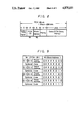
- FIG. 9 is a table showing formats of symbols W 1 and W 2 in a PCM block.
- FIG. 10 is a circuit block diagram showing a practical example of the reproduced signal processing circuit appearing in FIG. 6.
- a conventional system as disclosed in Japanese Laid-open Patent Publication No. 59-2205, requires the rotary heads 3A and 3B to be mounted substantially at the same position on the rotary drum so as to make constant the width of tracks on which signals are recorded.
- the rotary heads 3A and 3B can be mounted at more desirable positions on the periphery of the rotary drum since the difference between the traces by the rotary heads 3A and 3B does not cause any problem. Therefore, in the present invention, as shown in FIG. 3, the rotary heads 3A and 3B are mounted on the periphery of the rotary drum 2 with an angular distance of 180° so that the two rotary heads 3A and 3B are diametrically opposed.
- the normal tracking system has an error rate to tracking error characteristic as shown in FIG. 4.
- the no-tracking system can always reduce the error rate to below f(0) totally, regardless of the head mounting position, if the rotary heads are rotated at a speed twice the ordinary recording speed to scan tracks at more than twice the normal recording speed and read signals at more than twice the normal recording speed.
- FIG. 6 shows the circuit arrangement of an apparatus according to the present invention which reproduces a signal recorded on a tape by an ordinary R-DAT.
- a reference diameter for an ordinary DAT would be 30 mm.
- a rotary drum 2 the diameter of which is half that of the ordinary R-DAT, e.g., 15 mm, is rotated at a speed twice the normal speed of the R-DAT, e.g., 4000 rpm.
- a pair of rotary heads 3A and 3B are mounted on the periphery of the rotary drum 2 with an angular distance of 180°.
- a magnetic tape MT is obliquely wrapped around the outer periphery of the rotary drum 2 with a wrap angle of 180°.
- the apparatus may also be considered in which, if the diameter of the rotary drum 2 is 30 mm, the tapewrap angle is selected to be 90° and the rotary drum 2 is rotated at a speed twice the normal speed of the R-DAT, that is, 4000 rpm.
- the magnetic tape MT is stretched between a reel hub 4 and the other reel hub 5 provided in a tape cassette and transported at the predetermined normal speed of the R-DAT by a capstan 6 and a pinch roller 7.
- the rotary drum having a pair of heads mounted with an angular distance of 180° on the periphery thereof has a diameter of 30 mm and is rotated at 2000 rpm.
- the magnetic tape is wrapped around the outer periphery of the rotary drum with a wrap angle of 90°.
- the rotary heads 3A and 3B are alternately selected by a change-over switch 8. Signals reproduced by the respective rotary heads 3A and 3B are supplied to a reproducing amplifier 9 through a rotary transformer and a head amplifier (both not shown). A control signal for controlling the switch 8 is generated by a timing control circuit 10.
- the reproduced signals are transmitted at a transmitting speed twice the transmitting speed of the ordinary R-DAT since the rotary heads are rotated at 4000 rpm, that is, a rotational speed twice the rotational speed of the normal R-DAT.
- the respective tracks formed on the tape are also scanned at twice the scanning rate of the normal R-DAT. Therefore, the rotary heads trace the tracks with an interval half that of the track recorded on the tape.
- An output signal from the reproducing amplifier 9 is supplied to a phase locked loop (PLL) circuit 11 wherein a clock signal in synchronism with the reproduced signal is extracted.
- Signal processing such as error correction, interpolation and so on are effected for the reproduced signal in a reproduced signal processing circuit 12.
- the reproduced and processed digital audio signal is supplied to a digital to analog (D/A) converter 13.
- the reproduced audio signal from the D/A converter 13 is delivered to an output terminal 15 through a low pass filter 14.
- a sub-code and a sub-code ID are separated from the reproduced signal and are then delivered to an output terminal 16.
- To the output terminal 16 there is connected a sub-code decoder (not shown) which generates control data and so on from the sub-code.
- the timing control circuit 10 generates a clock signal and a timing signal which are required by the reproducing signal processing circuit 12.
- FIG. 7 shows the construction of the data recorded in one segment by one of the rotary heads. If a unit amount of the recorded data is determined as “one block", one segment includes the data of 196 blocks (corresponding to 7500 ⁇ sec). At both side end portions of one segment corresponding to both side end portions of the track there are respectively provided margins (11 blocks). Sub-codes 1 and 2 (eight blocks) are respectively recorded in portions adjacent to the margins. The contents of the two subcodes 1 and 2 are the same, namely, the same data is double-recorded. The sub-codes may be a program number, a time code, a start identifying signal and so on. At both sides of each of the eight block sub-code recording areas 1 and 2, a PLL run-in interval or portion (two blocks) and a postamble interval or portion (one block) are respectively located.
- inter-block gaps three blocks in which no data is recorded.
- a pilot signal for the ATF is recorded in two ATF regions of five blocks which are respectively located at portions between two inter-block gaps.
- the processed PCM signals are recorded in a central region having a length of 130 blocks in one segment except for the PLL run-in portion of two blocks, that is, in a 128 block length region.
- the PCM signals of two segments correspond to audio signals read by the rotary heads during one rotation thereof.
- the PCM signal comprises two-channel stereo PCM signals consisting of a L (left) channel and a R (right) channel signals and parity data consisting of error detection and error correction codes.
- data L e is recorded in the left half of the PCM signal recording region and data R o in the right half of the same.
- the data L e comprises even-numbered data of the L channel and a parity code for correcting possible errors occurring in the data L e
- the data R o comprises odd-numbered data of the R channel and a parity code for correcting possible errors occurring in the data R o .
- Each number of the odd-and even-number indicates a number counted from the head of the interleave block.
- One segment of data formed in the same manner as described above is recorded in a track formed by the other rotary head.
- the data region of one segment in one track formed by the other rotary head is divided into the left half portion for recording data R e and the right half portion for recording data L o .
- the data R e comprises even-numbered data of the R channel and a parity code for correcting possible errors occurring in the data R e .
- the data L o comprises odd-numbered data of the L channel and a parity code for correcting possible errors occurring in the data L o .
- FIG. 8 shows the data construction of one block of the PCM signal.
- a block synchronizing signal having an eight bit length (eight bits are referred to as "one symbol") is allocated, which is followed by a PCM-ID (referred to as "W 1 ”) of eight bits and a block address portion (referred to as "W 2 ”) of eight bits.
- An error correction coding by a simple parity is effected with regard to the two symbols of the PCM-ID (W 1 ) and the block address portion (W 2 ) and a parity code of eight bits is added after the block address.
- the block address portion is constituted by seven bits except the most significant bit (MSB).
- MSB is set to "0" to indicate that the block is a PCM block.
- the block address indicated by seven bits changes sequentially from (00) to (7F) in hexadecimal.
- the PCM-ID indicative of data recorded in each block is recorded in locations, the block addresses of which are (000), (010), (100) or (110) in the lower three bits.
- Optional codes of the PCM-ID can be recorded in locations, the block addresses of which are (001), (011), (101) or (111) in the lower three bits.
- the PCM-ID includes two bits of ID-1 to ID-8 and four bits of frame address.
- the respective ID-1 to ID-7 respectively show identifying information.
- a pack or packet is formed of 32 ID-8s (two bits). For example, ID-1, which is a format ID, indicates whether recorded data is for audio or for any other purposes.
- ID-2 indicates on or off of pre-emphasis and the characteristics of the pre-emphasis
- ID-3 a sampling frequency.
- the above-mentioned ID-1 to ID-7 and frame address are recorded equally in two segments constituting an interleave pair. In other words, the frame address is incremented by one at every two segments.
- the reproduced signal is supplied by way of a terminal 21 to a demodulating circuit 22 wherein one symbol formed of ten bits is demodulated to one symbol formed of eight bits. Eight bits of one symbol have been digitally modulated to a suitable pattern of ten bits upon being recorded on the magnetic tape MT so as to reduce low frequency components suitably.
- the reproduced data from the demodulating circuit 22 is delivered symbol by symbol through a data register 23 to a data bus 24.
- the data bus 24 is connected with a buffer RAM 25 and an error correction circuit 26.
- the buffer RAM 25 should have a capacity larger than that of the buffer RAM provided in an ordinary R-DAT, which generally has a capacity for storing data recorded in four tracks, since it is required to store in the buffer RAM 25 data reproduced by the rotary heads which possibly overlap tracks due to omission of the tracking control.
- the block address and the frame address of the reproduced signal from the signal outputted from the demodulating circuit 22 are detected by an address detecting circuit 27 and supplied to an address control circuit 28.
- the output signal from the address control circuit 28 is supplied to the buffer RAM 25 as an address signal.
- the reproduced data is stored via the data bus 24 in the buffer RAM 25 in accordance with the address signal from the address control circuit 28.
- the reproduced data is stored in the buffer RAM 25 in accordance with the block address and the frame address without tracking control.
- error correction is effected by a Reed-Solomon code on each track of data stored in the buffer RAM 25.
- the reproduced data after being subjected to the error correction, is read out of the buffer RAM 25 in the original order and the error-corrected PCM signal is supplied to an interpolation circuit 29 wherein uncorrectable errors are interpolated.
- the reproduced PCM signal is then supplied through an output terminal 30 to the D/A converter 13 shown in FIG. 6.
- the sub-code is delivered to a sub-code output terminal after processing, such as error correction, in the sub-code decoder (not shown).
- the tapewrap angle is selected to be less than 180° in order that the rotary heads 3A and 3B will not be simultaneously in contact with a tape
- the rotational speed of the rotary drum 2 is selected to be twice the recording speed of the ordinary R-DAT, so that the number of sets of the reproducing amplifier 9, the PLL circuit 11, the reproduced signal processing circuit 12 and so on can be reduced to one set without the necessity of the tracking control.
- the tapewrap angle is selected to be less than 360°/n with respect to the number n of rotary heads mounted on the periphery of the rotary drum and a plurality of rotary heads will not be in contact with a tape at the same time.
- the arrangement of the reproducing circuit can be simplified, and consequently the production cost can be reduced.
Landscapes
- Engineering & Computer Science (AREA)
- Signal Processing (AREA)
- Multimedia (AREA)
- Digital Magnetic Recording (AREA)
- Signal Processing For Digital Recording And Reproducing (AREA)
- Adjustment Of The Magnetic Head Position Track Following On Tapes (AREA)
- Electrophonic Musical Instruments (AREA)
- Control Of Electric Motors In General (AREA)
Applications Claiming Priority (2)
| Application Number | Priority Date | Filing Date | Title |
|---|---|---|---|
| JP61196020A JPH083882B2 (ja) | 1986-08-21 | 1986-08-21 | デイジタル信号再生装置 |
| JP61-196020 | 1986-08-21 |
Publications (1)
| Publication Number | Publication Date |
|---|---|
| US4875111A true US4875111A (en) | 1989-10-17 |
Family
ID=16350884
Family Applications (1)
| Application Number | Title | Priority Date | Filing Date |
|---|---|---|---|
| US07/087,093 Expired - Lifetime US4875111A (en) | 1986-08-21 | 1987-08-19 | Apparatus for reproducing a digital signal |
Country Status (7)
| Country | Link |
|---|---|
| US (1) | US4875111A (de) |
| EP (1) | EP0257991B1 (de) |
| JP (1) | JPH083882B2 (de) |
| KR (1) | KR960000450B1 (de) |
| AT (1) | ATE74459T1 (de) |
| CA (1) | CA1307586C (de) |
| DE (1) | DE3777916D1 (de) |
Cited By (4)
| Publication number | Priority date | Publication date | Assignee | Title |
|---|---|---|---|---|
| US5223994A (en) * | 1989-10-02 | 1993-06-29 | Behr Michael I | System using superimposed, orthogonal buried servo signals |
| US5276561A (en) * | 1989-07-28 | 1994-01-04 | Sony Corporation | Apparatus for reproducing digital signal |
| US5321570A (en) * | 1989-10-02 | 1994-06-14 | Behr Michael I | Systems using superimposed, orthogonal buried servo signals |
| US6736585B2 (en) * | 2001-05-15 | 2004-05-18 | G & H Manufacturing, Ltd. | Container safety latch |
Families Citing this family (2)
| Publication number | Priority date | Publication date | Assignee | Title |
|---|---|---|---|---|
| US5091805A (en) * | 1987-10-27 | 1992-02-25 | Sony Corporation | Apparatus and method for recording and/or reproducing a digital signal |
| JP2822507B2 (ja) * | 1989-11-25 | 1998-11-11 | ソニー株式会社 | ディジタル信号記録装置 |
Citations (14)
| Publication number | Priority date | Publication date | Assignee | Title |
|---|---|---|---|---|
| US3157738A (en) * | 1961-10-24 | 1964-11-17 | Okamura Shiro | Standards conversion for television signals |
| DE1474487A1 (de) * | 1964-08-01 | 1969-09-04 | Sony Corp | Aufzeichen- und Wiedergabesystem |
| US4282551A (en) * | 1979-04-11 | 1981-08-04 | Hitachi, Ltd. | PCM Recording and reproducing apparatus |
| US4346397A (en) * | 1978-01-23 | 1982-08-24 | Victor Company Of Japan, Ltd. | Apparatus for reproducing a video signal of one system with conversion to a video signal of another system |
| EP0115699A1 (de) * | 1982-12-27 | 1984-08-15 | Sony Corporation | Verfahren und Vorrichtung zur Aufnahme und Wiedergabe von analogen Signalen |
| US4510538A (en) * | 1981-12-14 | 1985-04-09 | Sony Corporation | Magnetic recording apparatus |
| EP0178905A2 (de) * | 1984-10-15 | 1986-04-23 | Pioneer Electronic Corporation | Magnetisches Aufnahme- und Wiedergabegerät |
| EP0178589A2 (de) * | 1984-10-17 | 1986-04-23 | Hitachi, Ltd. | Verfahren und Anordnung zur Aufzeichnung von PCM-Signalen |
| EP0191469A2 (de) * | 1985-02-14 | 1986-08-20 | Sony Corporation | Aufzeichnungs- und/oder Wiedergabegerät für Tonsignale |
| US4617599A (en) * | 1983-06-15 | 1986-10-14 | Hitachi, Ltd. | PCM signal recording/reproducing apparatus |
| US4626932A (en) * | 1983-02-26 | 1986-12-02 | Robert Bosch Gmbh | Rotating video head switching control system |
| US4628373A (en) * | 1983-06-10 | 1986-12-09 | Hitachi, Ltd. | Rotating head type magnetic record/reproduce apparatus |
| US4670796A (en) * | 1983-06-29 | 1987-06-02 | Hitachi, Ltd. | Rotary head type PCM recorder |
| US4675754A (en) * | 1984-02-21 | 1987-06-23 | Mitsubishi Denki Kabushiki Kaisha | Magnetic recorder/reproducer |
Family Cites Families (2)
| Publication number | Priority date | Publication date | Assignee | Title |
|---|---|---|---|---|
| JPS6010404A (ja) * | 1983-06-29 | 1985-01-19 | Hitachi Ltd | 回転ヘツド型pcmレコ−ダ |
| JPS6044203U (ja) * | 1983-09-03 | 1985-03-28 | 日本ビクター株式会社 | 回転ヘッド型pcm磁気記録再生装置 |
-
1986
- 1986-08-21 JP JP61196020A patent/JPH083882B2/ja not_active Expired - Lifetime
-
1987
- 1987-08-19 US US07/087,093 patent/US4875111A/en not_active Expired - Lifetime
- 1987-08-19 KR KR1019870009032A patent/KR960000450B1/ko not_active Expired - Fee Related
- 1987-08-20 DE DE8787307380T patent/DE3777916D1/de not_active Expired - Lifetime
- 1987-08-20 CA CA000544985A patent/CA1307586C/en not_active Expired - Lifetime
- 1987-08-20 AT AT87307380T patent/ATE74459T1/de not_active IP Right Cessation
- 1987-08-20 EP EP87307380A patent/EP0257991B1/de not_active Expired - Lifetime
Patent Citations (15)
| Publication number | Priority date | Publication date | Assignee | Title |
|---|---|---|---|---|
| US3157738A (en) * | 1961-10-24 | 1964-11-17 | Okamura Shiro | Standards conversion for television signals |
| DE1474487A1 (de) * | 1964-08-01 | 1969-09-04 | Sony Corp | Aufzeichen- und Wiedergabesystem |
| US4346397A (en) * | 1978-01-23 | 1982-08-24 | Victor Company Of Japan, Ltd. | Apparatus for reproducing a video signal of one system with conversion to a video signal of another system |
| US4282551A (en) * | 1979-04-11 | 1981-08-04 | Hitachi, Ltd. | PCM Recording and reproducing apparatus |
| US4510538A (en) * | 1981-12-14 | 1985-04-09 | Sony Corporation | Magnetic recording apparatus |
| US4544958A (en) * | 1982-12-27 | 1985-10-01 | Sony Corporation | High-speed recording and reproducing of signals |
| EP0115699A1 (de) * | 1982-12-27 | 1984-08-15 | Sony Corporation | Verfahren und Vorrichtung zur Aufnahme und Wiedergabe von analogen Signalen |
| US4626932A (en) * | 1983-02-26 | 1986-12-02 | Robert Bosch Gmbh | Rotating video head switching control system |
| US4628373A (en) * | 1983-06-10 | 1986-12-09 | Hitachi, Ltd. | Rotating head type magnetic record/reproduce apparatus |
| US4617599A (en) * | 1983-06-15 | 1986-10-14 | Hitachi, Ltd. | PCM signal recording/reproducing apparatus |
| US4670796A (en) * | 1983-06-29 | 1987-06-02 | Hitachi, Ltd. | Rotary head type PCM recorder |
| US4675754A (en) * | 1984-02-21 | 1987-06-23 | Mitsubishi Denki Kabushiki Kaisha | Magnetic recorder/reproducer |
| EP0178905A2 (de) * | 1984-10-15 | 1986-04-23 | Pioneer Electronic Corporation | Magnetisches Aufnahme- und Wiedergabegerät |
| EP0178589A2 (de) * | 1984-10-17 | 1986-04-23 | Hitachi, Ltd. | Verfahren und Anordnung zur Aufzeichnung von PCM-Signalen |
| EP0191469A2 (de) * | 1985-02-14 | 1986-08-20 | Sony Corporation | Aufzeichnungs- und/oder Wiedergabegerät für Tonsignale |
Non-Patent Citations (8)
| Title |
|---|
| "Exclusive Test Report Four DAT Recorders", L. Feldman, Audio, Jul. 1987, pp. 36-47. |
| "Rotating Digital Audio Tape (R--DAT): A Format Overview", P. A. Dare and R. Katsumi, SMPTE Journal, Oct. 1987, pp. 943-948. |
| "Servo Technology of R--DAT", A Hitomi and T. Taki, IEEE Transcations on Consumer Electronics, vol. CE--32, No. 3, Aug. 1986, pp. 425-432. |
| "The DAT Conference, Its Activities and Results", H. Nakajima and M. Kosaka, IEEE Transactions on Consumer Electronics, vol. CE--32, No. 3, Aug. 1986, pp. 404-415. |
| Exclusive Test Report Four DAT Recorders , L. Feldman, Audio, Jul. 1987, pp. 36 47. * |
| Rotating Digital Audio Tape (R DAT): A Format Overview , P. A. Dare and R. Katsumi, SMPTE Journal, Oct. 1987, pp. 943 948. * |
| Servo Technology of R DAT , A Hitomi and T. Taki, IEEE Transcations on Consumer Electronics, vol. CE 32, No. 3, Aug. 1986, pp. 425 432. * |
| The DAT Conference, Its Activities and Results , H. Nakajima and M. Kosaka, IEEE Transactions on Consumer Electronics, vol. CE 32, No. 3, Aug. 1986, pp. 404 415. * |
Cited By (4)
| Publication number | Priority date | Publication date | Assignee | Title |
|---|---|---|---|---|
| US5276561A (en) * | 1989-07-28 | 1994-01-04 | Sony Corporation | Apparatus for reproducing digital signal |
| US5223994A (en) * | 1989-10-02 | 1993-06-29 | Behr Michael I | System using superimposed, orthogonal buried servo signals |
| US5321570A (en) * | 1989-10-02 | 1994-06-14 | Behr Michael I | Systems using superimposed, orthogonal buried servo signals |
| US6736585B2 (en) * | 2001-05-15 | 2004-05-18 | G & H Manufacturing, Ltd. | Container safety latch |
Also Published As
| Publication number | Publication date |
|---|---|
| CA1307586C (en) | 1992-09-15 |
| EP0257991B1 (de) | 1992-04-01 |
| KR880003317A (ko) | 1988-05-16 |
| JPH083882B2 (ja) | 1996-01-17 |
| EP0257991A3 (en) | 1989-05-10 |
| JPS6352306A (ja) | 1988-03-05 |
| DE3777916D1 (de) | 1992-05-07 |
| EP0257991A2 (de) | 1988-03-02 |
| ATE74459T1 (de) | 1992-04-15 |
| KR960000450B1 (ko) | 1996-01-06 |
Similar Documents
| Publication | Publication Date | Title |
|---|---|---|
| EP0237020B1 (de) | Verfahren und Gerät zum Übertragen und Empfangen eines Digitalsignals | |
| KR0180544B1 (ko) | 디지탈신호의 기록재생 방법 및 장치 | |
| EP0235782B1 (de) | Digitalwiedergabegerät | |
| EP0209047B1 (de) | Gerät zum Auzeichnen und/oder Wiedergeben eines Informationssignales | |
| EP0234577B1 (de) | Dekodiergerät | |
| EP0278702B1 (de) | Verfahren zur Wiedergabe eines digitalen Signals | |
| US4875111A (en) | Apparatus for reproducing a digital signal | |
| US5559644A (en) | Data recording/reproducing apparatus having a first error correcting code on both sides of a main data area of each azimuth track | |
| US5430741A (en) | Repeated decoding of product code during successive tape head rotation periods | |
| US5276561A (en) | Apparatus for reproducing digital signal | |
| JP2597989B2 (ja) | データ再生装置 | |
| JP2505470B2 (ja) | 回転ヘッド形磁気記録再生装置 | |
| EP0410897B1 (de) | Gerät zur Wiedergabe von digitalen Signalen | |
| JP3023580B2 (ja) | 磁気記録装置 | |
| JPS62204406A (ja) | 回転ヘツド型デイジタルテ−プレコ−ダ | |
| JPS62204470A (ja) | 同期検出装置 | |
| JPH05234275A (ja) | ディジタル信号再生装置 |
Legal Events
| Date | Code | Title | Description |
|---|---|---|---|
| AS | Assignment |
Owner name: SONY CORPORATION, 7-35 KITASHINAGAWA-6, SHINAGAWA- Free format text: ASSIGNMENT OF ASSIGNORS INTEREST.;ASSIGNORS:ODAKA, KENTARO;FUKAMI, TADASHI;OZAKI, SHINYA;REEL/FRAME:004766/0667 Effective date: 19870813 Owner name: SONY CORPORATION, A CORP. OF JAPAN,JAPAN Free format text: ASSIGNMENT OF ASSIGNORS INTEREST;ASSIGNORS:ODAKA, KENTARO;FUKAMI, TADASHI;OZAKI, SHINYA;REEL/FRAME:004766/0667 Effective date: 19870813 |
|
| STCF | Information on status: patent grant |
Free format text: PATENTED CASE |
|
| FEPP | Fee payment procedure |
Free format text: PAYOR NUMBER ASSIGNED (ORIGINAL EVENT CODE: ASPN); ENTITY STATUS OF PATENT OWNER: LARGE ENTITY |
|
| FPAY | Fee payment |
Year of fee payment: 4 |
|
| SULP | Surcharge for late payment | ||
| REMI | Maintenance fee reminder mailed | ||
| FPAY | Fee payment |
Year of fee payment: 8 |
|
| FPAY | Fee payment |
Year of fee payment: 12 |