US4823366A - Material conveying equipment with control for paving materials using ultrasonic waves - Google Patents
Material conveying equipment with control for paving materials using ultrasonic waves Download PDFInfo
- Publication number
- US4823366A US4823366A US07/014,991 US1499187A US4823366A US 4823366 A US4823366 A US 4823366A US 1499187 A US1499187 A US 1499187A US 4823366 A US4823366 A US 4823366A
- Authority
- US
- United States
- Prior art keywords
- paving material
- signal
- paving
- circuit
- control
- Prior art date
- Legal status (The legal status is an assumption and is not a legal conclusion. Google has not performed a legal analysis and makes no representation as to the accuracy of the status listed.)
- Expired - Lifetime
Links
- 239000000463 material Substances 0.000 title claims abstract description 89
- 239000003990 capacitor Substances 0.000 claims description 28
- 230000000977 initiatory effect Effects 0.000 claims description 9
- 230000005540 biological transmission Effects 0.000 claims description 6
- 230000004044 response Effects 0.000 claims description 6
- 230000010354 integration Effects 0.000 claims description 5
- 230000005855 radiation Effects 0.000 claims description 5
- 238000002592 echocardiography Methods 0.000 claims description 3
- 230000002401 inhibitory effect Effects 0.000 claims description 2
- 238000004519 manufacturing process Methods 0.000 claims description 2
- 238000002604 ultrasonography Methods 0.000 claims 4
- 238000007599 discharging Methods 0.000 claims 2
- 230000007274 generation of a signal involved in cell-cell signaling Effects 0.000 claims 1
- 239000013590 bulk material Substances 0.000 abstract description 6
- 239000010426 asphalt Substances 0.000 description 29
- 238000010586 diagram Methods 0.000 description 6
- 230000000694 effects Effects 0.000 description 4
- 238000005299 abrasion Methods 0.000 description 2
- 238000005056 compaction Methods 0.000 description 2
- 238000010276 construction Methods 0.000 description 2
- 230000007613 environmental effect Effects 0.000 description 2
- 230000036039 immunity Effects 0.000 description 2
- 238000009434 installation Methods 0.000 description 2
- 230000004048 modification Effects 0.000 description 2
- 238000012986 modification Methods 0.000 description 2
- 208000027418 Wounds and injury Diseases 0.000 description 1
- 230000006978 adaptation Effects 0.000 description 1
- 230000002411 adverse Effects 0.000 description 1
- XAGFODPZIPBFFR-UHFFFAOYSA-N aluminium Chemical compound [Al] XAGFODPZIPBFFR-UHFFFAOYSA-N 0.000 description 1
- 229910052782 aluminium Inorganic materials 0.000 description 1
- 230000008901 benefit Effects 0.000 description 1
- 238000009933 burial Methods 0.000 description 1
- 230000008859 change Effects 0.000 description 1
- 230000006378 damage Effects 0.000 description 1
- 239000006260 foam Substances 0.000 description 1
- 208000014674 injury Diseases 0.000 description 1
- 230000009467 reduction Effects 0.000 description 1
- 230000002829 reductive effect Effects 0.000 description 1
- 230000000284 resting effect Effects 0.000 description 1
- 230000035939 shock Effects 0.000 description 1
- 230000011664 signaling Effects 0.000 description 1
- 230000001629 suppression Effects 0.000 description 1
Images




Classifications
-
- E—FIXED CONSTRUCTIONS
- E01—CONSTRUCTION OF ROADS, RAILWAYS, OR BRIDGES
- E01C—CONSTRUCTION OF, OR SURFACES FOR, ROADS, SPORTS GROUNDS, OR THE LIKE; MACHINES OR AUXILIARY TOOLS FOR CONSTRUCTION OR REPAIR
- E01C19/00—Machines, tools or auxiliary devices for preparing or distributing paving materials, for working the placed materials, or for forming, consolidating, or finishing the paving
- E01C19/004—Devices for guiding or controlling the machines along a predetermined path
- E01C19/006—Devices for guiding or controlling the machines along a predetermined path by laser or ultrasound
-
- E—FIXED CONSTRUCTIONS
- E01—CONSTRUCTION OF ROADS, RAILWAYS, OR BRIDGES
- E01C—CONSTRUCTION OF, OR SURFACES FOR, ROADS, SPORTS GROUNDS, OR THE LIKE; MACHINES OR AUXILIARY TOOLS FOR CONSTRUCTION OR REPAIR
- E01C19/00—Machines, tools or auxiliary devices for preparing or distributing paving materials, for working the placed materials, or for forming, consolidating, or finishing the paving
- E01C19/48—Machines, tools or auxiliary devices for preparing or distributing paving materials, for working the placed materials, or for forming, consolidating, or finishing the paving for laying-down the materials and consolidating them, or finishing the surface, e.g. slip forms therefor, forming kerbs or gutters in a continuous operation in situ
-
- E—FIXED CONSTRUCTIONS
- E01—CONSTRUCTION OF ROADS, RAILWAYS, OR BRIDGES
- E01C—CONSTRUCTION OF, OR SURFACES FOR, ROADS, SPORTS GROUNDS, OR THE LIKE; MACHINES OR AUXILIARY TOOLS FOR CONSTRUCTION OR REPAIR
- E01C2301/00—Machine characteristics, parts or accessories not otherwise provided for
- E01C2301/14—Extendable screeds
- E01C2301/16—Laterally slidable screeds
Definitions
- This invention relates to a feed control arrangement for bulk materials, and is especially directed to arrangements for improving the feeding of rotating materials, such as asphalt or other materials in road pavers, wideners, etc. While the invention will be described with particular reference to such applications, it will be apparent that the concept of the invention, as discussed herein, is not so limited.
- paving material such as asphalt is fed rearwardly on the equipment, for example by a conveyor chain or the like, as the equipment is moved forwardly along a road or road bed, the paving material being fed to a device for distributing the material transversely, such as an auger in the case of a paving device, or a belt in the case of road widening equipment.
- the paving material is deposited in front of a screed, which may be a floating screed, to effect the leveling and compaction of the material.
- Typical paving devices are disclosed, for example, in U.S. Pat. No. 3,584,547, Davin, and typical road wideners are disclosed, for example, in U.S. Pat. No. 3,636,831, Davin et al.
- Paddle controlled potentiometers directly contacting the hot asphalt, were employed primarily in view of the extremely adverse conditions for the sensing of the height of the top level of the asphalt.
- any sensing arrangement must be capable of functioning properly under conditions of extreme temperature variation, as well as being resistant to abrasion and shock. It has further been heretofor considered necessary that the sensing arrangement not be sensitive to local conditions other than the height of the material. The fact that the sensing devices are employed on road making equipment thereby necessitates that they be extremely rugged.
- paddle controlled potentiometers of the type disclosed in U.S. Pat. No. 3,678,817 provided the only satisfactory solution in paving equipment. As above discussed, however, the provision of paddles physically contacting the asphalt, generally in regions adjacent the ends of the augers, does not provide an optimum solution to the problem.
- the present invention is therefore directed to the provision of an improved sensing arrangement for bulk material conveying equipment, especially road equipment such as pavers, which overcomes the above discussed problems of prior arrangements.
- a sensing arrangement for bulk material conveying equipment such as pavers or the like, wherein the sensing arrangement comprises a non-contacting sensor fixedly mounted to the equipment, for sensing the distance between the level of the bulk material and the sensor.
- the remote location of the sensing device from the bulk material reduces the requirements of the sensing device to withstand extreme environmental conditions, the sensing device thus no longer being subject to the heat of the asphalt or to abrasion from the material.
- the provision of the remote sensing device in accordance with the invention further prevents the outputting of erroneous control signals due, for example, to buildup of the material on the sensor, or to actual burying of the sensing device within the material.
- non-contacting sensing arrangements not only overcome the above discussed disadvantages of prior arrangements, but also provide satisfactory performance under the extremely harsh environmental conditions as required.
- ultrasonic sensing arrangements are especially useful in accordance with the invention, in particular for road paving equipment
- the invention also contemplates other remote sensing arrangements of known types, for example, employing light or other radiation to determine the distance between the sensor and the paving material, for example by triangulation.
- the invention thereby enables the more accurate automatic control of material height, and is especially useful in equipment such as paving machines wherein control of this parameter is essential in the use of the equipment.
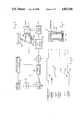
- FIG. 1 is a simplified side view of a paving machine incorporating the invention, the paving machine being illustrated partially in section;
- FIG. 2 is a simplified top view of a portion of a paving machine with extendable screeds, illustrating the adaptation of the sensing arrangement of the invention to such a device;
- FIG. 3 is a simplified block diagram of a sensing arrangement in accordance with one embodiment of the invention, for application to a paving machine;
- FIG. 4 is a simplified cross sectional view of a sensing head that may be employed in the arrangement of FIG. 3 as well as in the arrangement of FIG. 6;
- FIG. 5 illustrates various timing signals for the circuit of FIG. 3
- FIG. 6 is a more detailed circuit of a preferred embodiment of the invention.
- FIG. 7 illustrates various timing wave forms of the circuit of FIG. 6.
- FIG. 1 illustrates a paving machine having a frame 10 with a hopper 11 for receiving paving material and a body 12 mounted thereon.
- the paving machine is adapted to move on endless tracks 13 although it is apparent that it may alternatively be mounted to move on wheels (not shown).
- a screed 14 is supported pivotally rearwardly of the frame by a screed arm 15.
- Paving material deposited in the hopper 11 is conveyed by a conveyor (not illustrated) in FIG. 1, to a transversely extending auger 16 in front of the screed, the paving material 17 being transversely distributed by the auger 16 for compaction in a layer of even thickness by the screed 14.
- the paving machine illustrated in FIG. 1 may thus be, for example, a device of the type disclosed in U.S. Pat. No. 3,700,288.
- a sensor for example, an ultrasonic sensor 20 is mounted to the paving machine, or screed, and directed in the direction of arrow 21 to sense the top surface of the paving material 17.
- the sensor 21, which may be comprised of an ultrasonic transducer as will be disclosed in greater detail in the following paragraphs, may be rigidly affixed to the paving machine, and preferably separate such transducers are provided at each side of the paving machine to sense the height of the top surface of the paving material adjacent each end of the auger 16. While the drawing illustrates the sensing of the height of the paving material immediately to the front of the auger, it will be apparent that the transducer may be directed to sense the height of the top surface of the paving material at any other convenient location.
- the transducer 20 is connected to provide an output signal corresponding to the time of travel of sound waves between the transducer and the top surface of the paving material, this distance hence constituting a measure of the distance between the transducer and the surface 22 upon which the paving machine is driven, and, hence, the thickness of the paving material in front of the screed.
- FIG. 1 thus illustrates generally the sensing arrangement in accordance with the invention, and its relationship to the paving machine in general.
- the paving material piled in front of the screed directs forces onto the screed in known manner, whereby the angular orientation of the screed, and hence the thickness of the compacted layer 23 behind the screed, may vary as a function of the amount of material in front of the screed.
- FIG. 2 illustrates a simplified top view of a portion of a paving machine having a telescoping screed, for example, of the type disclosed in U.S. Pat. No. 4,379,653.
- the paving material is conveyed on a conveyor 30, in the direction of arrow 31, to a rotatable auger 32 extending transversely of the direction of movement (arrow 33) of the paving machine.
- the paving machine is provided with a pair of fixed main screeds 34 rearwardly of the auger, and a pair of laterally movable screeds 35 in front of the main screeds, the extendable screeds being movable in the directions of the arrows 36.
- End plates 37 are affixed to the lateral extremities of the extendable screeds.
- the non-contacting sensors or transducers 38 in accordance with the invention are mounted above and to the front of the ends of the auger 32, to detect the height of the paving material in this region.
- the control signals obtained from the sensing devices are employed to control the speed of rotation of the drive 39 of the auger and/or the speed of movement of the conveyor 30 and/or the height of a gate for passing material along the hopper as disclosed, for example, in U.S. Pat. No. 3,678,817.
- FIG. 2 thus illustrates further, in a simplified manner, the application of the non-contacting sensors or transducers of the invention to a paving machine.
- FIG. 3 is a simplified block diagram of one embodiment of a feed control arrangement of the invention, especially adapted for a paving machine or the like.
- a master clock 40 applies timing signals to a transmit/receive device 41 coupled to a transducer 42.
- the transducer may be an ultrasonic transducer.
- the transmit/receive device 41 hence comprises a circuit responsive to the control signals from the master clock for energizing the transducer to transmit an ultrasonic pulse.
- the transmit/receive device also receives echo signals responsive to the receipt of ultrasonic echoes by the transducer 42, for applying an echo responsive signal to a logic circuit 43 by way of a control line 44.
- the ultrasonic pulses are directed to the paving material such as asphalt 45 forwardly of the auger 46 of the paving machine, so that the elapsed time between the pulse transmitted by the transducer 42 and the ultrasonic echo pulse received by the transducer 42 is a function of the distance between the transducer 42 and the top surface of the asphalt.
- the transducer 42 is adapted to be fixedly mounted to the paving machine, or screed, so that this time delay is also a measure of the height of the top surface of the asphalt, and hence of the thickness of the asphalt layer.
- the transducer 42 may be a commercially available ultrasonic transducer fixedly mounted in an open-ended plastic housing 50 for installation and support, the plastic housing 50 being fixedly mounted in an aluminum housing 51 for mechanical strength, the housing 51 being shaped as desired to enable its ready mounting to the paving machine.
- the open end of the plastic housing 50 is covered with a layer 52 of acoustically transparent foam, protected by an external layer 53 of screen wire.
- the transducer 42 may be Electrostatic Transducer no. 604142 manufactured by the Polaroid Corporation.
- the output of the master clock 40 is also applied to a divider or counter circuit 55 for producing a plurality of timing signals for the logic circuits 43.
- the logic circuit upon receipt of a signal either from the divider 55 or the transmit/receive device 41, signalling the energization of the transducer, provides a control circuit for a ramp generator 56 to initiate a ramp signal.
- the time of the initiation of the ramp signal with respect to the time of the transmit pulse, may be controlled in order that the interval during which the ramp signal occurs, correspond to a determined range of thicknesses of the asphalt.
- the logic circuit opens a gate 57 to pass the instantaneous amplitude of the ramp signal to an integrater and power amplifier 58.
- the logic circuit 43 further controls the suppression of the ramp signal when no echo is received within a predetermined range of interest.
- the echo signal may occur prior to the initiation of the ramp, in which case a zero or low level signal is applied to the integrater.
- the ramp generator may have a maximum ramp level, attained after a given time following its energization, so that this maximum level is passed to the integrater in response to the receipt of an echo signal after the attaining of its full level by the ramp generator.
- line A illustrates an enable signal from the master clock to the transmit/receive device 41 controlling the device 41 to transmit the ultrasonic pulse 60 as illustrated on line B.
- the logic circuit may develop a listen gate 61, as illustrated in line C, during which time the logic circuit 43 is responsive to the receipt of echo pulses from the device 41, as illustrated on line E, the time 64 being a predetermined time following the initiation of the transmit pulse 60.
- the generation of the aforementioned ramp signal 63 ceases as shown on line E, and the gate 57 is opened by the logic circuit 43, as illustrated by the rise at 66 of line F, to pass the then occurring signal level of the ramp to the integrater and power amplifier 58.
- the integrater and power amplifier 58 integrates the received signal over a number of cycles, for example, about 10 pulses of ultrasonic energy, in order to avoid erroneous output signals resulting from such conditions, for example, as uneven surfaces of the asphalt or vibration of the transducer.
- the intermediate signals are amplified and applied to a motor speed control device 69 for controlling the auger motor 70.
- the motor speed control 69 may conventionally constitute a torque motor on a servo valve, for controlling the speed of rotation of the motor 70, when an hydraulic motor is employed.
- the ramp 63 is positioned in the timing diagram to occur when the top of the sensed asphalt is within a determined range of distances from the transducer in which variable speed control of the auger motor is to be effected. This range may be, for example, about 2 inches.
- the maximum signal level is passed to the integrater, and the motor speed control 69 controls the motor to its fastest speed rate.
- the motor speed control 69 may, of course, additionally be employed to control the feed of material by way of the conveyor.
- FIG. 6 illustrates a more detailed circuit diagram of a circuit in accordance with the invention, operative with a determined commercially available ultrasonic ranging system, for controlling the feed of the bulk material such as asphalt.
- FIG. 7 illustrates the timing employed in various portions of the circuit of FIG. 6.
- a master clock 80 of conventional design having a clock frequency, for example, of 163.84 kilohertz, has an output divided by the divider 81 to produce an approximately 10 Hz cycle squarewave for the control of the transducer system 82.
- the transducer system 82 is comprised of an Electrostatic Transducer No. 604142 produced by the Polaroid corporation, and a ranging board No. 607089, also of the Polaroid corporation. This system is responsive to the control squarewave from divider 81 to emit a transmit pulse shortly after the leading edge of the control signal.
- the transmit pulse is about one millisecond long and consists of about 56 cycles of 49.41 KHz.
- the start of this transmit signal is not accurately spaced from the energizing signal applied thereto from the divider 81.
- the XLOG output of the transducer circuit is an active low signal starting at the beginning of the transmit pulse and ending at the end of the transmit pulse.
- the transducer 82 further outputs a receive flag FLG which is an active low signal responsive to the receipt of an echo by the transducer.
- the transmit and receive outputs of the transducer 82 are applied to the set and reset inputs respectively of a flip flop 83, and the transmit pulse is also applied to the set input of a flip flop 84.
- the output 85 of the flip flop 83 is set low by the transmit pulse, to enable the application of clock pulses to the counter 86 by way of the NOR gate 87, whereby the counter 86 starts counting at the start of the transmit pulse from the transducer circuit 82.
- the counter 86 has a plurality of outputs as illustrated, corresponding to divisions by the 4th, 8th, 9th, 10th and 11th powers of two. These outputs are employed to control the timing in the remainder of the circuits.
- the relative relationships of the divide by 4th power of two to the divide by the 10th power of two are illustrated in the first seven lines of the timing diagrams of FIG. 7.
- the XLOG transmit pulse is indicated on the 8th line of FIG. 7.
- the ramp generator of the arrangement in FIG. 6 includes a charging capacitor 90 serially connected with a charging resistor 91 by way of a charging diode 92 and the parallel source-drain paths of transistors 93 and 94.
- the voltage across the charging capacitor 90 is applied to an integrator circuit 95 by way of the source-drain path of transistor 96, and the capacitor 90 is shunted to ground by way of the source-drain path of transistor 97.
- the voltage across the capacitor 90 which is passed to the integrater 95, then must be zero if an echo signal occurs indicating a distance less than 16.15 inches, and must have a maximum value at the time corresponding to a distance of about 18.15 inches or greater. Accordingly, the charging resistor 91 and the capacitor 90 are selected to have an RC value permitting this charging rate.
- the receive output of the transducer 82 is normally high, and goes low upon the receipt of an echo signal, to reset the flip flop 83.
- the resultant high level at the output 85 of the flip flop 83 blocks the NOR gate 87 to stop counting in the counter, resets the counter, and renders the transistor 96 conductive to pass the charge of the charging capacitor 90 to the integrator 95.
- the generation of a ramp is controlled by the transistor 93, which, as indicated, occurs in response to positive levels of the divide by the 8th and 9th powers of two of the clock signal.
- the second occurrence of this coincidence occurs at a time corresponding to a spacing of 16.15 inches, and hence the transistor 93 is rendered conductive at this time to enable the charging of the capacitor 90.
- the flip flop 84 is employed in order to block charging of the capacitor at the first occurrence of this coincidence, and during the transmit pulse, by holding the capacitor at low level by way of the diode 98 at the output of the flip flop 84.
- the capacitor voltage 90 cannot rise from the time that the flip flop 84 is set by the transmit pulse, until the time that the divide by the eighth power of two signal goes low when the divide by 2 to the 10th power signal is low (at about 1.6 milliseconds from the start of the transmit pulse).
- the minimum time at which the system can respond to a receive or echo pulse is determined by the transducer itself, and corresponds to about 0.6 milliseconds (about 4 to 5 inches). An echo pulse received anytime subsequent to this time results in the resetting of the flip flop 83, the stopping of the counter, the resetting of the counter and the passing of the charge on the capacitor 90 to the integrator 95 as discussed.
- the capacitor is charged to substantially its full charging value in a time period corresponding to about 2 inches of space.
- the ramp may constitute a continuous charging of the capacitor 90
- the capacitor be charged in steps, to have a plateau intermediate the steps, as illustrated by the ramp 100 in the 9th line of FIG. 7.
- the charging voltage of the capacitor is the divide by the 4th power of two output of the counter. This results in the charging of the capacitor in about 4 steps, each corresponding to about one quarter of the full height of the ramp.
- the gate of the transistor 93 is held low by way of the diode 110 and resistor 111 by the closing of a selection switch 112.
- the gate of the transistor 94 is energized by the divide by the 10th power of two output of the counter, whereby the transistor 94 is rendered conductive initially at a time corresponding to a spacing from the transducer of 21.42 inches, providing the ramp 120, as illustrated in the last line of FIG. 7.
- the integrater 95 is comprised of a conventional integrated circuit having circuit components enabling the integration of input signals for a period of about 1 second, corresponding to about 10 cycles of the ultrasonic system.
- the output of the integrater 95 is applied to a transistor power amplifier 116 supplied by a constant current source 117 of conventional construction.
- the transistor amplifier 116 is provided with a parallel RC feedback network 118 to provide fast response-slow decay characteristics, and a diode 120 may be connected in series with the collector resistor for spiked protection.
- the output of the amplifier 116 is directed to the servo valve 130, of conventional construction, for control of the auger motor 131.
- the devices employed in the circuit of FIG. 6 are conventional, and it may be conventional CMOS devices.
- the transistors employed in the timing control circuitry may constitute conventional transmission gates, and the counter 86 and divider 81 are conventional CMOS devices.
- the capacitor 90 is discharged every cycle of the ultrasonic pulse, when no echo is received within a range of interest, by the divide by the 11th power of 2 signal, by the transistor 97.
- the transducer be an ultrasonic transducer for applications where high heat can be expected in the material to be distributed, such as asphalt paving materials
- the concept of the invention is also applicable to other transducer devices, such as piezo electric devices.
- other distance measuring arrangements may be employed, such as triangulation devices employing various forms of radiation.
- means are preferably provided for overriding the automatic control of the invention for manual operation, in the event that automatic control is not desired. This may be effected by conventional devices, for example, upon the disablement of the circuit of the invention.
- the output of the circuit can be employed, instead of or in addition to automatically controlling the auger and/or conveyor feed, to control an indicator, whereby an operator may view such indicator to effect the manual control of the feed.
- An electronic transducer of the above disclosed type provides the advantage of substantial immunity to external influences, since the transducer is directional.
- the immunity is increased by inhibiting any response to signals received from distances greater that about 40 inches.
- the device is hence substantially immune to control by humps or ridges in the surface being paved, material spilled from the truck or hopper, or material pulled in by narrowing of the paving width.
- the transducer may be mounted at a location where it does not interfere with installation or removal of components of the paving machine.
- the circuit of the invention is also readily adaptable to automatic or remote control of material feed.
- the auger or other feed device controlled by the system is turned off when the first echo received corresponds to a distance of about 16 inches or less, corresponding to an over supply of asphalt.
- This feature thereby renders the system operative to shut off the auger in the event of other objects between the auger and the transducer, and can prevent injury to operating personnel if they are intentionally or accidentally present in this space, by effecting the turning off of the auger.
Landscapes
- Engineering & Computer Science (AREA)
- Architecture (AREA)
- Civil Engineering (AREA)
- Structural Engineering (AREA)
- Physics & Mathematics (AREA)
- Optics & Photonics (AREA)
- Road Paving Machines (AREA)
Priority Applications (4)
| Application Number | Priority Date | Filing Date | Title |
|---|---|---|---|
| US07/014,991 US4823366A (en) | 1987-02-17 | 1987-02-17 | Material conveying equipment with control for paving materials using ultrasonic waves |
| EP88850024A EP0279795B1 (en) | 1987-02-17 | 1988-01-21 | Material control arrangement for bulk of materials |
| DE8888850024T DE3866256D1 (de) | 1987-02-17 | 1988-01-21 | Materialkontrolleinrichtung fuer massengueter. |
| JP63032957A JPS63308103A (ja) | 1987-02-17 | 1988-02-17 | 道路舗装装置 |
Applications Claiming Priority (1)
| Application Number | Priority Date | Filing Date | Title |
|---|---|---|---|
| US07/014,991 US4823366A (en) | 1987-02-17 | 1987-02-17 | Material conveying equipment with control for paving materials using ultrasonic waves |
Publications (1)
| Publication Number | Publication Date |
|---|---|
| US4823366A true US4823366A (en) | 1989-04-18 |
Family
ID=21768951
Family Applications (1)
| Application Number | Title | Priority Date | Filing Date |
|---|---|---|---|
| US07/014,991 Expired - Lifetime US4823366A (en) | 1987-02-17 | 1987-02-17 | Material conveying equipment with control for paving materials using ultrasonic waves |
Country Status (4)
| Country | Link |
|---|---|
| US (1) | US4823366A (pl) |
| EP (1) | EP0279795B1 (pl) |
| JP (1) | JPS63308103A (pl) |
| DE (1) | DE3866256D1 (pl) |
Cited By (39)
| Publication number | Priority date | Publication date | Assignee | Title |
|---|---|---|---|---|
| US4925340A (en) * | 1989-05-12 | 1990-05-15 | Sundstrand-Sauer | Screed slope controller for a paver |
| US4933853A (en) * | 1988-09-28 | 1990-06-12 | Raytheon Company | Ultrasonic grade and auger control |
| US5044819A (en) * | 1990-02-12 | 1991-09-03 | Scanroad, Inc. | Monitored paving system |
| US5201604A (en) * | 1991-07-30 | 1993-04-13 | Raytheon Company | Field configurable sonic grade control |
| US5356238A (en) * | 1993-03-10 | 1994-10-18 | Cedarapids, Inc. | Paver with material supply and mat grade and slope quality control apparatus and method |
| US5362176A (en) * | 1993-01-11 | 1994-11-08 | Aw-2R, Inc. | Road construction apparatus and methods |
| US5575316A (en) * | 1994-02-08 | 1996-11-19 | Claas Ohg Beschraenkt Haftende Offene Handelgesellschaft | Device for automatic filling of containers |
| US5590976A (en) * | 1995-05-30 | 1997-01-07 | Akzo Nobel Ashpalt Applications, Inc. | Mobile paving system using an aggregate moisture sensor and method of operation |
| US5666325A (en) * | 1995-07-31 | 1997-09-09 | Nordson Corporation | Method and apparatus for monitoring and controlling the dispensing of materials onto a substrate |
| US5980153A (en) * | 1998-07-30 | 1999-11-09 | Akzo Nobel Asphalt Applications, Inc. | Telescoping auger shaft and method of manufacture |
| US6273240B1 (en) * | 1997-09-04 | 2001-08-14 | Wright Machinery Limited | Vibratory conveyor and control system therefor |
| WO2002006589A1 (en) * | 2000-07-17 | 2002-01-24 | Blaw-Knox Construction Equipment Corporation | Material anti-segregation curtain for a paver |
| US6352386B2 (en) * | 1997-03-06 | 2002-03-05 | Abg Allgemeine Baumaschinen-Gesellschaft Mbh | Road finisher having a laying beam with automatically adjustable extendable beams |
| US6368015B1 (en) * | 1999-02-01 | 2002-04-09 | Bitelli Spa | Vibratory finishing machine |
| US6398453B1 (en) | 1998-07-30 | 2002-06-04 | Akzo Nobel Asphalt Applications, Inc. | Telescoping spreader box with replaceable strike-off system |
| US6398454B1 (en) * | 2000-01-24 | 2002-06-04 | Romolo Bitelli | Vibratory finishing machine for road asphalting |
| US20040260504A1 (en) * | 2002-10-11 | 2004-12-23 | Troxler Electronic Laboratories, Inc. | Paving-related measuring device incorporating a computer device and communication element therebetween and associated method |
| US20060027185A1 (en) * | 2000-12-26 | 2006-02-09 | Troxler Robert E | Large area position/proximity correction device with alarms using (D)GPS technology |
| US20070155631A1 (en) * | 2006-01-04 | 2007-07-05 | Muir Ronald J | Lubricating oil and fuel compositions |
| US20080004798A1 (en) * | 2000-12-26 | 2008-01-03 | Troxler Electronic Laboratories, Inc. | Methods, systems, and computer program products for locating and tracking objects |
| US20080247824A1 (en) * | 2004-10-05 | 2008-10-09 | Wacker Construction Equipment Ag | Vibrating Plate Comprising a Remote Control that is Integrated Into a Draw Bar |
| US20090245937A1 (en) * | 2008-04-01 | 2009-10-01 | Volvo Construction Equipment Ab | Break-away material retainer for paving vehicles |
| US20090324332A1 (en) * | 2008-06-26 | 2009-12-31 | Hood William A | Desegregation System |
| US20100150650A1 (en) * | 2008-12-16 | 2010-06-17 | Joseph Voegele Ag | Method for laying a paving mat |
| DE19680396B4 (de) * | 1995-04-13 | 2010-10-21 | Caterpillar Paving Products Inc., Minneapolis | Einrichtung und Verfahren zum Steuern des Materialeinspeisungssystems eines Straßenfertigers |
| US20110166665A1 (en) * | 2006-12-07 | 2011-07-07 | Anatol Podolsky | Methods and systems for total hip replacement |
| US20130062164A1 (en) * | 2010-04-16 | 2013-03-14 | Joseph Vogele Ag | Material conveyor system for a road paver and feeder |
| US8579985B2 (en) | 2006-12-07 | 2013-11-12 | Ihip Surgical, Llc | Method and apparatus for hip replacement |
| CN103696349A (zh) * | 2012-09-27 | 2014-04-02 | 摩巴自动汽车公司 | 用于检测将由路面整修机处理的沥青材料的温度的装置、超声传感器和路面整修机 |
| US8974540B2 (en) | 2006-12-07 | 2015-03-10 | Ihip Surgical, Llc | Method and apparatus for attachment in a modular hip replacement or fracture fixation device |
| US8979423B2 (en) | 2012-10-10 | 2015-03-17 | Caterpillar Paving Products Inc. | Automatic material height sensor for asphalt pavers |
| US9347186B2 (en) | 2014-07-28 | 2016-05-24 | Caterpillar Paving Products Inc. | Automatic material pre-fill control process for paving machine |
| US9505567B2 (en) | 2013-12-16 | 2016-11-29 | Roadtec, Inc. | Automatic baffle control for truck-receiving hopper of material transfer vehicle |
| US20200048843A1 (en) * | 2016-10-07 | 2020-02-13 | Anthony Kelly | A compaction compensation system |
| US10724887B2 (en) | 2018-08-22 | 2020-07-28 | Caterpillar Paving Products Inc. | Paver material feed system sensor mounting |
| US20210339962A1 (en) * | 2018-10-24 | 2021-11-04 | Weiler, Inc. | Hopper cleanout |
| US11560676B2 (en) * | 2019-02-13 | 2023-01-24 | Caterpillar Paving Products Inc. | Determine optimal frequency to load haul truck |
| US12171192B1 (en) | 2022-02-14 | 2024-12-24 | GPSip, Inc. | Graphical shepherding |
| US12557787B1 (en) | 2023-02-27 | 2026-02-24 | GPSip, Inc. | Wireless location assisted zone guidance system predictive ramped stimulation |
Families Citing this family (12)
| Publication number | Priority date | Publication date | Assignee | Title |
|---|---|---|---|---|
| JP2635191B2 (ja) * | 1989-12-28 | 1997-07-30 | 株式会社新潟鉄工所 | 舗装機械の合材撒き出し量制御装置 |
| IT1242362B (it) * | 1990-06-22 | 1994-03-04 | Marini Spa | Macchina stirofinitrice automatica per l'applicazione di strati di conglomerati bituminosi e simili sul manto stradale. |
| FR2675522B1 (fr) * | 1991-04-17 | 1993-12-10 | Screg Routes Travaux Publics | Dispositif de realisation d'un revetement routier par repandage successif sur la surface routiere a recouvrir, d'une couche d'accrochage et d'une couche de materiau bitumineux chaud. |
| JPH0816321B2 (ja) * | 1991-04-18 | 1996-02-21 | 株式会社新潟鉄工所 | 舗装機械における合材の送出し量制御方法 |
| US5452966A (en) * | 1993-04-08 | 1995-09-26 | Swisher, Jr.; George W. | Paving material machine having a tunnel with automatic gate control |
| US5484226A (en) * | 1994-01-18 | 1996-01-16 | Caterpillar Paving Products Inc. | Controlling apparatus for asphalt pavers |
| DE9402324U1 (de) * | 1994-02-11 | 1995-06-14 | Joseph Vögele AG, 68163 Mannheim | Straßenfertiger |
| DE102004012844A1 (de) | 2004-03-16 | 2005-10-06 | Moba-Mobile Automation Gmbh | Steuereinrichtung für die Geschwindigkeitsregelung des Kratzbodens eines Strassenfertigers |
| JP5684093B2 (ja) * | 2011-11-10 | 2015-03-11 | 住友建機株式会社 | 舗装機械におけるアスファルト混合物の送り出し量制御装置 |
| EP2620549B1 (de) | 2012-01-26 | 2014-05-14 | Joseph Vögele AG | Strassenfertiger mit steuerbaren Fördereinrichtungen |
| EP2696173A1 (de) * | 2012-08-10 | 2014-02-12 | Joseph Vögele AG | Baumaschine mit Sensoreinheit |
| IT201800003696A1 (it) * | 2018-03-16 | 2019-09-16 | Cm Srl | Macchina finitrice per la stesa di materiale conglomerato su un piano da pavimentare |
Citations (10)
| Publication number | Priority date | Publication date | Assignee | Title |
|---|---|---|---|---|
| US3554291A (en) * | 1967-11-08 | 1971-01-12 | Baldwin Lima Hamilton Corp | Level and slope control for surfacing machines |
| US3594648A (en) * | 1968-01-05 | 1971-07-20 | Sybron Corp | Programmed pulse switch and control system having same |
| US3889796A (en) * | 1974-01-24 | 1975-06-17 | Idaho Res Found | Harvester boom control |
| US3976989A (en) * | 1975-03-03 | 1976-08-24 | Auto Research Corporation | Electronic pressure cycle indicator |
| US4012160A (en) * | 1974-03-18 | 1977-03-15 | Parker Jimmy L | Paving machine with enclosed material compartment |
| US4052676A (en) * | 1976-06-10 | 1977-10-04 | Woodward Governor Company | Digital-analog frequency error signaling |
| US4065856A (en) * | 1973-05-23 | 1978-01-03 | British Railways Board | Maintenance machines for railway track |
| US4189133A (en) * | 1978-11-03 | 1980-02-19 | International Business Machines Corporation | Document stacking table lowering method, apparatus and controlling circuitry therefor |
| US4698634A (en) * | 1985-07-10 | 1987-10-06 | Alongi Anthony V | Subsurface inspection radar |
| US4750584A (en) * | 1985-01-18 | 1988-06-14 | Nippon Soken, Inc. | Distance measuring device |
Family Cites Families (9)
| Publication number | Priority date | Publication date | Assignee | Title |
|---|---|---|---|---|
| US2780795A (en) * | 1953-05-28 | 1957-02-05 | Biagio F Ambrosio | Distance measurements by sonic means |
| US3336800A (en) * | 1965-02-15 | 1967-08-22 | Jr Edward F Appleby | System for measuring sea surface characteristics from a submerged submarine |
| US3678817A (en) * | 1969-01-27 | 1972-07-25 | Barber Gaeine Co | Material control system for a finishing machine |
| US3554013A (en) * | 1969-07-22 | 1971-01-12 | Branson Instr | Pulse-echo ultrasonic thickness gauge with error prevention circuit |
| US4379653A (en) * | 1981-06-01 | 1983-04-12 | White Consolidated Industries, Inc. | Asphalt paver with telescoping screed |
| JPS6062513U (ja) * | 1983-10-03 | 1985-05-01 | 株式会社新潟鐵工所 | アスフアルトフイニツシヤ等の敷きならし装置 |
| JPS6085105A (ja) * | 1983-10-13 | 1985-05-14 | 酒井重工業株式会社 | 路面再舗装装置 |
| JPS613922A (ja) * | 1984-06-18 | 1986-01-09 | Jidosha Kiki Co Ltd | デイ−ゼルエンジン用グロ−プラグ |
| AT380900B (de) * | 1984-07-12 | 1986-07-25 | Voest Alpine Ag | Verfahren zur regelung des fuellungsgrades einer gruenpellets durch einen haerteofen foerdernden foerdereinrichtung sowie vorrichtung zur durchfuehrung des verfahrens |
-
1987
- 1987-02-17 US US07/014,991 patent/US4823366A/en not_active Expired - Lifetime
-
1988
- 1988-01-21 EP EP88850024A patent/EP0279795B1/en not_active Expired
- 1988-01-21 DE DE8888850024T patent/DE3866256D1/de not_active Expired - Fee Related
- 1988-02-17 JP JP63032957A patent/JPS63308103A/ja active Granted
Patent Citations (10)
| Publication number | Priority date | Publication date | Assignee | Title |
|---|---|---|---|---|
| US3554291A (en) * | 1967-11-08 | 1971-01-12 | Baldwin Lima Hamilton Corp | Level and slope control for surfacing machines |
| US3594648A (en) * | 1968-01-05 | 1971-07-20 | Sybron Corp | Programmed pulse switch and control system having same |
| US4065856A (en) * | 1973-05-23 | 1978-01-03 | British Railways Board | Maintenance machines for railway track |
| US3889796A (en) * | 1974-01-24 | 1975-06-17 | Idaho Res Found | Harvester boom control |
| US4012160A (en) * | 1974-03-18 | 1977-03-15 | Parker Jimmy L | Paving machine with enclosed material compartment |
| US3976989A (en) * | 1975-03-03 | 1976-08-24 | Auto Research Corporation | Electronic pressure cycle indicator |
| US4052676A (en) * | 1976-06-10 | 1977-10-04 | Woodward Governor Company | Digital-analog frequency error signaling |
| US4189133A (en) * | 1978-11-03 | 1980-02-19 | International Business Machines Corporation | Document stacking table lowering method, apparatus and controlling circuitry therefor |
| US4750584A (en) * | 1985-01-18 | 1988-06-14 | Nippon Soken, Inc. | Distance measuring device |
| US4698634A (en) * | 1985-07-10 | 1987-10-06 | Alongi Anthony V | Subsurface inspection radar |
Cited By (66)
| Publication number | Priority date | Publication date | Assignee | Title |
|---|---|---|---|---|
| US4933853A (en) * | 1988-09-28 | 1990-06-12 | Raytheon Company | Ultrasonic grade and auger control |
| US4925340A (en) * | 1989-05-12 | 1990-05-15 | Sundstrand-Sauer | Screed slope controller for a paver |
| US5044819A (en) * | 1990-02-12 | 1991-09-03 | Scanroad, Inc. | Monitored paving system |
| US5201604A (en) * | 1991-07-30 | 1993-04-13 | Raytheon Company | Field configurable sonic grade control |
| US5362176A (en) * | 1993-01-11 | 1994-11-08 | Aw-2R, Inc. | Road construction apparatus and methods |
| US5401115A (en) * | 1993-03-10 | 1995-03-28 | Cedarapids, Inc. | Paver with material supply and mat grade and slope quality control apparatus and method |
| US5356238A (en) * | 1993-03-10 | 1994-10-18 | Cedarapids, Inc. | Paver with material supply and mat grade and slope quality control apparatus and method |
| US5575316A (en) * | 1994-02-08 | 1996-11-19 | Claas Ohg Beschraenkt Haftende Offene Handelgesellschaft | Device for automatic filling of containers |
| DE19680396B4 (de) * | 1995-04-13 | 2010-10-21 | Caterpillar Paving Products Inc., Minneapolis | Einrichtung und Verfahren zum Steuern des Materialeinspeisungssystems eines Straßenfertigers |
| US5590976A (en) * | 1995-05-30 | 1997-01-07 | Akzo Nobel Ashpalt Applications, Inc. | Mobile paving system using an aggregate moisture sensor and method of operation |
| US5666325A (en) * | 1995-07-31 | 1997-09-09 | Nordson Corporation | Method and apparatus for monitoring and controlling the dispensing of materials onto a substrate |
| US6352386B2 (en) * | 1997-03-06 | 2002-03-05 | Abg Allgemeine Baumaschinen-Gesellschaft Mbh | Road finisher having a laying beam with automatically adjustable extendable beams |
| US6273240B1 (en) * | 1997-09-04 | 2001-08-14 | Wright Machinery Limited | Vibratory conveyor and control system therefor |
| US5980153A (en) * | 1998-07-30 | 1999-11-09 | Akzo Nobel Asphalt Applications, Inc. | Telescoping auger shaft and method of manufacture |
| US6398453B1 (en) | 1998-07-30 | 2002-06-04 | Akzo Nobel Asphalt Applications, Inc. | Telescoping spreader box with replaceable strike-off system |
| US6368015B1 (en) * | 1999-02-01 | 2002-04-09 | Bitelli Spa | Vibratory finishing machine |
| US6398454B1 (en) * | 2000-01-24 | 2002-06-04 | Romolo Bitelli | Vibratory finishing machine for road asphalting |
| US20040042853A1 (en) * | 2000-07-17 | 2004-03-04 | Adrian Baker | Material anti-segregation curtain for a paver |
| US6802667B2 (en) * | 2000-07-17 | 2004-10-12 | Blaw-Knox Construction Equipment Corporation | Material anti-segregation curtain for a paver |
| WO2002006589A1 (en) * | 2000-07-17 | 2002-01-24 | Blaw-Knox Construction Equipment Corporation | Material anti-segregation curtain for a paver |
| US7848905B2 (en) | 2000-12-26 | 2010-12-07 | Troxler Electronic Laboratories, Inc. | Methods, systems, and computer program products for locating and tracking objects |
| US10109174B2 (en) | 2000-12-26 | 2018-10-23 | Robert Ernest Troxler | Position and proximity detection systems and methods |
| US20080004798A1 (en) * | 2000-12-26 | 2008-01-03 | Troxler Electronic Laboratories, Inc. | Methods, systems, and computer program products for locating and tracking objects |
| US8126680B2 (en) | 2000-12-26 | 2012-02-28 | Troxler Electronic Laboratories, Inc. | Methods, systems, and computer program products for locating and tracking objects |
| US7920066B2 (en) | 2000-12-26 | 2011-04-05 | Robert Ernest Troxler | Large area position/proximity correction device with alarms using (D)GPS technology |
| US20080278309A1 (en) * | 2000-12-26 | 2008-11-13 | Robert Ernest Troxler | Large area position/proximity correction device with alarms using (d)gps technology |
| US20110066398A1 (en) * | 2000-12-26 | 2011-03-17 | Robert Ernest Troxler | Methods, systems, and computer program products for locating and tracking objects |
| US20060027185A1 (en) * | 2000-12-26 | 2006-02-09 | Troxler Robert E | Large area position/proximity correction device with alarms using (D)GPS technology |
| US7786876B2 (en) | 2000-12-26 | 2010-08-31 | Robert Ernest Troxler | Large area position/proximity correction device with alarms using (D)GPS technology |
| US8112242B2 (en) | 2002-10-11 | 2012-02-07 | Troxler Electronic Laboratories, Inc. | Paving-related measuring device incorporating a computer device and communication element therebetween and associated method |
| US8682605B2 (en) | 2002-10-11 | 2014-03-25 | Troxler Electronic Laboratories, Inc. | Paving related measuring device incorporating a computer device and communication element therebetween and associated method |
| US20040260504A1 (en) * | 2002-10-11 | 2004-12-23 | Troxler Electronic Laboratories, Inc. | Paving-related measuring device incorporating a computer device and communication element therebetween and associated method |
| US7376530B2 (en) * | 2002-10-11 | 2008-05-20 | Troxler Electronic Laboratories, Inc. | Paving-related measuring device incorporating a computer device and communication element therebetween and associated method |
| US7753621B2 (en) * | 2004-10-05 | 2010-07-13 | Wacker Neuson Se | Vibrating plate comprising a remote control that is integrated into a draw bar |
| US20080247824A1 (en) * | 2004-10-05 | 2008-10-09 | Wacker Construction Equipment Ag | Vibrating Plate Comprising a Remote Control that is Integrated Into a Draw Bar |
| US20070155631A1 (en) * | 2006-01-04 | 2007-07-05 | Muir Ronald J | Lubricating oil and fuel compositions |
| US8795381B2 (en) | 2006-12-07 | 2014-08-05 | Ihip Surgical, Llc | Methods and systems for hip replacement |
| US9237949B2 (en) | 2006-12-07 | 2016-01-19 | Ihip Surgical, Llc | Method and apparatus for hip replacement |
| US20110166665A1 (en) * | 2006-12-07 | 2011-07-07 | Anatol Podolsky | Methods and systems for total hip replacement |
| US8029573B2 (en) | 2006-12-07 | 2011-10-04 | Ihip Surgical, Llc | Method and apparatus for total hip replacement |
| US8974540B2 (en) | 2006-12-07 | 2015-03-10 | Ihip Surgical, Llc | Method and apparatus for attachment in a modular hip replacement or fracture fixation device |
| US8211183B2 (en) | 2006-12-07 | 2012-07-03 | Ihip Surgical, Llc | Methods and systems for total hip replacement |
| US8579985B2 (en) | 2006-12-07 | 2013-11-12 | Ihip Surgical, Llc | Method and apparatus for hip replacement |
| US11448637B2 (en) | 2007-06-08 | 2022-09-20 | Troxler Electronic Laboratories, Inc. | Methods, systems, and computer program products for locating and tracking objects |
| US11921100B2 (en) | 2007-06-08 | 2024-03-05 | Traxler Electronic Laboratories, INC | Methods, systems, and computer program products for locating and tracking objects |
| US12366568B2 (en) | 2007-06-08 | 2025-07-22 | Troxler Electronic Laboratories, Inc. | Methods, systems, and computer program products for locating and tracking objects |
| US8162565B2 (en) | 2008-04-01 | 2012-04-24 | Volvo Construction Equipment Ab | Break-away material retainer for paving vehicles |
| US20090245937A1 (en) * | 2008-04-01 | 2009-10-01 | Volvo Construction Equipment Ab | Break-away material retainer for paving vehicles |
| US7785034B2 (en) | 2008-06-26 | 2010-08-31 | Weiler, Inc. | Desegregation system |
| US20090324332A1 (en) * | 2008-06-26 | 2009-12-31 | Hood William A | Desegregation System |
| US20100150650A1 (en) * | 2008-12-16 | 2010-06-17 | Joseph Voegele Ag | Method for laying a paving mat |
| US8221025B2 (en) * | 2008-12-16 | 2012-07-17 | Joseph Vögele AG | Method for laying a paving mat |
| US8936145B2 (en) * | 2010-04-16 | 2015-01-20 | Joseph Vogele Ag | Material conveyor system for a road paver and feeder |
| US20130062164A1 (en) * | 2010-04-16 | 2013-03-14 | Joseph Vogele Ag | Material conveyor system for a road paver and feeder |
| CN103696349A (zh) * | 2012-09-27 | 2014-04-02 | 摩巴自动汽车公司 | 用于检测将由路面整修机处理的沥青材料的温度的装置、超声传感器和路面整修机 |
| US8979423B2 (en) | 2012-10-10 | 2015-03-17 | Caterpillar Paving Products Inc. | Automatic material height sensor for asphalt pavers |
| US9505567B2 (en) | 2013-12-16 | 2016-11-29 | Roadtec, Inc. | Automatic baffle control for truck-receiving hopper of material transfer vehicle |
| US9347186B2 (en) | 2014-07-28 | 2016-05-24 | Caterpillar Paving Products Inc. | Automatic material pre-fill control process for paving machine |
| US11220793B2 (en) * | 2016-10-07 | 2022-01-11 | Anthony Kelly | Compaction compensation system |
| US20200048843A1 (en) * | 2016-10-07 | 2020-02-13 | Anthony Kelly | A compaction compensation system |
| US10724887B2 (en) | 2018-08-22 | 2020-07-28 | Caterpillar Paving Products Inc. | Paver material feed system sensor mounting |
| US20210339962A1 (en) * | 2018-10-24 | 2021-11-04 | Weiler, Inc. | Hopper cleanout |
| US11731840B2 (en) * | 2018-10-24 | 2023-08-22 | Weiler, Inc. | Truck detection sensor for material transfer vehicles |
| US11560676B2 (en) * | 2019-02-13 | 2023-01-24 | Caterpillar Paving Products Inc. | Determine optimal frequency to load haul truck |
| US12171192B1 (en) | 2022-02-14 | 2024-12-24 | GPSip, Inc. | Graphical shepherding |
| US12557787B1 (en) | 2023-02-27 | 2026-02-24 | GPSip, Inc. | Wireless location assisted zone guidance system predictive ramped stimulation |
Also Published As
| Publication number | Publication date |
|---|---|
| EP0279795A3 (en) | 1989-04-19 |
| JPH0559207B2 (pl) | 1993-08-30 |
| EP0279795A2 (en) | 1988-08-24 |
| JPS63308103A (ja) | 1988-12-15 |
| DE3866256D1 (de) | 1992-01-02 |
| EP0279795B1 (en) | 1991-11-21 |
Similar Documents
| Publication | Publication Date | Title |
|---|---|---|
| US4823366A (en) | Material conveying equipment with control for paving materials using ultrasonic waves | |
| US4933853A (en) | Ultrasonic grade and auger control | |
| CA1127269A (en) | Vehicular spreader with digital electronic ground speed link | |
| JP4012681B2 (ja) | 振動式ロードロ−ラ | |
| US5201604A (en) | Field configurable sonic grade control | |
| US5752783A (en) | Paver with radar screed control | |
| US4149253A (en) | Soil compacting apparatus | |
| US4733355A (en) | Non-contacting range sensing and control device | |
| US4724980A (en) | Method and apparatus for metering material into an air forming system | |
| US10246833B2 (en) | Asphalt paving machine operational reporting system | |
| SU464096A3 (ru) | Дозирующее устройство дл сыпучих материалов | |
| GB2381330A (en) | Method of detecting waste toner in a container of an image forming apparatus. | |
| US20020168226A1 (en) | Automatic tamping mechanism control | |
| US5263006A (en) | Device and process for detecting the presence of a vehicle by means of an ultrasonic device | |
| US20170030030A1 (en) | Paving machine having production monitoring system | |
| US2911892A (en) | Surfacing machine control means | |
| US4567766A (en) | Piezoelectric ultrasonic apparatus and method for determining the distance from a predetermined point to a target | |
| US3181441A (en) | Control apparatus | |
| US5453932A (en) | Device and method for detecting and elimination of spurious ultrasonic ranging echoes | |
| CA1302144C (en) | Material control arrangement for bulk of materials | |
| US11674271B2 (en) | Control system for a paving machine | |
| WO1989009923A1 (en) | System for measuring the dimensions of a workpiece | |
| US20240003103A1 (en) | Road finisher and method for controlling its operation | |
| US3431550A (en) | Ultrasonic presence detectors | |
| FR2359452A1 (fr) | Repartiteur a dosage ponderal continu avec regulation et controle |
Legal Events
| Date | Code | Title | Description |
|---|---|---|---|
| AS | Assignment |
Owner name: WHITE CONSOLIDATED INDUSTRIES, INC., 11770 BEREA R Free format text: ASSIGNMENT OF ASSIGNORS INTEREST.;ASSIGNOR:WILLIAMS, LOREN E.;REEL/FRAME:004671/0149 Effective date: 19870213 Owner name: WHITE CONSOLIDATED INDUSTRIES, INC., A CORP OF OH. Free format text: ASSIGNMENT OF ASSIGNORS INTEREST;ASSIGNOR:WILLIAMS, LOREN E.;REEL/FRAME:004671/0149 Effective date: 19870213 |
|
| AS | Assignment |
Owner name: BLAW-KNOX CONSTRUCTION CORPORATION, EAST ROUTE 16, Free format text: ASSIGNMENT OF ASSIGNORS INTEREST.;ASSIGNOR:WHITE CONSOLIDATED INDUSTRIES, INC., A DE CORP.;REEL/FRAME:004740/0980 Effective date: 19870618 Owner name: BLAW-KNOX CONSTRUCTION CORPORATION,ILLINOIS Free format text: ASSIGNMENT OF ASSIGNORS INTEREST;ASSIGNOR:WHITE CONSOLIDATED INDUSTRIES, INC., A DE CORP.;REEL/FRAME:004740/0980 Effective date: 19870618 |
|
| FEPP | Fee payment procedure |
Free format text: PAYOR NUMBER ASSIGNED (ORIGINAL EVENT CODE: ASPN); ENTITY STATUS OF PATENT OWNER: LARGE ENTITY |
|
| STCF | Information on status: patent grant |
Free format text: PATENTED CASE |
|
| FPAY | Fee payment |
Year of fee payment: 4 |
|
| AS | Assignment |
Owner name: BLAW-KNOX CONSTRUCTION EQUIPMENT CORPORATION, ILLI Free format text: CORRECTIV;ASSIGNOR:WHITE CONSOLIDATED INDUSTRIES, INC.;REEL/FRAME:006682/0585 Effective date: 19930528 |
|
| FEPP | Fee payment procedure |
Free format text: PAYER NUMBER DE-ASSIGNED (ORIGINAL EVENT CODE: RMPN); ENTITY STATUS OF PATENT OWNER: LARGE ENTITY Free format text: PAYOR NUMBER ASSIGNED (ORIGINAL EVENT CODE: ASPN); ENTITY STATUS OF PATENT OWNER: LARGE ENTITY |
|
| FPAY | Fee payment |
Year of fee payment: 8 |
|
| FEPP | Fee payment procedure |
Free format text: PAYER NUMBER DE-ASSIGNED (ORIGINAL EVENT CODE: RMPN); ENTITY STATUS OF PATENT OWNER: LARGE ENTITY Free format text: PAYOR NUMBER ASSIGNED (ORIGINAL EVENT CODE: ASPN); ENTITY STATUS OF PATENT OWNER: LARGE ENTITY |
|
| FPAY | Fee payment |
Year of fee payment: 12 |