US4809254A - Device with an automatic retraction mechanism - Google Patents
Device with an automatic retraction mechanism Download PDFInfo
- Publication number
- US4809254A US4809254A US07/142,456 US14245688A US4809254A US 4809254 A US4809254 A US 4809254A US 14245688 A US14245688 A US 14245688A US 4809254 A US4809254 A US 4809254A
- Authority
- US
- United States
- Prior art keywords
- compartment
- motor
- recognizing
- control means
- linkage
- Prior art date
- Legal status (The legal status is an assumption and is not a legal conclusion. Google has not performed a legal analysis and makes no representation as to the accuracy of the status listed.)
- Expired - Lifetime
Links
Images

Classifications
-
- G—PHYSICS
- G11—INFORMATION STORAGE
- G11B—INFORMATION STORAGE BASED ON RELATIVE MOVEMENT BETWEEN RECORD CARRIER AND TRANSDUCER
- G11B17/00—Guiding record carriers not specifically of filamentary or web form, or of supports therefor
- G11B17/02—Details
- G11B17/022—Positioning or locking of single discs
- G11B17/028—Positioning or locking of single discs of discs rotating during transducing operation
- G11B17/035—Positioning by moving the loading station
-
- G—PHYSICS
- G11—INFORMATION STORAGE
- G11B—INFORMATION STORAGE BASED ON RELATIVE MOVEMENT BETWEEN RECORD CARRIER AND TRANSDUCER
- G11B17/00—Guiding record carriers not specifically of filamentary or web form, or of supports therefor
- G11B17/02—Details
- G11B17/04—Feeding or guiding single record carrier to or from transducer unit
- G11B17/05—Feeding or guiding single record carrier to or from transducer unit specially adapted for discs not contained within cartridges
- G11B17/053—Indirect insertion, i.e. with external loading means
- G11B17/056—Indirect insertion, i.e. with external loading means with sliding loading means
-
- G—PHYSICS
- G11—INFORMATION STORAGE
- G11B—INFORMATION STORAGE BASED ON RELATIVE MOVEMENT BETWEEN RECORD CARRIER AND TRANSDUCER
- G11B15/00—Driving, starting or stopping record carriers of filamentary or web form; Driving both such record carriers and heads; Guiding such record carriers or containers therefor; Control thereof; Control of operating function
- G11B15/675—Guiding containers, e.g. loading, ejecting cassettes
- G11B15/67502—Details
- G11B15/67505—Servo control
Definitions
- the invention concerns a device as recited in the preamble to claim 1.
- a powered device to facilitate loading and unloading a record player is known from German A No.l 1 3 608 662. It incorporates a moving sensor of the friction-wheel type to switch the retraction motor on and off. Both its switching contacts and the way they are wired increase the expense of the device and and make it subject to frequent malfunction.
- the compartment is advanced and a compact disk positioned in it, a START or OPEN/CLOSE button is pressed, and the disk is introduced into the playing position by the closing compartment. Once the disk has been played, the compartment slides out again and the disk can be removed from it.
- the motion of the slide-out compartment is controlled by a toothed rack and pinion and if necessary a belt to transmit the force and direction of rotation of the motor.
- the motion of the compartment is usually initiated by pressing against its front surface, either because a switch is positioned at that point and is accordingly a component of the compartment mechanism or because manually pushing the compartment just slightly in activates a switch that is integrated into the mechanism at a fixed point.
- Known examples of this approach include the Hitachi DA 800 and the Telefunken HS 980 compact-disk players.
- the object of the present invention is accordingly to eliminate the aforesaid drawbacks and provide a cost-effective and simple solution that does not break down readily and is also user-friendly.
- the invention provides a retraction mechanism that exploits the drive motor itself as a pulse generator.
- the motion of the slide-out compartment is initiated by briefly pressing against its front surface in that the short distance accordingly traveled by the compartment rotates, through the intermediary of the compartment drive mechanism, specifically the rack and pinion, the belt, and the motor, the rotor component of the motor, generating a brief electromagnetic force.
- This voltage pulse is supplied through a recognition-and-pulse forming stage to controls, a microcomputer for example.
- the microcomputer recognizes the pulse as a START signal and switches on the motor voltage.
- slide-out compartment is designed such that, when pressure is applied to its front surface, it will travel a brief distance out of its snapped-in position against the force of a spring and then back into the same position subject to the force of the spring.
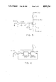
- FIG. 1 is a highly simplified top view of a compartment advanced out of the housing of the device along with the mechanism that drives it.
- FIG. 2 is a highly simplified top view of the compartment inside the housing of the device along with the mechanism that drives it,
- FIG. 3 is a simple circuit for processing the electromagnetic force
- FIG. 4 is a block diagram illustrating the motor, processing circuit, and controls.
- FIGS. 1 and 2 are schematic illustrations of a slide-out compartment 7 that can be advanced out of the housing 6 of a compact-disk player to accommodate a compact disk and introduced back into the housing, along with the mechanisms that govern these motions and that consist of a motor 1, a belt 4 and a rack 3 and pinion 2.
- Compartment 7 is designed such that, when it is in either position, even in the snapped-in position wherein a spring F engages a nose 5, a slight pressure P applied against its front surface will move it over a short distance W, which can be only 2 to 3 mm for example, causing it to rotate the rotor of motor 1 through the intermediary of the aforesaid drive mechanisms.
- This operation generates an electromagnetic force that is recognized as a switching signal by an electronic circuit and forwarded to controls.
- the controls which can be a microcomputer for example, respond by generating an operating voltage with a specific polarity for a specific period of time.
- the correct rotation of motor 1 can be conventionally derived from the sequence of "engage” and " disengage” commands.
- FIG. 2 illustrates a simple processing circuit with a transistor 15 with its collector connected through a resistor 16 to a +5-V connection and its emitter through another resistor 14 to a -5-V connection.
- a third resistor 13 provides negative bias, which is unnecessary when the electromagnetic force is powerful enough.
- the electromagnetic force from motor 1 is supplied to the base through a normally closed switch 10 and a resistor 11, elevated to a conventional TTL (5V) level by the processing circuit, and released at the collector output terminal.
- FIG. 4 shows motor 1, switch 10, processing circuit 17, microprocessor 18, and the connections necessary to operate the device.
- Switch 10 is opened by microcomputer 18 only when the latter receives a switching pulse from processing circuit 17, and supplies motor voltage until it opens a limit switch 19 connected to its + input terminal, interrupting the voltage to motor 1 as soon as the desired compartment motion is complete.
Landscapes
- Feeding And Guiding Record Carriers (AREA)
- Drawers Of Furniture (AREA)
- Vending Machines For Individual Products (AREA)
- Platform Screen Doors And Railroad Systems (AREA)
- Sheets, Magazines, And Separation Thereof (AREA)
- Transmission Devices (AREA)
- Circuits Of Receivers In General (AREA)
- Vehicle Body Suspensions (AREA)
- Preliminary Treatment Of Fibers (AREA)
- Feeding Of Articles To Conveyors (AREA)
Applications Claiming Priority (2)
| Application Number | Priority Date | Filing Date | Title |
|---|---|---|---|
| DE19873702887 DE3702887A1 (de) | 1987-01-31 | 1987-01-31 | Geraet mit einer automatischen einzugsvorrichtung |
| DE3702887 | 1987-01-31 |
Publications (1)
| Publication Number | Publication Date |
|---|---|
| US4809254A true US4809254A (en) | 1989-02-28 |
Family
ID=6319938
Family Applications (1)
| Application Number | Title | Priority Date | Filing Date |
|---|---|---|---|
| US07/142,456 Expired - Lifetime US4809254A (en) | 1987-01-31 | 1988-01-07 | Device with an automatic retraction mechanism |
Country Status (8)
| Country | Link |
|---|---|
| US (1) | US4809254A (ko) |
| EP (1) | EP0279059B1 (ko) |
| JP (1) | JP2569102B2 (ko) |
| KR (1) | KR910002064B1 (ko) |
| AT (1) | ATE64227T1 (ko) |
| DE (2) | DE3702887A1 (ko) |
| ES (1) | ES2023653B3 (ko) |
| HK (1) | HK25796A (ko) |
Cited By (6)
| Publication number | Priority date | Publication date | Assignee | Title |
|---|---|---|---|---|
| US5164934A (en) * | 1989-12-20 | 1992-11-17 | Pioneer Electronic Corporation | Tray loading apparatus for disc players |
| US5574711A (en) * | 1993-11-12 | 1996-11-12 | Nakamichi Corporation | Device for driving trays in disk players |
| GB2328781A (en) * | 1997-09-01 | 1999-03-03 | Linn Prod Ltd | Push-sensitive compact disc transport mechanism. |
| DE19738628A1 (de) * | 1997-09-04 | 1999-03-11 | Thomson Brandt Gmbh | Verfahren zum Bedienen eines Geräts zum Lesen und/oder Beschreiben auswechselbarer Informationsträger |
| US20030122459A1 (en) * | 2001-12-27 | 2003-07-03 | Edgar Huber | Movable portion of an article of furniture |
| EP1596386A2 (en) * | 2004-05-12 | 2005-11-16 | Funai Electric Co., Ltd. | Tray drive |
Families Citing this family (5)
| Publication number | Priority date | Publication date | Assignee | Title |
|---|---|---|---|---|
| GB9213600D0 (en) * | 1992-06-26 | 1992-08-12 | Rolls Royce Motor Cars | Apparatus for retracting a retractable protrusion |
| JP2002500802A (ja) * | 1998-03-27 | 2002-01-08 | コーニンクレッカ フィリップス エレクトロニクス エヌ ヴィ | 駆動モータによって活性化できるアクティブモードを有する記録と再生との双方又はいずれか一方の装置 |
| JP3619986B2 (ja) * | 2000-04-17 | 2005-02-16 | オリオン電機株式会社 | 記録再生装置 |
| KR20070078171A (ko) | 2006-01-26 | 2007-07-31 | 삼성전자주식회사 | 신호대 잡음비에 의한 억제 정도 조절을 이용한 잡음 제거장치 및 그 방법 |
| DE202006012087U1 (de) * | 2006-08-04 | 2007-12-20 | Grass Gmbh | Vorrichtung zum Bewegen eines ersten Möbelteils relativ zu einem zweiten Möbelteil und Möbel |
Citations (4)
| Publication number | Priority date | Publication date | Assignee | Title |
|---|---|---|---|---|
| US2478346A (en) * | 1943-08-04 | 1949-08-09 | Hartford Nat Bank & Trust Co | Starting device for non-self-starting phonograph motors |
| US4697259A (en) * | 1983-10-11 | 1987-09-29 | Nippon Gakki Seizo Kabushiki Kaisha | Disc automatically setting device of a disc player |
| US4723185A (en) * | 1983-09-17 | 1988-02-02 | Canon Kabushiki Kaisha | Recording and/or reproducing apparatus |
| US4730296A (en) * | 1984-10-03 | 1988-03-08 | Nippon Gakki Seizo Kabushiki Kaisha | Loading device in a disc playback device |
Family Cites Families (8)
| Publication number | Priority date | Publication date | Assignee | Title |
|---|---|---|---|---|
| BE773819A (fr) * | 1971-10-12 | 1972-01-31 | Staar Sa | Appareil d'enregistrement ou de reproduction de bandes magnetiques emmagasinees en cassettes. |
| US4434444A (en) * | 1980-02-08 | 1984-02-28 | Olympus Optical Company Ltd. | Tape cassette loading device for cassette tape recorder |
| JPS5778673A (en) * | 1980-10-02 | 1982-05-17 | Toshiba Corp | Automatic loading device |
| US4564930A (en) * | 1982-07-20 | 1986-01-14 | Pioneer Electronic Corporation | Disc carrying system |
| US4499407A (en) * | 1983-01-21 | 1985-02-12 | Applied Motion Products, Inc. | Brushless DC motor assembly with improved stator pole |
| DE3505339A1 (de) * | 1984-02-17 | 1985-08-29 | Pioneer Electronic Corp., Tokio/Tokyo | Wechselmechanismus |
| NL8500594A (nl) * | 1985-03-04 | 1986-10-01 | Philips Nv | Platenspeler met een laadmechanisme voor het laden van een plaat. |
| JPH0528623A (ja) * | 1991-07-25 | 1993-02-05 | Sony Corp | デイスクプレーヤ |
-
1987
- 1987-01-31 DE DE19873702887 patent/DE3702887A1/de not_active Withdrawn
- 1987-12-16 DE DE8787118621T patent/DE3770620D1/de not_active Expired - Lifetime
- 1987-12-16 ES ES87118621T patent/ES2023653B3/es not_active Expired - Lifetime
- 1987-12-16 AT AT87118621T patent/ATE64227T1/de not_active IP Right Cessation
- 1987-12-16 EP EP87118621A patent/EP0279059B1/de not_active Expired - Lifetime
-
1988
- 1988-01-07 US US07/142,456 patent/US4809254A/en not_active Expired - Lifetime
- 1988-01-29 JP JP63017496A patent/JP2569102B2/ja not_active Expired - Lifetime
- 1988-01-30 KR KR8800803A patent/KR910002064B1/ko not_active IP Right Cessation
-
1996
- 1996-02-08 HK HK25796A patent/HK25796A/xx not_active IP Right Cessation
Patent Citations (4)
| Publication number | Priority date | Publication date | Assignee | Title |
|---|---|---|---|---|
| US2478346A (en) * | 1943-08-04 | 1949-08-09 | Hartford Nat Bank & Trust Co | Starting device for non-self-starting phonograph motors |
| US4723185A (en) * | 1983-09-17 | 1988-02-02 | Canon Kabushiki Kaisha | Recording and/or reproducing apparatus |
| US4697259A (en) * | 1983-10-11 | 1987-09-29 | Nippon Gakki Seizo Kabushiki Kaisha | Disc automatically setting device of a disc player |
| US4730296A (en) * | 1984-10-03 | 1988-03-08 | Nippon Gakki Seizo Kabushiki Kaisha | Loading device in a disc playback device |
Cited By (9)
| Publication number | Priority date | Publication date | Assignee | Title |
|---|---|---|---|---|
| US5164934A (en) * | 1989-12-20 | 1992-11-17 | Pioneer Electronic Corporation | Tray loading apparatus for disc players |
| US5574711A (en) * | 1993-11-12 | 1996-11-12 | Nakamichi Corporation | Device for driving trays in disk players |
| GB2328781A (en) * | 1997-09-01 | 1999-03-03 | Linn Prod Ltd | Push-sensitive compact disc transport mechanism. |
| DE19738628A1 (de) * | 1997-09-04 | 1999-03-11 | Thomson Brandt Gmbh | Verfahren zum Bedienen eines Geräts zum Lesen und/oder Beschreiben auswechselbarer Informationsträger |
| US20030122459A1 (en) * | 2001-12-27 | 2003-07-03 | Edgar Huber | Movable portion of an article of furniture |
| US7159957B2 (en) | 2001-12-27 | 2007-01-09 | Julius Blum Gesellschaft M.B.H. | Actuator for a movable portion of an article of furniture |
| EP1596386A2 (en) * | 2004-05-12 | 2005-11-16 | Funai Electric Co., Ltd. | Tray drive |
| US20050259533A1 (en) * | 2004-05-12 | 2005-11-24 | Funai Electric Co., Ltd. | Tray drive |
| EP1596386A3 (en) * | 2004-05-12 | 2008-08-06 | Funai Electric Co., Ltd. | Tray drive |
Also Published As
| Publication number | Publication date |
|---|---|
| KR880009354A (ko) | 1988-09-14 |
| JP2569102B2 (ja) | 1997-01-08 |
| ATE64227T1 (de) | 1991-06-15 |
| DE3702887A1 (de) | 1988-08-11 |
| KR910002064B1 (en) | 1991-04-01 |
| EP0279059A1 (de) | 1988-08-24 |
| EP0279059B1 (de) | 1991-06-05 |
| DE3770620D1 (de) | 1991-07-11 |
| ES2023653B3 (es) | 1992-02-01 |
| HK25796A (en) | 1996-02-16 |
| JPS63201943A (ja) | 1988-08-22 |
Similar Documents
| Publication | Publication Date | Title |
|---|---|---|
| US4809254A (en) | Device with an automatic retraction mechanism | |
| US3485500A (en) | Tape cartridge locking and ejector mechanism | |
| US5574711A (en) | Device for driving trays in disk players | |
| US5260925A (en) | Disc-record player having automatic loading and unloading features | |
| US4573088A (en) | Control device for the tape deck of a magnetic tape cassette apparatus | |
| HU203422B (en) | Charging and ejecting mechanism for cd-players | |
| US2670210A (en) | Phonograph apparatus | |
| US4220339A (en) | Caddy-actuated declutching mechanism for video disc player | |
| JPS6113298B2 (ko) | ||
| US6330216B1 (en) | Recording medium transfer apparatus | |
| US4358841A (en) | Video disc player having stylus protecting apparatus | |
| US6789260B2 (en) | Disk drive apparatus | |
| US4390978A (en) | Carriage translating mechanism for video disc player | |
| US7939776B2 (en) | Switch mechanism and disk device | |
| US5121268A (en) | Apparatus for recording and/or reproducing information with a lid for protecting the recording medium and a recording medium loading/ejecting mechanism | |
| GB2093628A (en) | Disc record player | |
| US4408315A (en) | Video disc player having stylus cleaning apparatus | |
| KR970001667B1 (ko) | 트레이 구동장치 | |
| US4635148A (en) | Cassette-receiving door device for cassette tape recorder | |
| JPS60119652A (ja) | 情報再生又は情報記録装置 | |
| US4493070A (en) | Video disc player having carriage drive mechanism | |
| US4466028A (en) | Device for reversing a recording medium for use with a recording and reproducing apparatus | |
| JPH09139002A (ja) | ローディング・イジェクト装置 | |
| JP2508031Y2 (ja) | テ―プカセット装填装置 | |
| KR930000496Y1 (ko) | 전원 ‘오프’시 플레이 버튼 인출회로 |
Legal Events
| Date | Code | Title | Description |
|---|---|---|---|
| AS | Assignment |
Owner name: DEUTSCHE THOMSON-BRANDT GMBH, D-7730 VILLINGEN-SCH Free format text: ASSIGNMENT OF ASSIGNORS INTEREST.;ASSIGNOR:SCHEFFLER, WILFRIED;REEL/FRAME:004817/0409 Effective date: 19871214 |
|
| STCF | Information on status: patent grant |
Free format text: PATENTED CASE |
|
| CC | Certificate of correction | ||
| FEPP | Fee payment procedure |
Free format text: PAYOR NUMBER ASSIGNED (ORIGINAL EVENT CODE: ASPN); ENTITY STATUS OF PATENT OWNER: LARGE ENTITY |
|
| FPAY | Fee payment |
Year of fee payment: 4 |
|
| FEPP | Fee payment procedure |
Free format text: PAYER NUMBER DE-ASSIGNED (ORIGINAL EVENT CODE: RMPN); ENTITY STATUS OF PATENT OWNER: LARGE ENTITY Free format text: PAYOR NUMBER ASSIGNED (ORIGINAL EVENT CODE: ASPN); ENTITY STATUS OF PATENT OWNER: LARGE ENTITY |
|
| FPAY | Fee payment |
Year of fee payment: 8 |
|
| FPAY | Fee payment |
Year of fee payment: 12 |