US479217A - Hiesh kaplan - Google Patents
Hiesh kaplan Download PDFInfo
- Publication number
- US479217A US479217A US479217DA US479217A US 479217 A US479217 A US 479217A US 479217D A US479217D A US 479217DA US 479217 A US479217 A US 479217A
- Authority
- US
- United States
- Prior art keywords
- valve
- kaplan
- spring
- hiesh
- lamp
- Prior art date
- Legal status (The legal status is an assumption and is not a legal conclusion. Google has not performed a legal analysis and makes no representation as to the accuracy of the status listed.)
- Expired - Lifetime
Links
- 238000010276 construction Methods 0.000 description 1
- 238000005192 partition Methods 0.000 description 1
- 238000009877 rendering Methods 0.000 description 1
- 235000002020 sage Nutrition 0.000 description 1
- 210000003813 thumb Anatomy 0.000 description 1
Images
Classifications
-
- B—PERFORMING OPERATIONS; TRANSPORTING
- B65—CONVEYING; PACKING; STORING; HANDLING THIN OR FILAMENTARY MATERIAL
- B65D—CONTAINERS FOR STORAGE OR TRANSPORT OF ARTICLES OR MATERIALS, e.g. BAGS, BARRELS, BOTTLES, BOXES, CANS, CARTONS, CRATES, DRUMS, JARS, TANKS, HOPPERS, FORWARDING CONTAINERS; ACCESSORIES, CLOSURES, OR FITTINGS THEREFOR; PACKAGING ELEMENTS; PACKAGES
- B65D1/00—Rigid or semi-rigid containers having bodies formed in one piece, e.g. by casting metallic material, by moulding plastics, by blowing vitreous material, by throwing ceramic material, by moulding pulped fibrous material or by deep-drawing operations performed on sheet material
-
- Y—GENERAL TAGGING OF NEW TECHNOLOGICAL DEVELOPMENTS; GENERAL TAGGING OF CROSS-SECTIONAL TECHNOLOGIES SPANNING OVER SEVERAL SECTIONS OF THE IPC; TECHNICAL SUBJECTS COVERED BY FORMER USPC CROSS-REFERENCE ART COLLECTIONS [XRACs] AND DIGESTS
- Y02—TECHNOLOGIES OR APPLICATIONS FOR MITIGATION OR ADAPTATION AGAINST CLIMATE CHANGE
- Y02E—REDUCTION OF GREENHOUSE GAS [GHG] EMISSIONS, RELATED TO ENERGY GENERATION, TRANSMISSION OR DISTRIBUTION
- Y02E60/00—Enabling technologies; Technologies with a potential or indirect contribution to GHG emissions mitigation
- Y02E60/10—Energy storage using batteries
-
- Y—GENERAL TAGGING OF NEW TECHNOLOGICAL DEVELOPMENTS; GENERAL TAGGING OF CROSS-SECTIONAL TECHNOLOGIES SPANNING OVER SEVERAL SECTIONS OF THE IPC; TECHNICAL SUBJECTS COVERED BY FORMER USPC CROSS-REFERENCE ART COLLECTIONS [XRACs] AND DIGESTS
- Y10—TECHNICAL SUBJECTS COVERED BY FORMER USPC
- Y10T—TECHNICAL SUBJECTS COVERED BY FORMER US CLASSIFICATION
- Y10T137/00—Fluid handling
- Y10T137/8593—Systems
- Y10T137/86292—System with plural openings, one a gas vent or access opening
- Y10T137/8634—With vented outlet
Definitions
- My invention has relation to improvements in safety oil-cans, and more particularly to that class intended for family use, wherein the contents of the can can only be discharged when properly operated; and to these ends the novelty consists in the construction, combination, and arrangement of the several parts of the same, as will be hereinafter more fully described, and particularly pointed out in the claim.
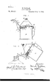
- Figure 1 is a vertical section of my improved safety oil-can with the valve closed
- Fig. 2 is a similar View with the valve open and the can shown in the position required to fill a lamp.
- A represents the can proper, and it is provided with an air-tight cap B, by means of which the can is filled.
- O is the spout, and it is provided with a horizontal longitudinal partition D, extending from the mouth of the spout to a point near the base of the same, and it divides the spout into an oil-channel E and an air-pas-v sage F.
- G is a conical valve-seat, in which seats the correspondingly-shaped valve H, and said valve is secured to the arm I of the rod K, which passes through a tube L, extending through and secured fiush with the outside of the walls of the body of said can.
- the free end of the rod K terminates in a pushbutton M, by means of which said rod and valve are operated, and the face of the valve has secured to it a guide-stem N, which slides freely in a guide-bracket O, secured to and depending from the tube L, and upon said stem and between the valve-seat and the collar P, rigidly secured to the stem, is a spiral spring S, the tension of which serves to keep the valve H tightly closed.
- T is a thumb-spring, one end of which is secured to the top of the handle U, and the free end t of said spring is bent downward to form a stop, against which the button M rests to hold the valve H open inthe act of filling the lamp, as shown in Fig. 2.
- Fig. 1 the can is shown in its normal position, with the valve H closed.
- the spout is inserted in the orifice in the lamp and the button M pushed in until it is caught and held by the spring T, as is clearly shown in Fig. 2.
- the oilin the lamp has risen to the mouth of the spout O, the supply of air is cut off, and consequently no more oil flows from the can.
- the spring T is now pressed down with the thumb, which releases the button M, and the spring S closes the valve and the can is restored to its normal position.
- a lamp can be expeditiously and safely filled without any danger of overflowing or spilling any of the oil, and when the can is not in use should it become accidentally upset the valve prevents the escape of the contents, thus rendering it a very desirable utensil for household use, especially among children and unaware or careless servants.
Landscapes
- Engineering & Computer Science (AREA)
- Ceramic Engineering (AREA)
- Mechanical Engineering (AREA)
- Containers And Packaging Bodies Having A Special Means To Remove Contents (AREA)
Description
(Nomodvel') H. KAPLAN.
SAFETY OIL CAN. No. 479,217. Patented July 19, 1892.
m: uuams'wzrzns 2 Pnufoirmo WASHINGTON, o. c.
UNITED STATES PATENT OFFICE.
HIRSH KAPLAN, OF NEW YORK, N. Y.
SAFETY OIL-CAN.
SPECIFICATION forming part of Letters Patent No. 479,217, dated July 19, 1892.
Application filed April 15, 1892. Serial No. 429,080. (No model.)
To all whom it may concern:
Be it known that I, HIRSH KAPLAN, a citi zen of the United States, residing at New York, in the county of New York and State of New York, have invented certain new and useful Improvements in Safety Oil-Cans; and I do declare the following to be a full, clear, and exact description of the invention, such as will enable others skilled in the art to which it appertains to make and use the same, reference being had to the-accompanying drawings, and to the letters of reference marked thereon, which form part a of this specification.
My invention has relation to improvements in safety oil-cans, and more particularly to that class intended for family use, wherein the contents of the can can only be discharged when properly operated; and to these ends the novelty consists in the construction, combination, and arrangement of the several parts of the same, as will be hereinafter more fully described, and particularly pointed out in the claim.
In the accompanying drawings the same letters of referenceindicate the same parts of the invention.
Figure 1 is a vertical section of my improved safety oil-can with the valve closed, and Fig. 2 is a similar View with the valve open and the can shown in the position required to fill a lamp.
A represents the can proper, and it is provided with an air-tight cap B, by means of which the can is filled.
O is the spout, and it is provided with a horizontal longitudinal partition D, extending from the mouth of the spout to a point near the base of the same, and it divides the spout into an oil-channel E and an air-pas-v sage F.
G is a conical valve-seat, in which seats the correspondingly-shaped valve H, and said valve is secured to the arm I of the rod K, which passes through a tube L, extending through and secured fiush with the outside of the walls of the body of said can. The free end of the rod K terminates in a pushbutton M, by means of which said rod and valve are operated, and the face of the valve has secured to it a guide-stem N, which slides freely in a guide-bracket O, secured to and depending from the tube L, and upon said stem and between the valve-seat and the collar P, rigidly secured to the stem, is a spiral spring S, the tension of which serves to keep the valve H tightly closed.
T is a thumb-spring, one end of which is secured to the top of the handle U, and the free end t of said spring is bent downward to form a stop, against which the button M rests to hold the valve H open inthe act of filling the lamp, as shown in Fig. 2.
In Fig. 1 the can is shown in its normal position, with the valve H closed. When it is desired to fill a lamp or other vessel, the spout is inserted in the orifice in the lamp and the button M pushed in until it is caught and held by the spring T, as is clearly shown in Fig. 2. This holds the valve open and the oil flows out of the can into the lamp through the channel E, and air is supplied to the can through the passage F. When the oilin the lamp has risen to the mouth of the spout O, the supply of air is cut off, and consequently no more oil flows from the can. The spring T is now pressed down with the thumb, which releases the button M, and the spring S closes the valve and the can is restored to its normal position. It will thus be seen that a lamp can be expeditiously and safely filled without any danger of overflowing or spilling any of the oil, and when the can is not in use should it become accidentally upset the valve prevents the escape of the contents, thus rendering it a very desirable utensil for household use, especially among children and ignorant or careless servants.
Having thus fully described my invention, what I claim as new and useful, and desire to secure by Letters Patent of the United States, 1s-
The combination, with the can A, having cap B, double spout O, and thumb-spring T, of the valve H, secured to one end of the rod K, the other end of which terminates in a push-button M, which is adapted to be engaged by the said thumb-spring T, substantially as shown and described.
In testimony whereof I affix my signature in presence of two witnesses.
[-IIRSH KAPLAN.
lVitnesses:
S. H. SHLAMBURG, H. J. ENNIS.
Publications (1)
| Publication Number | Publication Date |
|---|---|
| US479217A true US479217A (en) | 1892-07-19 |
Family
ID=2548071
Family Applications (1)
| Application Number | Title | Priority Date | Filing Date |
|---|---|---|---|
| US479217D Expired - Lifetime US479217A (en) | Hiesh kaplan |
Country Status (1)
| Country | Link |
|---|---|
| US (1) | US479217A (en) |
Cited By (5)
| Publication number | Priority date | Publication date | Assignee | Title |
|---|---|---|---|---|
| US4746036A (en) * | 1987-02-02 | 1988-05-24 | Messner Marvin M | Gasoline container |
| US4834270A (en) * | 1987-02-02 | 1989-05-30 | Messner Marvin M | Gasoline container |
| US5918854A (en) * | 1996-04-23 | 1999-07-06 | The Coca-Cola Company | Pop-up valve closure for a container |
| US20140061254A1 (en) * | 2012-08-28 | 2014-03-06 | Conrad H. Wilkins | Valved fluid transport container |
| US20160145012A1 (en) * | 2014-11-26 | 2016-05-26 | Des-Case Corporation | Oil Dispensing Lid |
-
0
- US US479217D patent/US479217A/en not_active Expired - Lifetime
Cited By (7)
| Publication number | Priority date | Publication date | Assignee | Title |
|---|---|---|---|---|
| US4746036A (en) * | 1987-02-02 | 1988-05-24 | Messner Marvin M | Gasoline container |
| US4834270A (en) * | 1987-02-02 | 1989-05-30 | Messner Marvin M | Gasoline container |
| US5918854A (en) * | 1996-04-23 | 1999-07-06 | The Coca-Cola Company | Pop-up valve closure for a container |
| US20140061254A1 (en) * | 2012-08-28 | 2014-03-06 | Conrad H. Wilkins | Valved fluid transport container |
| US8950637B2 (en) * | 2012-08-28 | 2015-02-10 | Conrad H. Wilkins | Valved fluid transport container |
| US20160145012A1 (en) * | 2014-11-26 | 2016-05-26 | Des-Case Corporation | Oil Dispensing Lid |
| US10308405B2 (en) * | 2014-11-26 | 2019-06-04 | Des-Case Corporation | Oil dispensing lid |
Similar Documents
| Publication | Publication Date | Title |
|---|---|---|
| US479217A (en) | Hiesh kaplan | |
| US788683A (en) | Dispensing-bottle. | |
| US178818A (en) | Improvement in smelling and perfume bottles | |
| US193381A (en) | Improvement in bottles for liquid blacking | |
| US302565A (en) | Lewis s | |
| US442638A (en) | John a | |
| US1813131A (en) | Dispensing receptacle | |
| US943400A (en) | Funnel. | |
| US324547A (en) | Albeet feeygang | |
| US474172A (en) | Hirsch kaplan | |
| US635855A (en) | Oil-can. | |
| US293468A (en) | Oil-can | |
| US365130A (en) | Oil-can | |
| US547976A (en) | Feed for receptacles | |
| US537970A (en) | Bottle-lock | |
| US356432A (en) | Automatic can-stopper | |
| US361909A (en) | Automatic can-stopper | |
| US649337A (en) | Oil-can. | |
| US1124977A (en) | Non-refillable bottle. | |
| US1071175A (en) | Flask. | |
| US502881A (en) | Funnel | |
| US451974A (en) | Island | |
| US1114589A (en) | Non-refillable bottle. | |
| US551069A (en) | John l | |
| US544617A (en) | Automatic bottle-stopper |