US4745708A - Apparatus for securing a closure - Google Patents
Apparatus for securing a closure Download PDFInfo
- Publication number
- US4745708A US4745708A US06/934,592 US93459286A US4745708A US 4745708 A US4745708 A US 4745708A US 93459286 A US93459286 A US 93459286A US 4745708 A US4745708 A US 4745708A
- Authority
- US
- United States
- Prior art keywords
- door
- hook
- wedge
- cam surface
- end frame
- Prior art date
- Legal status (The legal status is an assumption and is not a legal conclusion. Google has not performed a legal analysis and makes no representation as to the accuracy of the status listed.)
- Expired - Fee Related
Links
- 238000007789 sealing Methods 0.000 claims abstract description 10
- 230000007246 mechanism Effects 0.000 description 10
- 230000009471 action Effects 0.000 description 6
- 238000006073 displacement reaction Methods 0.000 description 6
- 125000006850 spacer group Chemical group 0.000 description 5
- 238000010276 construction Methods 0.000 description 4
- 238000005452 bending Methods 0.000 description 3
- 230000001954 sterilising effect Effects 0.000 description 3
- 238000004659 sterilization and disinfection Methods 0.000 description 3
- 230000005540 biological transmission Effects 0.000 description 1
- 230000008859 change Effects 0.000 description 1
- 238000009434 installation Methods 0.000 description 1
Images


Classifications
-
- E—FIXED CONSTRUCTIONS
- E05—LOCKS; KEYS; WINDOW OR DOOR FITTINGS; SAFES
- E05B—LOCKS; ACCESSORIES THEREFOR; HANDCUFFS
- E05B63/00—Locks or fastenings with special structural characteristics
- E05B63/24—Arrangements in which the fastening members which engage one another are mounted respectively on the wing and the frame and are both movable, e.g. for release by moving either of them
- E05B63/242—Auxiliary bolts on the frame, actuated by bolts on the wing, or vice versa
-
- E—FIXED CONSTRUCTIONS
- E05—LOCKS; KEYS; WINDOW OR DOOR FITTINGS; SAFES
- E05C—BOLTS OR FASTENING DEVICES FOR WINGS, SPECIALLY FOR DOORS OR WINDOWS
- E05C9/00—Arrangements of simultaneously actuated bolts or other securing devices at well-separated positions on the same wing
- E05C9/10—Actuating mechanisms for bars
- E05C9/14—Actuating mechanisms for bars with pins engaging slots
-
- E—FIXED CONSTRUCTIONS
- E05—LOCKS; KEYS; WINDOW OR DOOR FITTINGS; SAFES
- E05B—LOCKS; ACCESSORIES THEREFOR; HANDCUFFS
- E05B47/00—Operating or controlling locks or other fastening devices by electric or magnetic means
- E05B47/0001—Operating or controlling locks or other fastening devices by electric or magnetic means with electric actuators; Constructional features thereof
- E05B2047/0014—Constructional features of actuators or power transmissions therefor
- E05B2047/0018—Details of actuator transmissions
- E05B2047/0023—Nuts or nut-like elements moving along a driven threaded axle
-
- E—FIXED CONSTRUCTIONS
- E05—LOCKS; KEYS; WINDOW OR DOOR FITTINGS; SAFES
- E05B—LOCKS; ACCESSORIES THEREFOR; HANDCUFFS
- E05B47/00—Operating or controlling locks or other fastening devices by electric or magnetic means
- E05B47/0001—Operating or controlling locks or other fastening devices by electric or magnetic means with electric actuators; Constructional features thereof
- E05B2047/0014—Constructional features of actuators or power transmissions therefor
- E05B2047/0018—Details of actuator transmissions
- E05B2047/0024—Cams
- E05B2047/0025—Cams in the form of grooves
-
- E—FIXED CONSTRUCTIONS
- E05—LOCKS; KEYS; WINDOW OR DOOR FITTINGS; SAFES
- E05B—LOCKS; ACCESSORIES THEREFOR; HANDCUFFS
- E05B47/00—Operating or controlling locks or other fastening devices by electric or magnetic means
- E05B47/0001—Operating or controlling locks or other fastening devices by electric or magnetic means with electric actuators; Constructional features thereof
- E05B47/0012—Operating or controlling locks or other fastening devices by electric or magnetic means with electric actuators; Constructional features thereof with rotary electromotors
-
- E—FIXED CONSTRUCTIONS
- E05—LOCKS; KEYS; WINDOW OR DOOR FITTINGS; SAFES
- E05C—BOLTS OR FASTENING DEVICES FOR WINGS, SPECIALLY FOR DOORS OR WINDOWS
- E05C9/00—Arrangements of simultaneously actuated bolts or other securing devices at well-separated positions on the same wing
- E05C9/06—Arrangements of simultaneously actuated bolts or other securing devices at well-separated positions on the same wing with three or more sliding bars
-
- Y—GENERAL TAGGING OF NEW TECHNOLOGICAL DEVELOPMENTS; GENERAL TAGGING OF CROSS-SECTIONAL TECHNOLOGIES SPANNING OVER SEVERAL SECTIONS OF THE IPC; TECHNICAL SUBJECTS COVERED BY FORMER USPC CROSS-REFERENCE ART COLLECTIONS [XRACs] AND DIGESTS
- Y10—TECHNICAL SUBJECTS COVERED BY FORMER USPC
- Y10T—TECHNICAL SUBJECTS COVERED BY FORMER US CLASSIFICATION
- Y10T292/00—Closure fasteners
- Y10T292/08—Bolts
- Y10T292/0801—Multiple
- Y10T292/0848—Swinging
- Y10T292/0849—Operating means
- Y10T292/0859—Push or pull rod
Definitions
- the present invention relates to door sealing mechanisms and, in particular, to a device for securely locking and sealing a door of a pressure vessel.
- a door In various applications, a door must be securely fastened to a door frame. In those applications where a door is provided for a pressure vessel, the door must be secured to various points on the door frame of the pressure vessel to assure a balanced loading of the frame by the force of the pressure to allow complete door sealing. For example, in a sterilization apparatus in which the sterilization chamber is pressurized, a suitable door fastening mechanism must be provided to assure uniform door loading to guarantee complete door sealing during chamber pressurization.
- retaining hooks or notched hook bars are provided on both sides of the door frame which are engaged by bars mounted for horizontal sliding movement on the door.
- the hooks extend inwardly over the door so that the bars may be laterally moved into engagement under the hooks to provide backing support for the bars and, hence, the door, against the pressure within the chamber.
- the door is typically mounted for vertical movement between one elevation in which the door may be opened or is in facing relation but not sealed to the end frame and another lower elevation in which the door is in a position sufficient to engage the hooks or hook bars.
- the subject invention is directed toward an improved means for securing a door of a pressurizable chamber which overcomes, among others, the above-discussed problems and is effective to secure the door without requiring its undue lifting and the costs associated with the mechanisms for doing so.
- an apparatus for securing a door of a chamber to the end frame thereof is provided with a series of clevises on either side thereof.
- the clevises are each provided with a pin on which there is pivotally mounted a swing hook.
- Each swing hook has a first cam surface in proximity to the end frame and a hook surface formed on the reverse side of the swing hook.
- the door is supported on the end frame for swinging movement by means of two or more hinges.
- a slide plate is mounted on the outside of the door for vertical sliding movement powered by a screw which is connected to the slide plate by means of a nut mounted on the slide plate.
- the slide plate is provided with symmetrical cam slots formed therein.
- Vertical longitudinal bars are mounted on the outside of the door for horizontal sliding movement and include rollers mounted on the outer faces thereof. Such rollers are provided to engage the cam slots in the slide plate such that the vertical movement of the slide plate causes the horizontal displacement of the longitudinal bars.
- the door is also provided with a series of horizontal wedge bars which are connected to the longitudinal bars for horizontal sliding movement relative to the door corresponding to the horizontal movement of the longitudinal bars.
- the wedge bars are each provided with a cam surface which may engage the corresponding swing hook.
- a plurality of latch hooks is provided on the outer surface of the door corresponding to each of the wedge bars.
- Each of the latch hooks includes a radiused outer surface which may be engaged by the first cam surface of a corresponding swing hook.
- the operation of the instant invention is effective to cause the door to be moved from one position in which it is facing the end frame but not secured thereto to another position in which the door is moved toward the end frame in order that the seal provided around the perimeter of the inner door face is in sealing relation with the end frame.
- the raising and lowering of the slide plate causes the horizontal displacement of the longitudinal bars and, hence, the wedge bars.
- Such movement of the wedge bars causes the cam surfaces of the wedge bars to contact the first cam surfaces of the swing hooks to cause the swing hooks to rotate.
- each of the cam surfaces thereof rides further along the first cam surface of the corresponding swing hook thereby rotating it and causing its hook surface to engage the latch surface of the latch hook.
- the present invention provides solutions to the aforementioned problems associated with previous door securing means.
- the instant device provides a mechanically expedient door securing means which does not necessitate the excessive lifting of the door, the problems of the prior art sealing devices are alleviated.
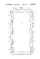
- FIG. 1 is a front elevation view of the end frame of a chamber to which the present invention may be applied;
- FIG. 2 is a front view of a partially assembled door which includes various aspects of the present invention
- FIG. 3 is a front elevation view of a door which embodies the apparatus of the present invention.
- FIG. 4 is a section view of the present invention showing the door securing means in its open position
- FIG. 5 is a section view taken along line 5--5 in FIG. 2;
- FIG. 6 is a section view taken along line 6--6 in FIG. 2;
- FIG. 7 is a section view taken along line 7--7 in FIG. 2;
- FIG. 8 is a section view taken along line 8--8 in FIG. 4;
- FIG. 9 is a section view taken along line 9--9 in FIG. 4.
- FIG. 1 the Figures show a door 10 which may be mounted on the vertical end frame 12 of a vessel 14 having a surrounding shell 16.
- a door 10 of a vessel 14 which may comprise a pressure vessel, such as a sterilization unit, in which the chamber 18 is caused to undergo periods of elevated pressure.
- a pressure vessel such as a sterilization unit
- the door latching mechanism disclosed herein may be employed in an environment in which a door must be secured to a door frame.
- an end frame 12 of the vessel 14 which is perpendicular to the chamber 18.
- a seal 19 is provided about the inner circumference of door 12.
- a plurality of clevises 20 are provided symmetrically on the opposing lateral sides of end frame 12.
- the clevises 20 are each provided with a pin 22 secured thereto.
- Pivotally mounted on each pin 22 is a swing hook 24 which includes a first curved cam surface 26 provided on the side of swing hook 24 closest to end frame 12 and a hook portion 28.
- the hook portions 28 are each provided with an inner curved hook surface 30, the radius of curvature of which is not taken about pin 22.
- the swing hooks 24 are each normally biased into the open position indicated in FIG. 4, in which the hook portion 28 is not in facing relation to end frame 12, by means of coil springs 32 mounted on pin 22 between such and swing hook 24.
- Hinge blocks 34 are provided on end frame 12 to support door 10.
- the hinge blocks are each provided with pins 36 over which pass loosely fitting hinges 38 which are secured to one of the sides of door 10. As such, door 10 may be moved between an open position in which access to chamber 18 is permitted and a confronting position in which door 10 is in facing relation to end frame 12 but not sealed thereto and a sealed position in which door 10 seals chamber 18.
- the door 10 includes a vertical door plate 40 which supports certain of the remainder of the structure of door 10.
- Door 10 is provided with latereal stiffening channels 42 which comprise "U"-shaped channels configured to provide stiffening structure to door 10 to resist the pressure imposed within chamber 18.
- Vertical longitudinal bars 43 are provided on the opposing lateral sides of the outer surface of door 10 and are supported on channels 42 by means of rollers 44 which are supported by slots 45 in channels 42. As such, longitudinal bars 43 may move horizontally relative to door 10 on channels 42.
- a vertical slide plate 46 is provided to slide vertically along the outer surface of door 10 as described hereinbelow.
- the slide plate 46 includes cam slots 48 which are primarily vertical in orientation but which are also provided with a horizontal component of displacement.
- Slide plate 46 is supported on longitudinal bars 43 by means of rollers 49 mounted thereon which engage cam slots 48.
- a nut 50 is provided on the upper central portion of slide plate 46 and is screwedly engaged by a vertical screw 52 which also serves to support door 10. The movement of slide plate 46 is caused by the rotation of screw 52 which causes nut 50 to travel on screw 52.
- slide plate 46 is vertically displaced relative to rollers 49 and longitudinal bars 43.
- the rotation of screw 52 may be manually powered or, more preferably, is mechanically powered by means of an electric motor 54 which, through a transmission 56, drives a gear 58.
- the rotational force of gear 58 is transmitted to screw 52 by means of a chain 60 passing between gear 58 and a second gear 62 which is attached to the end of screw 52.
- the rotation of motor 54 powers screw 52 and, hence, the vertical displacement of slide plate 46.
- slide plate 52 when slide plate 52 is vertically displaced, the position of rollers 49 in cam slots 48 will vary. Such variation causes longitudinal bars 43 to move horizontally relative to stiffening channels 42.
- latch hooks 76 are also attached to the outer surfaces of each of the channels 42.
- Latch hooks 76 are provided with laterally extending hooks 78 having an outer curved latch surface 80 of a radius similar to that of the hook surfaces 30 of swing hooks 24.
- the distance between inner hook surface 30 and end frame 12 when swing hook 24 is in its closed position as shown in FIG. 5 is slightly less than that from latch surface 80 to end frame 12 when door 12 is in its end frame confronting position.
- the engagement of latch surface 80 of hook 78 by hook surface 30 is the mechanism by which door 10 is secured to end frame 12.
- securing means by which swing hook 24 is caused to engage latch 78 is generally indicated herein by reference numeral 82.
- securing means 82 actually may take three separate forms, namely, 82A, 82B and 82C which are essentially equivalent in terms of their function to secure door 10 to end frame 12, but which differ depending on the additional functions they perform.
- the securing means 82 which is of the simplest construction is securing means 82A.
- Securing means 82A includes a spacer block 84 which passes through slot 85 in a stiffening channel 42 and which is fastened to the inside surface of longitudinal bar 43 by means of screws 86.
- spacer block 84 extends into the interior of the appropriate stiffening channel 42.
- Attached to the inner surface of spacer block 84 also by means of bolts 86 is a horizontal wedge bar.
- wedge bars 88A, 88B and 88C will be defined as those associated with securing means 82A, 82B and 82C, respectively.
- Wedge bar 88A comprises a bar-like member having a roller 90A provided on the lateral end thereof closest to the center of door 10 and a cam surface 92 provided on its outer lateral end.
- cam surfaces 92A, 92B and 92C will refer to those which are provided on the faces of wedge bars 88A, 88B and 88C, respectively, which are remote from door plate 40. It will be appreciated that as a longitudinal bar 43 is moved horizontally by the movement of slide plate 46, a wedge bar 88A attached thereto will also be horizontally displaced. When the longitudinal bars 43 are displaced outwardly, the wedge bar 88A is moved toward swing hook 24.
- securing means 82B includes the rollers 44 on which the longitudinal bars 43 are mounted.
- screws 94 are provided intermediate longitudinal bar 43 and wedge bar 88B.
- Rollers 44 are mounted on screws 94 between longitudinal bar 43 and a spacer block 96 mounted on wedge bar 88B.
- the rollers 44 support the longitudinal bars 43 on slots 45 in stiffening channels 42.
- Wedge bars 88B also include a roller 90B and a cam surface 92B.
- the operation of securing means 82B is similar to that of securing means 82A. When longitudinal bars 43 are displaced horizontally outward, they are supported by rollers 44 in slots 45 of stiffening channels 42.
- each of the longitudinal bars 43 causes wedge bar 88B to move outward thereby moving cam surface 92B toward its corresponding swing hook 24.
- the continued movement of wedge bar 88B causes cam surface 92B to cause swing hook 24 to rotate such that hook surface 30 increasingly engages latch surface 80.
- the engagement of hook surface 30 with latch surface 80 causes latch 78 to be displaced toward end frame 12 thereby drawing door 10 toward end frame 12 and compresses the seal 19.
- swing hook 24 is rotated to its open position as indicated in FIG. 4.
- Securing means 82C incorporates functions in addition to those of the other securing means 82.
- Securing means 82C includes a wedge bar 88C which is also attached to longitudinal bar 43 by means of screws 86 passing through a spacer block 84 and into wedge bar 88C.
- a roller 90C is provided on the inboard end of wedge bar 88C.
- Wedge bar 80C is also provided with a cam surface 92C which functions like cam surfaces 92A and 92B to cause swing hook 24 to engage latch hook 76 and be released therefrom.
- wedge bar 88C is also provided with a first recessed area 100 on the inner side thereof facing door plate 40, which recessed area 100 is operatively adjacent a cam surface 102 also formed on the inner side of wedge bar 88C opposite to cam surface 92C.
- a second recessed area 104 is formed on the outer surface of wedge bar 92C facing away from door plate 40 and is operatively adjacent to a second cam surface 105.
- a roller 106 is attached to the underside of channel 42 in facing relation to wedge bar 92C.
- a roller block 108 is supported on each of the lateral sides of door plate 40 on pins 109 such that horizontal movement of roller block 108 toward and away from wedge bar 88C is permitted.
- Roller block 108 is provided with a pair of rollers 110 which are in facing relation to and may ride on first recessed area 100 and first cam surface 102 of wedge bar 92C.
- a second roller 112 is also provided on roller block 108 which faces and may ride on end frame 12. As such, when wedge bar 92C is retracted into channel 42, rollers 110 are seated in first recessed area 100 and second roller 104 is seated in recessed area 104 and roller 112 is not in engagement with end frame 12.
- rollers 110 When wedge bar 88C is extended toward swing hook 24, rollers 110 are caused to ride on cam surface 102 to the elevated area thereof. This action causes wedge block 108 and, hence, roller 112 to be extended relative to end frame 12 thereby causing door 10 to be displaced therefrom by an amount sufficient to break the seal at seal 19 to allow door 12 to be opened.
- the action of rollers 110 on cam surface 102 is opposed by roller 106 which rides on cam surface 105 when wedge bar 92C is retracted so that wedge bar 92C is not subject to excessive bending stresses.
- the slide plate 46 In the operation of the present invention, in order for the door 10 to be opened relative to end frame 12, the slide plate 46 must be moved to its maximum upper position by means of the action of motor 54 driving screw 52 which is coupled to nut 50.
- the motor 54 rotates screw 52 in one direction thereby causing nut 50 and slide plate 46 to be lowered.
- the continued lowering of slide plate 46 relative to door 40 causes the longitudinal bars 43 to be moved horizontally outward toward the outer edges of door 10 and toward the swing hooks 24.
- an additional feature of the present invention serves to provide security to the door 10 retaining mechanism provided herein.
- door 10 When pressure is applied to the chamber and, hence, door 10 tends to force door 10 and latch hook 76 outward from end frame 12.
- latch hook 76 causes latch surface 80 to attempt to rotate swing hook 24 to its open position.
- first cam surface 26 of swing hook 24 to transmit the rotational force to cam surface 92C of wedge bar 88C and press wedge bar 88C against the clevis 20. This action further prevents the retraction of wedge bar 88C and any opening of door 10 under conditions of pressure.
- first roller 110 of roller block 108 is caused to ride on raised cam surface 102 which causes a force directed toward end frame 12 to be provided on roller block 108 and, hence, roller 112 thereby causing it to press against end frame 12 to break the seal formed by seal 19.
- the force created by roller 110 on surface 102 is resisted by roller 106 riding on cam surface 105 to prevent bending of wedge bar 88C.
- the roller 90C serves to prevent the inner end of wedge bar 88C from contacting the inner surface of door plate 40.
Landscapes
- Engineering & Computer Science (AREA)
- Physics & Mathematics (AREA)
- Electromagnetism (AREA)
- Structural Engineering (AREA)
- Mechanical Engineering (AREA)
- Pressure Vessels And Lids Thereof (AREA)
- Specific Sealing Or Ventilating Devices For Doors And Windows (AREA)
Priority Applications (2)
| Application Number | Priority Date | Filing Date | Title |
|---|---|---|---|
| US06/934,592 US4745708A (en) | 1986-11-25 | 1986-11-25 | Apparatus for securing a closure |
| JP62297316A JPS63210462A (ja) | 1986-11-25 | 1987-11-25 | 扉の固定装置 |
Applications Claiming Priority (1)
| Application Number | Priority Date | Filing Date | Title |
|---|---|---|---|
| US06/934,592 US4745708A (en) | 1986-11-25 | 1986-11-25 | Apparatus for securing a closure |
Publications (1)
| Publication Number | Publication Date |
|---|---|
| US4745708A true US4745708A (en) | 1988-05-24 |
Family
ID=25465772
Family Applications (1)
| Application Number | Title | Priority Date | Filing Date |
|---|---|---|---|
| US06/934,592 Expired - Fee Related US4745708A (en) | 1986-11-25 | 1986-11-25 | Apparatus for securing a closure |
Country Status (2)
| Country | Link |
|---|---|
| US (1) | US4745708A (ja) |
| JP (1) | JPS63210462A (ja) |
Cited By (10)
| Publication number | Priority date | Publication date | Assignee | Title |
|---|---|---|---|---|
| US4922660A (en) * | 1988-11-16 | 1990-05-08 | Crown Forest Industries Limited | Plywood veneer dryer door |
| US5704167A (en) * | 1996-04-09 | 1998-01-06 | Martin Engineering Company | Removable access door with multiple pivot axes |
| WO1998020222A1 (en) * | 1996-11-06 | 1998-05-14 | Christian Guillemette | Security device for a dead bolt lock |
| WO2001055543A1 (de) * | 2000-01-24 | 2001-08-02 | Niewöhner, Bruno | Sektionalhub- oder falttor |
| FR2806749A1 (fr) * | 2000-03-21 | 2001-09-28 | Michel Guy Rene Gelin | Dispositif de renforcement de porte |
| US6391258B1 (en) * | 1999-10-07 | 2002-05-21 | Barnstead/Thermolyne Corporation | Pressure vessel having electromechanical latching mechanism |
| US20040265167A1 (en) * | 2003-06-30 | 2004-12-30 | Todd Morrison | Sterilization vacuum chamber door closure |
| US20040267132A1 (en) * | 2003-06-30 | 2004-12-30 | Ethicon, Inc. | Ultrasonic radial focused transducer for pulmonary vein ablation |
| US20060075950A1 (en) * | 2002-02-04 | 2006-04-13 | Dasilva Robert A | Hatch or door system for securing and sealing openings in marine vessels |
| US20060175026A1 (en) * | 2004-09-29 | 2006-08-10 | Edgar Griebel | Sectional gate with escape door |
Families Citing this family (2)
| Publication number | Priority date | Publication date | Assignee | Title |
|---|---|---|---|---|
| JPH02136855U (ja) * | 1989-04-21 | 1990-11-15 | ||
| JP4635775B2 (ja) * | 2005-08-05 | 2011-02-23 | 三浦工業株式会社 | 扉閉鎖構造とそれを用いた密閉容器 |
Citations (2)
| Publication number | Priority date | Publication date | Assignee | Title |
|---|---|---|---|---|
| US4020594A (en) * | 1975-08-06 | 1977-05-03 | Evans Products Company | Leverless door mechanism |
| US4095640A (en) * | 1977-02-02 | 1978-06-20 | Beckerer Frank S Jr | Boat window |
-
1986
- 1986-11-25 US US06/934,592 patent/US4745708A/en not_active Expired - Fee Related
-
1987
- 1987-11-25 JP JP62297316A patent/JPS63210462A/ja active Pending
Patent Citations (2)
| Publication number | Priority date | Publication date | Assignee | Title |
|---|---|---|---|---|
| US4020594A (en) * | 1975-08-06 | 1977-05-03 | Evans Products Company | Leverless door mechanism |
| US4095640A (en) * | 1977-02-02 | 1978-06-20 | Beckerer Frank S Jr | Boat window |
Cited By (17)
| Publication number | Priority date | Publication date | Assignee | Title |
|---|---|---|---|---|
| US4922660A (en) * | 1988-11-16 | 1990-05-08 | Crown Forest Industries Limited | Plywood veneer dryer door |
| US5704167A (en) * | 1996-04-09 | 1998-01-06 | Martin Engineering Company | Removable access door with multiple pivot axes |
| WO1998020222A1 (en) * | 1996-11-06 | 1998-05-14 | Christian Guillemette | Security device for a dead bolt lock |
| AU732226B2 (en) * | 1996-11-06 | 2001-04-12 | Christian Guillemette | Security device for a dead bolt lock |
| US6391258B1 (en) * | 1999-10-07 | 2002-05-21 | Barnstead/Thermolyne Corporation | Pressure vessel having electromechanical latching mechanism |
| US7201206B2 (en) | 2000-01-24 | 2007-04-10 | Niewöhner Industrie GmbH | Sectional lifting door or folding door |
| WO2001055543A1 (de) * | 2000-01-24 | 2001-08-02 | Niewöhner, Bruno | Sektionalhub- oder falttor |
| US20030141023A1 (en) * | 2000-01-24 | 2003-07-31 | Edgar Griebel | Sectional lifting door or folding door |
| CZ299004B6 (cs) * | 2000-01-24 | 2008-04-02 | Sekcní zdvižná nebo skládací vrata | |
| FR2806749A1 (fr) * | 2000-03-21 | 2001-09-28 | Michel Guy Rene Gelin | Dispositif de renforcement de porte |
| US7213530B2 (en) * | 2002-02-04 | 2007-05-08 | Kazak Composites, Incorporated | Hatch or door system for securing and sealing openings in marine vessels |
| US20060075950A1 (en) * | 2002-02-04 | 2006-04-13 | Dasilva Robert A | Hatch or door system for securing and sealing openings in marine vessels |
| US20040265167A1 (en) * | 2003-06-30 | 2004-12-30 | Todd Morrison | Sterilization vacuum chamber door closure |
| US20050132533A1 (en) * | 2003-06-30 | 2005-06-23 | Nguyen Nick N. | Sterilization vacuum chamber door closure |
| US20040267132A1 (en) * | 2003-06-30 | 2004-12-30 | Ethicon, Inc. | Ultrasonic radial focused transducer for pulmonary vein ablation |
| US20060175026A1 (en) * | 2004-09-29 | 2006-08-10 | Edgar Griebel | Sectional gate with escape door |
| US8307875B2 (en) * | 2004-09-29 | 2012-11-13 | Niewohner Industrie GmbH & Co., KG | Sectional gate with escape door |
Also Published As
| Publication number | Publication date |
|---|---|
| JPS63210462A (ja) | 1988-09-01 |
Similar Documents
| Publication | Publication Date | Title |
|---|---|---|
| US4745708A (en) | Apparatus for securing a closure | |
| US3802125A (en) | Three track sliding aircraft door | |
| US4899420A (en) | Hinge system | |
| US4372603A (en) | Double pivot door for cargo vehicles | |
| CA2310436A1 (en) | Combined sliding and pivot window assembly | |
| CA2096488A1 (en) | Mechanism for releasably locking sashes in door- or window frames | |
| US5022691A (en) | Side lock for a roll-up door | |
| US4726145A (en) | Sliding door assembly | |
| ES2014500B3 (es) | Impulsor giratorio para mover puertas giratorias en vehiculos | |
| KR20090018824A (ko) | 화물선 해치용 작동기 메커니즘 | |
| GB1436850A (en) | Window frames | |
| US4913476A (en) | Door latch and release apparatus | |
| SU824889A3 (ru) | Люковое закрытие | |
| US4075787A (en) | Inflatable pouch to seal | |
| CA2150924A1 (en) | One-or two-leaf sliding door, swinging door or pocket door | |
| US2956836A (en) | Door construction for vehicles and the like | |
| US6035674A (en) | Door locking device with several closing rods | |
| US6637347B1 (en) | Anti-spin/anti-drift module for railway car door | |
| US3511593A (en) | Door closing and locking means for autoclaves and the like | |
| US4020594A (en) | Leverless door mechanism | |
| GB2290336A (en) | Door or window security device | |
| US4756123A (en) | Chamber door | |
| NL9301579A (nl) | Schuifdeuraandrijving. | |
| US3797170A (en) | Locking assembly for sliding plug doors | |
| EP0351484A3 (en) | Spring-latch door lock provided with an improved locking system and adapted to be used for inwardly and outwardly opened doors |
Legal Events
| Date | Code | Title | Description |
|---|---|---|---|
| AS | Assignment |
Owner name: AMERICAN STERILIZER COMPANY, A PA CORP Free format text: ASSIGNMENT OF ASSIGNORS INTEREST.;ASSIGNOR:ROCHE, JOHN N.;REEL/FRAME:004650/0582 Effective date: 19861120 Owner name: AMERICAN STERILIZER COMPANY Free format text: ASSIGNMENT OF ASSIGNORS INTEREST;ASSIGNOR:ROCHE, JOHN N.;REEL/FRAME:004650/0582 Effective date: 19861120 |
|
| CC | Certificate of correction | ||
| REMI | Maintenance fee reminder mailed | ||
| REMI | Maintenance fee reminder mailed | ||
| LAPS | Lapse for failure to pay maintenance fees | ||
| FP | Lapsed due to failure to pay maintenance fee |
Effective date: 19920524 |
|
| STCH | Information on status: patent discontinuation |
Free format text: PATENT EXPIRED DUE TO NONPAYMENT OF MAINTENANCE FEES UNDER 37 CFR 1.362 |