US4739621A - Cooling scheme for combustor vane interface - Google Patents
Cooling scheme for combustor vane interface Download PDFInfo
- Publication number
- US4739621A US4739621A US06/659,748 US65974884A US4739621A US 4739621 A US4739621 A US 4739621A US 65974884 A US65974884 A US 65974884A US 4739621 A US4739621 A US 4739621A
- Authority
- US
- United States
- Prior art keywords
- turbine vanes
- turbine
- vanes
- platform
- adjacent
- Prior art date
- Legal status (The legal status is an assumption and is not a legal conclusion. Google has not performed a legal analysis and makes no representation as to the accuracy of the status listed.)
- Expired - Lifetime
Links
Images

Classifications
-
- F—MECHANICAL ENGINEERING; LIGHTING; HEATING; WEAPONS; BLASTING
- F01—MACHINES OR ENGINES IN GENERAL; ENGINE PLANTS IN GENERAL; STEAM ENGINES
- F01D—NON-POSITIVE DISPLACEMENT MACHINES OR ENGINES, e.g. STEAM TURBINES
- F01D9/00—Stators
- F01D9/02—Nozzles; Nozzle boxes; Stator blades; Guide conduits, e.g. individual nozzles
- F01D9/023—Transition ducts between combustor cans and first stage of the turbine in gas-turbine engines; their cooling or sealings
-
- F—MECHANICAL ENGINEERING; LIGHTING; HEATING; WEAPONS; BLASTING
- F23—COMBUSTION APPARATUS; COMBUSTION PROCESSES
- F23R—GENERATING COMBUSTION PRODUCTS OF HIGH PRESSURE OR HIGH VELOCITY, e.g. GAS-TURBINE COMBUSTION CHAMBERS
- F23R3/00—Continuous combustion chambers using liquid or gaseous fuel
- F23R3/02—Continuous combustion chambers using liquid or gaseous fuel characterised by the air-flow or gas-flow configuration
- F23R3/04—Air inlet arrangements
- F23R3/06—Arrangement of apertures along the flame tube
-
- Y—GENERAL TAGGING OF NEW TECHNOLOGICAL DEVELOPMENTS; GENERAL TAGGING OF CROSS-SECTIONAL TECHNOLOGIES SPANNING OVER SEVERAL SECTIONS OF THE IPC; TECHNICAL SUBJECTS COVERED BY FORMER USPC CROSS-REFERENCE ART COLLECTIONS [XRACs] AND DIGESTS
- Y02—TECHNOLOGIES OR APPLICATIONS FOR MITIGATION OR ADAPTATION AGAINST CLIMATE CHANGE
- Y02T—CLIMATE CHANGE MITIGATION TECHNOLOGIES RELATED TO TRANSPORTATION
- Y02T50/00—Aeronautics or air transport
- Y02T50/60—Efficient propulsion technologies, e.g. for aircraft
Definitions
- This invention relates to gas turbine engines and particularly to the combustor and turbine vane assembly.
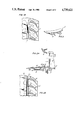
- FIG. 1a is a partial showing of an annular combustor for a twin spool axial flow turbine power plant of the type exemplified by the engine models JT9D, PW2037 and PW4000 manufactured by Pratt & Whitney of United Technologies Corporation, the assignee of this patent application.
- the inner and outer louver liners 10 and 12 are suitably attached to the vane supports 14 and 16 which are ultimately tied to the inner case 18 and outer case 20 all in a well-known manner.
- the inner and outer louver liners are constrained at the discharged end in a toroidally shaped body and define a passageway for leading the engine's working fluid into the space between the vanes 22 (one being shown) to impinge on the turbine blades 24.
- FIG. 1B which is a projected view of FIG. 1A and as shown by the arrows, the cooling air which is introduced from the annular cavity 26 which is fed by the engine's compressor (not shown) is directed toward the critical parts of the vane assembly to assure that these parts withstand the hostile environment.
- the hot spots identified by reference letter A is caused by high temperature, high velocity of the engines working fluid being displaced by the vane's leading edge 30, and consequently, migrating to the vane platforms 32 and 34 and the burner trailing edge 36 (in proximity to the location of the arrows B).
- FIG. 1A is a partial view of a turbine type power plant in section showing the combustor/turbine vane assembly exemplifying the prior art construction.
- FIG. 1B is a partial projected view of the vane and trailing edge of the burner showing the problem of the heretofore construction.
- FIG. 2A is a partial view identical to FIG. 1A but with the invention added.
- FIG. 2B is a partial projected view of FIG. 2A.
- FIG. 3 is an oblique view of the channels located on the trailing edge of the louver liner of FIG. 2A.
- the problem is to assure that the critical components of the gas turbine engine do not become distressed and particularly the area in proximity to the louver trailing edge and the leading edge of the 1st row of vanes ahead of the 1st turbine stage (the area where the temperature of the engine is substantially the hottest).
- FIGS. 1A and 1B showing the identical structure before the incorporation of the invention together with the model engines identified above and incorporated herein by reference.
- louver support member 42 defining a sheath surrounding the louver 40 that is supported by the sheet metal attachment 44 connected to vane platform 32.
- the louver support member 42 and louver 40 define an annular cooling chamber 46 which is fed compressor discharge air from cavity 26 (see FIG. 1A) through apertures 48 (one being shown).
- the trailing edges 43 and 45 of louver 40 and louver support member 42 or sheath respectively are spaced defining an annular open-ended channel.
- the discharge end of sheath 42 is deformed so as to be dimensioned into sinusoidal shaped configuration to define circumferentially spaced open-ended channels 50.
- the open-ended channels 50 are judiciously located relative to the vanes 22 (see FIG. 2b) so that the cooling air which is at a relatively high velocity is directed toward only the region created by the leading edge and platform of the vanes 22.
- this serves to louver the temperature of the boundaries of the hot gas path (fluid working medium) so as to attenuate and even in some instances eliminate the vortices that were induced by the vanes as shown in the prior art design.
- the incorporation of the channels serve to provide high "back side" convective heat transfer coefficients to further cool the trailing edge of the louver liner.
Landscapes
- Engineering & Computer Science (AREA)
- Mechanical Engineering (AREA)
- General Engineering & Computer Science (AREA)
- Chemical & Material Sciences (AREA)
- Combustion & Propulsion (AREA)
- Turbine Rotor Nozzle Sealing (AREA)
Priority Applications (8)
| Application Number | Priority Date | Filing Date | Title |
|---|---|---|---|
| US06/659,748 US4739621A (en) | 1984-10-11 | 1984-10-11 | Cooling scheme for combustor vane interface |
| CA000486033A CA1245869A (fr) | 1984-10-11 | 1985-06-28 | Methode de refroidissement pour l'interface entre les ailettes et le dispositif combustor |
| DE8585630109T DE3566010D1 (en) | 1984-10-11 | 1985-07-11 | Cooling scheme for combustor vane interface |
| DE198585630109T DE178242T1 (de) | 1984-10-11 | 1985-07-11 | Kuehlungskonzept fuer den brennkammer-leitschaufel-uebergang. |
| EP85630109A EP0178242B1 (fr) | 1984-10-11 | 1985-07-11 | Projet de refroidissement pour la transition d'une chambre de combustion aux aubes de guidage |
| IL75780A IL75780A (en) | 1984-10-11 | 1985-07-12 | Cooling scheme for combustor vane interface |
| JP60168448A JPS6196140A (ja) | 1984-10-11 | 1985-07-30 | ガスタ−ビンエンジンの支持構造体 |
| CN85105913.9A CN1003879B (zh) | 1984-10-11 | 1985-08-05 | 燃烧室/定叶片界面冷却方案 |
Applications Claiming Priority (1)
| Application Number | Priority Date | Filing Date | Title |
|---|---|---|---|
| US06/659,748 US4739621A (en) | 1984-10-11 | 1984-10-11 | Cooling scheme for combustor vane interface |
Publications (1)
| Publication Number | Publication Date |
|---|---|
| US4739621A true US4739621A (en) | 1988-04-26 |
Family
ID=24646666
Family Applications (1)
| Application Number | Title | Priority Date | Filing Date |
|---|---|---|---|
| US06/659,748 Expired - Lifetime US4739621A (en) | 1984-10-11 | 1984-10-11 | Cooling scheme for combustor vane interface |
Country Status (7)
| Country | Link |
|---|---|
| US (1) | US4739621A (fr) |
| EP (1) | EP0178242B1 (fr) |
| JP (1) | JPS6196140A (fr) |
| CN (1) | CN1003879B (fr) |
| CA (1) | CA1245869A (fr) |
| DE (2) | DE178242T1 (fr) |
| IL (1) | IL75780A (fr) |
Cited By (15)
| Publication number | Priority date | Publication date | Assignee | Title |
|---|---|---|---|---|
| US5101620A (en) * | 1988-12-28 | 1992-04-07 | Sundstrand Corporation | Annular combustor for a turbine engine without film cooling |
| US5303543A (en) * | 1990-02-08 | 1994-04-19 | Sundstrand Corporation | Annular combustor for a turbine engine with tangential passages sized to provide only combustion air |
| US5394687A (en) * | 1993-12-03 | 1995-03-07 | The United States Of America As Represented By The Department Of Energy | Gas turbine vane cooling system |
| US5398496A (en) * | 1993-03-11 | 1995-03-21 | Rolls-Royce, Plc | Gas turbine engines |
| DE19813779A1 (de) * | 1998-03-27 | 1999-09-30 | Bmw Rolls Royce Gmbh | Anordnung zur Kühlung der Plattformen von Leitschaufeln einer Gasturbine |
| US6276897B1 (en) | 1998-12-05 | 2001-08-21 | Abb Alstom Power (Schweiz) Ag | Cooling in gas turbines |
| WO2004029415A1 (fr) * | 2002-09-26 | 2004-04-08 | Siemens Westinghouse Power Corporation | Dispositif de guidage de fluide de perturbation de vortex thermotolerant |
| WO2004038181A1 (fr) * | 2002-10-23 | 2004-05-06 | Pratt & Whitney Canada Corp. | Procede aerodynamique pour reduire le niveau du bruit dans des turbines a gaz |
| EP1731711A1 (fr) * | 2005-06-10 | 2006-12-13 | Siemens Aktiengesellschaft | Transition de la chambre de combustion à la turbine, écran thermique et aube du distributeur de turbine |
| EP1265030B1 (fr) * | 2001-06-06 | 2008-07-09 | Snecma | Accrochage de chambre de combustion CMC de turbomachine par viroles de liaison souples |
| US20080190114A1 (en) * | 2007-02-08 | 2008-08-14 | Raymond Surace | Gas turbine engine component cooling scheme |
| US20100122538A1 (en) * | 2008-11-20 | 2010-05-20 | Wei Ning | Methods, apparatus and systems concerning the circumferential clocking of turbine airfoils in relation to combustor cans and the flow of cooling air through the turbine hot gas flowpath |
| US20100313571A1 (en) * | 2007-12-29 | 2010-12-16 | Alstom Technology Ltd | Gas turbine |
| CN103184895A (zh) * | 2011-12-30 | 2013-07-03 | 通用电气公司 | 涡轮机转子叶片平台冷却装置 |
| US20160177758A1 (en) * | 2014-04-04 | 2016-06-23 | United Technologies Corporation | Angled rail holes |
Families Citing this family (17)
| Publication number | Priority date | Publication date | Assignee | Title |
|---|---|---|---|---|
| US5083422A (en) * | 1988-03-25 | 1992-01-28 | General Electric Company | Method of breach cooling |
| US4916906A (en) * | 1988-03-25 | 1990-04-17 | General Electric Company | Breach-cooled structure |
| DE9203776U1 (de) * | 1992-03-20 | 1992-05-21 | Schreckling, Kurt, 5090 Leverkusen | Kleingasturbine, insbesondere zum Antrieb von Flugmodellen |
| GB9305010D0 (en) * | 1993-03-11 | 1993-04-28 | Rolls Royce Plc | A cooled turbine nozzle assembly and a method of calculating the diameters of cooling holes for use in such an assembly |
| GB9305012D0 (en) * | 1993-03-11 | 1993-04-28 | Rolls Royce Plc | Sealing structures for gas turbine engines |
| US6419446B1 (en) * | 1999-08-05 | 2002-07-16 | United Technologies Corporation | Apparatus and method for inhibiting radial transfer of core gas flow within a core gas flow path of a gas turbine engine |
| US6969232B2 (en) | 2002-10-23 | 2005-11-29 | United Technologies Corporation | Flow directing device |
| US20100054922A1 (en) * | 2008-09-04 | 2010-03-04 | General Electric Company | Turbine airfoil clocking |
| JP5180807B2 (ja) | 2008-12-24 | 2013-04-10 | 三菱重工業株式会社 | 1段静翼の冷却構造、及びガスタービン |
| US8439626B2 (en) * | 2008-12-29 | 2013-05-14 | General Electric Company | Turbine airfoil clocking |
| JP5479058B2 (ja) | 2009-12-07 | 2014-04-23 | 三菱重工業株式会社 | 燃焼器とタービン部との連通構造、および、ガスタービン |
| CN102146844A (zh) * | 2010-02-10 | 2011-08-10 | 中国科学院工程热物理研究所 | 航空发动机涡轮叶片的零冷气消耗超强度冷却装置 |
| JP5031110B2 (ja) * | 2011-01-21 | 2012-09-19 | 三菱重工業株式会社 | ガスタービン |
| US9157331B2 (en) * | 2011-12-08 | 2015-10-13 | Siemens Aktiengesellschaft | Radial active clearance control for a gas turbine engine |
| JP2012107628A (ja) * | 2012-01-27 | 2012-06-07 | Mitsubishi Heavy Ind Ltd | ガスタービン |
| JP5506834B2 (ja) * | 2012-01-27 | 2014-05-28 | 三菱重工業株式会社 | ガスタービン |
| CN108442985B (zh) * | 2018-04-11 | 2020-10-27 | 西安交通大学 | 一种具有提高静叶通道端壁冷却效率的槽缝冷却结构 |
Citations (6)
| Publication number | Priority date | Publication date | Assignee | Title |
|---|---|---|---|---|
| US3186168A (en) * | 1962-09-11 | 1965-06-01 | Lucas Industries Ltd | Means for supporting the downstream end of a combustion chamber in a gas turbine engine |
| US3307354A (en) * | 1965-10-01 | 1967-03-07 | Gen Electric | Cooling structure for overlapped panels |
| US3527053A (en) * | 1968-12-11 | 1970-09-08 | Gen Electric | Gas turbine engine with improved gas seal |
| US3565545A (en) * | 1969-01-29 | 1971-02-23 | Melvin Bobo | Cooling of turbine rotors in gas turbine engines |
| US3670497A (en) * | 1970-09-02 | 1972-06-20 | United Aircraft Corp | Combustion chamber support |
| US4025226A (en) * | 1975-10-03 | 1977-05-24 | United Technologies Corporation | Air cooled turbine vane |
Family Cites Families (6)
| Publication number | Priority date | Publication date | Assignee | Title |
|---|---|---|---|---|
| US3126705A (en) * | 1956-03-26 | 1964-03-31 | Combustion system | |
| FR1248821A (fr) * | 1960-02-17 | 1960-12-23 | Entwicklungsbau Pirna Veb | Chambre de combustion annulaire pour turbines à gaz, notamment pour avions et turbine équipée de ladite chambre ou d'une chambre similaire |
| DE1199541B (de) * | 1961-12-04 | 1965-08-26 | Jan Jerie Dr Ing | Sammler von Treibgasen fuer das Leitrad von Gasturbinen |
| US3608310A (en) * | 1966-06-27 | 1971-09-28 | Gen Motors Corp | Turbine stator-combustor structure |
| US3965066A (en) * | 1974-03-15 | 1976-06-22 | General Electric Company | Combustor-turbine nozzle interconnection |
| USH903H (en) * | 1982-05-03 | 1991-04-02 | General Electric Company | Cool tip combustor |
-
1984
- 1984-10-11 US US06/659,748 patent/US4739621A/en not_active Expired - Lifetime
-
1985
- 1985-06-28 CA CA000486033A patent/CA1245869A/fr not_active Expired
- 1985-07-11 DE DE198585630109T patent/DE178242T1/de active Pending
- 1985-07-11 EP EP85630109A patent/EP0178242B1/fr not_active Expired
- 1985-07-11 DE DE8585630109T patent/DE3566010D1/de not_active Expired
- 1985-07-12 IL IL75780A patent/IL75780A/xx not_active IP Right Cessation
- 1985-07-30 JP JP60168448A patent/JPS6196140A/ja active Pending
- 1985-08-05 CN CN85105913.9A patent/CN1003879B/zh not_active Expired
Patent Citations (6)
| Publication number | Priority date | Publication date | Assignee | Title |
|---|---|---|---|---|
| US3186168A (en) * | 1962-09-11 | 1965-06-01 | Lucas Industries Ltd | Means for supporting the downstream end of a combustion chamber in a gas turbine engine |
| US3307354A (en) * | 1965-10-01 | 1967-03-07 | Gen Electric | Cooling structure for overlapped panels |
| US3527053A (en) * | 1968-12-11 | 1970-09-08 | Gen Electric | Gas turbine engine with improved gas seal |
| US3565545A (en) * | 1969-01-29 | 1971-02-23 | Melvin Bobo | Cooling of turbine rotors in gas turbine engines |
| US3670497A (en) * | 1970-09-02 | 1972-06-20 | United Aircraft Corp | Combustion chamber support |
| US4025226A (en) * | 1975-10-03 | 1977-05-24 | United Technologies Corporation | Air cooled turbine vane |
Cited By (29)
| Publication number | Priority date | Publication date | Assignee | Title |
|---|---|---|---|---|
| US5101620A (en) * | 1988-12-28 | 1992-04-07 | Sundstrand Corporation | Annular combustor for a turbine engine without film cooling |
| US5303543A (en) * | 1990-02-08 | 1994-04-19 | Sundstrand Corporation | Annular combustor for a turbine engine with tangential passages sized to provide only combustion air |
| US5398496A (en) * | 1993-03-11 | 1995-03-21 | Rolls-Royce, Plc | Gas turbine engines |
| US5394687A (en) * | 1993-12-03 | 1995-03-07 | The United States Of America As Represented By The Department Of Energy | Gas turbine vane cooling system |
| DE19813779B4 (de) * | 1998-03-27 | 2005-04-14 | Rolls-Royce Deutschland Ltd & Co Kg | Anordnung zur Kühlung der Plattformen von Leitschaufeln einer Gasturbine |
| DE19813779A1 (de) * | 1998-03-27 | 1999-09-30 | Bmw Rolls Royce Gmbh | Anordnung zur Kühlung der Plattformen von Leitschaufeln einer Gasturbine |
| US6276897B1 (en) | 1998-12-05 | 2001-08-21 | Abb Alstom Power (Schweiz) Ag | Cooling in gas turbines |
| EP1265030B1 (fr) * | 2001-06-06 | 2008-07-09 | Snecma | Accrochage de chambre de combustion CMC de turbomachine par viroles de liaison souples |
| WO2004029415A1 (fr) * | 2002-09-26 | 2004-04-08 | Siemens Westinghouse Power Corporation | Dispositif de guidage de fluide de perturbation de vortex thermotolerant |
| US6884029B2 (en) | 2002-09-26 | 2005-04-26 | Siemens Westinghouse Power Corporation | Heat-tolerated vortex-disrupting fluid guide component |
| US7234304B2 (en) | 2002-10-23 | 2007-06-26 | Pratt & Whitney Canada Corp | Aerodynamic trip to improve acoustic transmission loss and reduce noise level for gas turbine engine |
| US20070227119A1 (en) * | 2002-10-23 | 2007-10-04 | Pratt & Whitney Canada Corp. | HPT aerodynamic trip to improve acoustic transmission loss and reduce noise level for auxiliary power unit |
| WO2004038181A1 (fr) * | 2002-10-23 | 2004-05-06 | Pratt & Whitney Canada Corp. | Procede aerodynamique pour reduire le niveau du bruit dans des turbines a gaz |
| US7533534B2 (en) | 2002-10-23 | 2009-05-19 | Pratt & Whitney Canada Corp. | HPT aerodynamic trip to improve acoustic transmission loss and reduce noise level for auxiliary power unit |
| EP1731711A1 (fr) * | 2005-06-10 | 2006-12-13 | Siemens Aktiengesellschaft | Transition de la chambre de combustion à la turbine, écran thermique et aube du distributeur de turbine |
| US20080190114A1 (en) * | 2007-02-08 | 2008-08-14 | Raymond Surace | Gas turbine engine component cooling scheme |
| US8403631B2 (en) | 2007-02-08 | 2013-03-26 | United Technologies Corporation | Gas turbine engine component cooling scheme |
| US8403632B2 (en) | 2007-02-08 | 2013-03-26 | United Technologies Corporation | Gas turbine engine component cooling scheme |
| US7862291B2 (en) | 2007-02-08 | 2011-01-04 | United Technologies Corporation | Gas turbine engine component cooling scheme |
| US20110070097A1 (en) * | 2007-02-08 | 2011-03-24 | Raymond Surace | Gas turbine engine component cooling scheme |
| US20110070082A1 (en) * | 2007-02-08 | 2011-03-24 | Raymond Surace | Gas turbine engine component cooling scheme |
| US20100313571A1 (en) * | 2007-12-29 | 2010-12-16 | Alstom Technology Ltd | Gas turbine |
| US8783044B2 (en) * | 2007-12-29 | 2014-07-22 | Alstom Technology Ltd | Turbine stator nozzle cooling structure |
| US8087253B2 (en) * | 2008-11-20 | 2012-01-03 | General Electric Company | Methods, apparatus and systems concerning the circumferential clocking of turbine airfoils in relation to combustor cans and the flow of cooling air through the turbine hot gas flowpath |
| US20100122538A1 (en) * | 2008-11-20 | 2010-05-20 | Wei Ning | Methods, apparatus and systems concerning the circumferential clocking of turbine airfoils in relation to combustor cans and the flow of cooling air through the turbine hot gas flowpath |
| CN103184895A (zh) * | 2011-12-30 | 2013-07-03 | 通用电气公司 | 涡轮机转子叶片平台冷却装置 |
| CN103184895B (zh) * | 2011-12-30 | 2016-03-16 | 通用电气公司 | 涡轮机转子叶片平台冷却装置 |
| US20160177758A1 (en) * | 2014-04-04 | 2016-06-23 | United Technologies Corporation | Angled rail holes |
| US9752447B2 (en) * | 2014-04-04 | 2017-09-05 | United Technologies Corporation | Angled rail holes |
Also Published As
| Publication number | Publication date |
|---|---|
| IL75780A (en) | 1991-04-15 |
| CA1245869A (fr) | 1988-12-06 |
| CN1003879B (zh) | 1989-04-12 |
| DE3566010D1 (en) | 1988-12-08 |
| JPS6196140A (ja) | 1986-05-14 |
| CN85105913A (zh) | 1986-08-06 |
| EP0178242A1 (fr) | 1986-04-16 |
| IL75780A0 (en) | 1985-11-29 |
| EP0178242B1 (fr) | 1988-11-02 |
| DE178242T1 (de) | 1986-10-16 |
Similar Documents
| Publication | Publication Date | Title |
|---|---|---|
| US4739621A (en) | Cooling scheme for combustor vane interface | |
| US4566851A (en) | First stage turbine vane support structure | |
| US4303371A (en) | Shroud support with impingement baffle | |
| US10408073B2 (en) | Cooled CMC wall contouring | |
| US5201846A (en) | Low-pressure turbine heat shield | |
| US4126405A (en) | Turbine nozzle | |
| US3730640A (en) | Seal ring for gas turbine | |
| US5553999A (en) | Sealable turbine shroud hanger | |
| US7229249B2 (en) | Lightweight annular interturbine duct | |
| US6227798B1 (en) | Turbine nozzle segment band cooling | |
| US3628880A (en) | Vane assembly and temperature control arrangement | |
| US5403156A (en) | Integral meter plate for turbine blade and method | |
| JP3671981B2 (ja) | 曲折した冷却用チャネルを備えたタービンシュラウドセグメント | |
| US8177492B2 (en) | Passage obstruction for improved inlet coolant filling | |
| US9810097B2 (en) | Corrugated mid-turbine frame thermal radiation shield | |
| US7229247B2 (en) | Duct with integrated baffle | |
| EP0187731A1 (fr) | Chemise de chambre de combustion pour une turbine à gaz | |
| JP5156362B2 (ja) | 弓形要素を支持するための冠状レール | |
| US6269628B1 (en) | Apparatus for reducing combustor exit duct cooling | |
| US9303528B2 (en) | Mid-turbine frame thermal radiation shield | |
| US20180328188A1 (en) | Turbine engine airfoil insert | |
| US4627233A (en) | Stator assembly for bounding the working medium flow path of a gas turbine engine | |
| US10774657B2 (en) | Baffle assembly for gas turbine engine components | |
| US4525997A (en) | Stator assembly for bounding the flow path of a gas turbine engine | |
| GB2054046A (en) | Cooling turbine rotors |
Legal Events
| Date | Code | Title | Description |
|---|---|---|---|
| AS | Assignment |
Owner name: UNITED TECHNOLOGIES CORPORATION HARTFORD, CT A COR Free format text: ASSIGNMENT OF ASSIGNORS INTEREST.;ASSIGNORS:PETTENGILL, JASON S.;THACKRAH, JOHN S.;SULLIVAN, DENNIS J.;AND OTHERS;REEL/FRAME:004321/0672 Effective date: 19841010 |
|
| STCF | Information on status: patent grant |
Free format text: PATENTED CASE |
|
| FEPP | Fee payment procedure |
Free format text: PAYOR NUMBER ASSIGNED (ORIGINAL EVENT CODE: ASPN); ENTITY STATUS OF PATENT OWNER: LARGE ENTITY |
|
| FPAY | Fee payment |
Year of fee payment: 4 |
|
| FPAY | Fee payment |
Year of fee payment: 8 |
|
| FPAY | Fee payment |
Year of fee payment: 12 |
|
| FEPP | Fee payment procedure |
Free format text: PAYER NUMBER DE-ASSIGNED (ORIGINAL EVENT CODE: RMPN); ENTITY STATUS OF PATENT OWNER: LARGE ENTITY Free format text: PAYOR NUMBER ASSIGNED (ORIGINAL EVENT CODE: ASPN); ENTITY STATUS OF PATENT OWNER: LARGE ENTITY |