US4698228A - Process for extruding dough as used in producing crisp breads - Google Patents
Process for extruding dough as used in producing crisp breads Download PDFInfo
- Publication number
- US4698228A US4698228A US06/798,419 US79841985A US4698228A US 4698228 A US4698228 A US 4698228A US 79841985 A US79841985 A US 79841985A US 4698228 A US4698228 A US 4698228A
- Authority
- US
- United States
- Prior art keywords
- dough
- die
- die slot
- process according
- guide
- Prior art date
- Legal status (The legal status is an assumption and is not a legal conclusion. Google has not performed a legal analysis and makes no representation as to the accuracy of the status listed.)
- Expired - Fee Related
Links
Images


Classifications
-
- A—HUMAN NECESSITIES
- A21—BAKING; EDIBLE DOUGHS
- A21C—MACHINES OR EQUIPMENT FOR MAKING OR PROCESSING DOUGHS; HANDLING BAKED ARTICLES MADE FROM DOUGH
- A21C3/00—Machines or apparatus for shaping batches of dough before subdivision
- A21C3/04—Dough-extruding machines ; Hoppers with moving elements, e.g. rollers or belts as wall elements for drawing the dough
Definitions
- the present invention relates to a process and apparatus for extruding dough, particularly for yeast dough, crisp breads and puffed breakfast cereals.
- the present invention also relates to an extruder die head and more particularly, to dough guides fastened to the die head.
- Extruders currently used for processing yeast dough, crisp breads and puffed breakfast cereals are known and generally comprise one or more feed hoppers which regulate the dry ingredients fed into a twin screw cooker/extruder where water is directly added to the dry ingredients by means of a metering pump.
- U.S. Pat. No. 4,217,083 discloses a complete baking-extrusion-expansion process as shown in FIG. 1, with the extrusion head being the novelty of the invention.
- the extrusion head has a horizontal slot from which dough is extruded onto two pivotable bars. Also, note straps 22 of FIG. 6.
- the texture of the dough is non-uniform.
- the upper surface of the dough is generally more cellular and lighter in color than the bottom surface which contacts the conveyor belt.
- the texture is non-uniform because occluded gases within the dough are much hotter than ambient gases and thus tend to rise.
- the upper horizontal surface of the extruded dough easily allows the gases to evaporate from the dough, thus forming a textured cellular surface.
- the lower horizontal surface of the extruded dough often times does not have the same texture as the upper horizontal surface.
- a cellular texture product results.
- the cellular texture disperses the light impinging on the final product causing a lighter color as compared to a surface which is non-cellular or in which the cellular formation is not uniform. Therefore, the prior art baked dough does not have a consistent uniform color from side to side.
- the present invention provides a process for producing crisp breads having a substantially uniform texture on its major horizontal surfaces.
- the baked products also have a substantially uniform color and appearance.
- the dough is mixed in an extruder and ejected through a die head with at least one vertical die slot.
- the vertically oriented die slot allows the occluded gases to escape more uniformly thus yielding a more uniform texture.
- the die head includes an attached dough guide employed to prevent the dough from expanding excessively, which would result in an oversized product.
- the dough guide is readily adjustable generally independently of the extrusion process. To prevent sticking, the dough guide and die slot can be provided with a non-stick coating such as Teflon®.
- the use of the dough guide of the present invention increases the thermodynamic characteristics of the die itself, allowing the die to operate at a cooler temperature while the extruder maintains the necessary higher temperature to achieve the proper baking of the dough.
- FIG. 1 shows a side view of the extruder with the die head and dough guide.
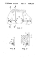
- FIG. 2 shows a front view of the dough guide attached to a die head.
- FIG. 3 shows a bottom view of the dough guide attached to a die head.
- FIG. 4 shows a front view of a different embodiment of the dough guide.
- FIG. 5 shows a bottom view of the dough guide of FIG. 4.
- FIG. 6 shows a front view of another embodiment of the dough guide which is similar to that shown in FIG. 4 but which accommodates a four-slotted die head.
- FIG. 7 shows a front view of a particular embodiment of a support structure for the movable plates.
- FIG. 8 is a section of the support taken along line 8--8 of FIG. 7.
- FIG. 1 shows a typical baking-extrusion-expansion apparatus for the processing of yeast dough, puffed breakfast cereals, and crisp breads.
- the process is accomplished with an extruder 30 which has a communicating hopper 34 at one end of the extruder, with a die head 35 generally at the opposite end of the extruder.
- the extruder can be of the single or twin auger type which are well-known in the art.
- a conventional twinscrew food extrusion system, for example, is the Baker Perkins MPF-50D.
- the pitch of the auger generally decreases from the hopper to the die head so as to gradually increase the pressure on the dough product to be extruded. Extruder pressures generally run in the range of 1000-3000 psi.
- the extruder generally includes a cooker which, for example, could encompass a steam jacket surrounding the extruder. Also, a metering pump for measuring a predetermined amount of water or other liquids is generally associated with the extruder.
- the complete system therefore, can mix the dry goods from the hopper until a uniform composition results. Then the proper amount of water is added to insure uniform hydration of the dough by means of the twin augers. By this time, the dough has been transported to the cooking area of the extruder. This area is surrounded by a steam jacket which cooks the dough as it is transported to the die head. The dough is extruded from the die head where it expands, cools, and is cut. Generally, mixing the dry goods takes about 5-15 minutes.
- Cooking time is generally in the range of 15 seconds to 2 minutes and the temperature is in a range of 160° F. at the beginning zone to about 320° F. at the exit.
- Cooling time before cutting is generally in the range of 3-10 seconds.
- the extrudate should be cooled sufficiently so it doesn't crimp during cutting, yet if too cool it will be brittle and will fracture or crumble during cutting.
- a coating of a non-stick material such as Teflon® can be employed.
- Teflon® coated surfaces allow the surfaces to be cleaned more easily and makes a visible inspection of the die orifices much easier when one attempts to determine the degree of wear of the die. An inspector would know the die orifice is wearing thin if he were to see the Teflon® coating being worn to the point that the underlying metal shows. Also, the use of a Teflon® die yields a product that is more uniform in shape than would be achieved otherwise because the dough does not stick to the Teflon® surface and thus can be extruded in a clean fashion.
- the dough is extruded and guided from the cooker-extruder, it is oriented horizontally by rollers, placed upon an open mesh conveyer belt, and cut by means of a wire cutter, a guillotine cutter, a disc-shaped knife cutter, or by any other suitable means.
- the die head employed at the end of the extruder can be made with one or more vertically oriented rectangular slots.
- bronze or stainless steel is employed in the manufacturing of the die head.
- a bronze die head has better heat transfer characteristics than a stainless steel die head, dissipating heat much more rapidly than the latter. Such a feature helps control the degree of baking of the dough within the cooker-extruder.
- the die slots can be of the replaceable type, thus avoiding replacement of the entire die head when the die slots are worn. Also, varying die slot sizes can be readily obtained by replacement of the die slots.
- a pair of upper guide shafts 81, 81 pass through the upper bores in respective walls 1, 2.
- a pair of lower guide shafts 82, 82 pass through the lower bores in respective walls 1, 2.
- Each upper shaft is welded at one end thereof to a respective one of movable plates 3, 4.
- a plate 41 is retained by nuts 61, 61, and shafts 81, 82, and 8.
- the plate 41 is fixedly attached (as by internal threading, and bias against nuts 61, 61, or welding, or the like) to shafts 81, 82.
- the shaft 8 is not fixed to plate 41, and thus may rotate therein.
- a pair of locknuts 71, 72 is fixed to the shaft 8 so that rotation of shaft 8 by the knob 16 advances the plate 41 either toward or away from wall 1, due to threaded engagement of shaft 8 with the bore in wall 1.
- Shaft 7, in threaded engagement with wall 2 is similar in construction and operation to that described above for shaft 8 and wall 1.
- the screw mechanism attached to plates 3, 4 permits separate adjustment of the location of each of plates 3, 4 by manual rotation of knobs 16, 17 respectively. This allows an operator to position plates 3 and 4 such that size of the extruded product can be critically maintained and controlled.
- the dough guides 1, 2 which are equipped with the shafts 81 and 82 can be calibrated in a manner to indicate the particular thickness desired for the extruded product.
- the knobs 16, 17 would indicate the calibrated thickness, by matching a mark on each of knobs 16, 17 with appropriate reference marks located adjacent the knobs 16, 17.
- FIG. 3 shows an underneath plan view of the dough guide of FIG. 2 further illustrating how the dough guide is attached to the die head 35.
- Die slits 36, 37 are shown in dotted outline in FIG. 3.
- the six screws, each numbered as 10, are shown in FIG. 3.
- Two screws 10 retain each of plates 1, 2, 5 to the plate 6.
- the lower bolt 9 is shown in FIG. 3 in dotted outline received in bore (unnumbered) through the plate 5, the bolt 9 being threaded.
- a threaded bore 12 is also shown in dotted outline, the bolt 9 being threadedly received in the threaded bore 12.
- the bolts 9,9 together fixedly attach the dough guide assembly of the present invention to the die head 35.
- dough is extruded under pressure through the slits 36, 37 in die head 35.
- the dough expands immediately since the ambient pressure is greatly reduced relative to pressure in the extruder 30, and this reduction in pressure causes vaporization of water and expansion of steam, thereby making the product light in weight relative to its enlarged volume.
- the movable plates 3, 4, together with the fixed wall 5, serve to limit expansion of the dough and to control the shape of the subsequent extruded dough product into a plate-like shape of controlled, uniform thickness. Due to a variety of conditions, including internal dough temperature and composition, die slit size, desired product thickness, ambient air pressure, and extruder pressure among other variable conditions, it is desirable to vary the spacing of plates 3, 4 from wall 5, so as to control the product thickness precisely.
- FIGS. 4 and 5 show a further embodiment of the present invention wherein a plate 6 is attached to the die head 35 by screws 99, and further having walls 12, 13, 14, and 15 which are movably positioned with respect to plate 6 and die orifices 36, 37. Walls 12 and 13 are positioned on each side of one of the die slots, while walls 14 and 15 are placed on each side of the other die slot. All the walls are capable of movement with respect to the die slots. This allows the same control of the extruded dough as the dough guide shown in FIGS. 2 and 3. Plates 3, 4 are adjustable as shown in FIGS. 2, 3.
- walls 12 and 15 could be stationary while walls 13 and 14 are movable.
- walls 12 and 15 could be movable while walls 13 and 14 are stationary. If both walls 13 and 14 are stationary, it would be desirable to eliminate one of the walls.
- Any types of supports can be used to adjustably position the plates 12-15, for example the outer plates 1, 2 of FIG. 2 could be used as discussed above to move plates 12, 15, while the plates 13, 14 can be moved by an known support means, or in a preferred embodiment by the guide slot and screw support shown in FIGS. 7-9.
- FIG. 6 shows yet another embodiment of the present invention.
- the dough guide of FIG. 6 is similar to the dough guide of FIGS. 4 and 5 but is for use with a die head that has four die slots 40, 41, 42, and 43.
- the walls 56, 57, 58, 59, 60, 61, 62, and 63 are each movably positioned just as the walls of FIGS. 4 and 5 are, to allow an operator to control the extruded product issuing from the die slots.
- Walls 56, 63 of FIG. 6 may be positionable by use of the mechanism of FIGS. 2 and 3, described hereinabove.
- All of the dough guides shown can be manufactured with a Teflon® coating to prevent sticking of the dough to any of the walls or plates of the dough guide and to allow for easy cleaning.
- the dough guide can be made from metal such as copper, brass, stainless steel or from a hard plastic.
- the dough guide of the present invention comprises walls (such as walls 1, 2, 5 in FIG. 2) which extend perpendicularly from the die head, and hence act as heat fins conducting the heat away from the die head. This yields a dough product which is more uniform in texture.
- FIG. 7 is an enlarged, fragmentary front view of plate 6 of the dough guide shown in FIGS. 2 and 3, and shows a particular embodiment of the support structure for movable plates 13, 14.
- a guide slot member 26 is shown in dotted outline in FIG. 7. The member is fixedly attached to die head 35, as by welding, threaded fasteners, or the like.
- a top key 27 is also shown in dotted outline, this key 27 preventing tilting movement away from wall 6 of plate 13.
- a corresponding key (not shown) is provided on the plate 14.
- Bottom support lugs 19, 21 are securely fixed as by welding or the like to respective movable plates 13, 14, with each lug having a threaded hole therein for positioning by respective screws 22, 23.
- Similar lugs 24, 25 are fixed as by welding or the like to support plate 6, each having a smooth bore therein for passage of positioning screw threaded portions 22, 23, respectively.
- a locknut 98 is fixed to screw 22 on either side of plate 13. Similarily, locknuts 98 are fixed to screw 27. Thus, rotation of heads 18 or 20 causes movement of plates 13 or 14 respectively.
- FIG. 8 is a side sectional view of the support lug 24 and support plate 6, taken along line 8--8 in FIG. 7.
- the lug 24 is similar to lug 25, and is affixed to plate 6 by welding, strong adhesive, threaded fasteners, or the like.
- FIG. 9 is a side sectional view of plate 13 taken along line 9--9 in FIG. 7.
- the guide slot member 26 receives key 27 of plate 13, and prevents tipping of plate 13 away from plate 6 along the top edge.
- Lug 19 is shown formed integrally with the plate 13.
- Plate 14 is similarly constructed. A snug fit between the bores in respective portions 19, 21 and the respective screws 22, 23 prevents any significant rotational play about an axis transverse to the screw axis. This holds true during movement of the plates by operation of the respective screw heads 16, 20, as well.
- any other support structure providing for selectively adjustable movement of plates 13, 14, may be provided.
- the dried products are fed into the extruder by means of hopper 34 and are thoroughly mixed to form a uniform composition.
- the dough is cooked and extruded through the die head 35 causing the dough to expand rapidly as it exits from the die orifice and continues to expand for a few seconds. Since the dough is still hot and flexible, the sudden expansion of the water vapor, as the excess pressure is released, increases the volume by several times. The water than vaporizes from the extruded dough.
- the two vertical sides By vertically extruding the dough the two vertical sides have large surface areas, which allows the occluded gas bubbles near each surface to more easily escape their respective surfaces, thus achieving a more uniformly textured cellular product.
- the bottom and top surfaces In the case of horizontal extrusion, the bottom and top surfaces have a large surface area; however, due to the need to support the bottom surface, uneven escape of occluded gas bubbles occurs on the bottom surface relative to the top surface.
- the left and right surfaces of the extruded product both have large surface areas that are approximately equally exposed to the environment and which therefore tend to allow even escape of occluded gas bubbles from both sides, for an even appearance.
- the coloring of the extruded product is more uniform than that of the prior art because the cellular texture of the extruded product is more uniform.
- the particular fat content of the flour employed in the extruder affects the expansion of the product. In general, as fat content increases, there is a tendency for a reduction in expansion, but the dough is more uniform and the surfaces are smoother, while cell size is smaller and more uniform. Rice flour, which has very little fat content, is easier to expand. Wheat flour which is more commonly employed in dough products, needs higher moisture and a higher temperature (primarily because of the higher fat content) to expand.
- dough improvers can be added to the extruder during the kneading process of the dough in the auger. Improvers such as benzoyl peroxide can be used to bleach flour. Oxidizing agents can be employed to help ferment the dough more uniformly. Enzymes, vitamins, minerals, and mold inhibitors can also be added to the extruder. Such improvers are well-known to those skilled in the art.
- the particular pitch of the twin screw auger employed in the extruder and the particular rotational speed is important in determining the completeness of the mixing of the products, the proper amount of kneading of the dough, and the rate the dough is extruded through the die head.
- the twin screw auger is designed such that the pitch of the blades decreases as one proceeds from the hopper to the die head which arrests the rotary movement imparted to the dough product by the extruder auger and converts it to a linear translational movement toward the die orifice.
- the extruder is a continuous operating process, from time to time a surge of dough exiting from the die head may be encountered.
- the dough guides also help to control such surges that would tend to cause varying degrees of expansion in the product.
- the particular product being extruded can be changed in mid-stream without shutting down the extruder process.
- a switch can be made from extruding a puffed breakfast cereal, for example, to a crisp bread.
- the dough guides of course can be changed without interrupting the extruder process.
Abstract
Description
Claims (7)
Priority Applications (1)
| Application Number | Priority Date | Filing Date | Title |
|---|---|---|---|
| US06/798,419 US4698228A (en) | 1984-03-29 | 1985-11-15 | Process for extruding dough as used in producing crisp breads |
Applications Claiming Priority (2)
| Application Number | Priority Date | Filing Date | Title |
|---|---|---|---|
| US06/594,159 US4659303A (en) | 1984-03-29 | 1984-03-29 | Apparatus for extruding dough as used in producing crisp breads |
| US06/798,419 US4698228A (en) | 1984-03-29 | 1985-11-15 | Process for extruding dough as used in producing crisp breads |
Related Parent Applications (1)
| Application Number | Title | Priority Date | Filing Date |
|---|---|---|---|
| US06/594,159 Division US4659303A (en) | 1984-03-29 | 1984-03-29 | Apparatus for extruding dough as used in producing crisp breads |
Publications (1)
| Publication Number | Publication Date |
|---|---|
| US4698228A true US4698228A (en) | 1987-10-06 |
Family
ID=27081889
Family Applications (1)
| Application Number | Title | Priority Date | Filing Date |
|---|---|---|---|
| US06/798,419 Expired - Fee Related US4698228A (en) | 1984-03-29 | 1985-11-15 | Process for extruding dough as used in producing crisp breads |
Country Status (1)
| Country | Link |
|---|---|
| US (1) | US4698228A (en) |
Cited By (12)
| Publication number | Priority date | Publication date | Assignee | Title |
|---|---|---|---|---|
| US5165949A (en) * | 1989-12-28 | 1992-11-24 | Nestec S.A. | Process for producing extruded food products |
| US5211965A (en) * | 1992-02-25 | 1993-05-18 | Kabushiki Kaisha Takashin | Apparatus for making noodle base |
| US5304055A (en) * | 1991-11-27 | 1994-04-19 | Nabisco, Inc. | Apparatus and methods for the production of three-dimensional food products |
| US5759603A (en) * | 1996-11-15 | 1998-06-02 | Kellogg Company | Process for producing a food product having a distinct phase |
| FR2783403A1 (en) * | 1998-09-21 | 2000-03-24 | Groupe Danone Sa | Kneaded and extruded raw biscuit dough is made in a mixer-extruder with kneading, compression and extrusion zones |
| US6224920B1 (en) * | 1997-03-17 | 2001-05-01 | Vaasanmylly Oy | Process for the manufacture of dry baked products |
| US6291002B1 (en) | 2000-01-26 | 2001-09-18 | Asgdhig Goglanian | Method for preparing elongated pita bread |
| US20040037941A1 (en) * | 2000-11-23 | 2004-02-26 | Ole Knudsen | Method of producing snack and breakfast cereal products and a product produced according to this method |
| US6783782B1 (en) | 1998-12-17 | 2004-08-31 | The Pillsbury Company | Grooved freezer-to-oven pizza crust |
| US20050170053A1 (en) * | 2000-06-30 | 2005-08-04 | Schreiber Foods, Inc. | Food slice consisting of two or more food items, and processes for making and packaging same |
| US7883735B2 (en) | 2006-08-07 | 2011-02-08 | Kellogg Company | Apparatus and method for curled extrudate |
| US20140242245A1 (en) * | 2013-02-28 | 2014-08-28 | Frito-Lay North America, Inc. | Shelf-stable baked crisps and method for making same |
Citations (15)
| Publication number | Priority date | Publication date | Assignee | Title |
|---|---|---|---|---|
| DE157722C (en) * | ||||
| US30221A (en) * | 1860-10-02 | John holmes | ||
| US2068220A (en) * | 1933-05-03 | 1937-01-19 | Firm Gebruder Buhler | Machine for producing foodstuffs made of dough |
| US2148003A (en) * | 1937-04-28 | 1939-02-21 | Jacob B Wurtzel | Butter mold |
| US2261977A (en) * | 1940-07-05 | 1941-11-11 | Alexander T Deutsch | Material working machine |
| US2740157A (en) * | 1951-12-07 | 1956-04-03 | Dow Chemical Co | Method and apparatus for shaping plastic foams |
| US3752614A (en) * | 1971-02-02 | 1973-08-14 | Bremertron Kl Corp | Adjustable extrusion head |
| US3897528A (en) * | 1973-11-21 | 1975-07-29 | Dow Chemical Co | Method for the extrusion of thermoplastic foam |
| US3914085A (en) * | 1972-05-22 | 1975-10-21 | Dow Chemical Co | Extrusion apparatus |
| DE2546583A1 (en) * | 1975-10-17 | 1977-04-21 | Dow Chemical Co | Foam plastics extrusion appts - having slot size adjusting members mounted on the die face |
| US4146563A (en) * | 1977-12-20 | 1979-03-27 | The Dow Chemical Company | Method and apparatus for forming thermoplastic foams |
| US4150929A (en) * | 1977-06-22 | 1979-04-24 | B & H Tool Company, Inc. | Ribbon cable extrusion apparatus |
| US4217083A (en) * | 1977-03-16 | 1980-08-12 | Diepal Corporation | Extrusion head |
| US4292019A (en) * | 1980-01-07 | 1981-09-29 | The Dow Chemical Company | Extruded plastic foam shaping apparatus |
| US4361530A (en) * | 1980-05-02 | 1982-11-30 | Anton Heggenstaller | Method of and apparatus for shaping a strand during extrusion |
-
1985
- 1985-11-15 US US06/798,419 patent/US4698228A/en not_active Expired - Fee Related
Patent Citations (16)
| Publication number | Priority date | Publication date | Assignee | Title |
|---|---|---|---|---|
| US30221A (en) * | 1860-10-02 | John holmes | ||
| DE157722C (en) * | ||||
| US2068220A (en) * | 1933-05-03 | 1937-01-19 | Firm Gebruder Buhler | Machine for producing foodstuffs made of dough |
| US2148003A (en) * | 1937-04-28 | 1939-02-21 | Jacob B Wurtzel | Butter mold |
| US2261977A (en) * | 1940-07-05 | 1941-11-11 | Alexander T Deutsch | Material working machine |
| US2740157A (en) * | 1951-12-07 | 1956-04-03 | Dow Chemical Co | Method and apparatus for shaping plastic foams |
| GB788133A (en) * | 1951-12-07 | 1957-12-23 | Dow Chemical Co | Method and apparatus for shaping plastic foams |
| US3752614A (en) * | 1971-02-02 | 1973-08-14 | Bremertron Kl Corp | Adjustable extrusion head |
| US3914085A (en) * | 1972-05-22 | 1975-10-21 | Dow Chemical Co | Extrusion apparatus |
| US3897528A (en) * | 1973-11-21 | 1975-07-29 | Dow Chemical Co | Method for the extrusion of thermoplastic foam |
| DE2546583A1 (en) * | 1975-10-17 | 1977-04-21 | Dow Chemical Co | Foam plastics extrusion appts - having slot size adjusting members mounted on the die face |
| US4217083A (en) * | 1977-03-16 | 1980-08-12 | Diepal Corporation | Extrusion head |
| US4150929A (en) * | 1977-06-22 | 1979-04-24 | B & H Tool Company, Inc. | Ribbon cable extrusion apparatus |
| US4146563A (en) * | 1977-12-20 | 1979-03-27 | The Dow Chemical Company | Method and apparatus for forming thermoplastic foams |
| US4292019A (en) * | 1980-01-07 | 1981-09-29 | The Dow Chemical Company | Extruded plastic foam shaping apparatus |
| US4361530A (en) * | 1980-05-02 | 1982-11-30 | Anton Heggenstaller | Method of and apparatus for shaping a strand during extrusion |
Non-Patent Citations (2)
| Title |
|---|
| "Extruded Crispbread Fast Mover in Europe", Snack Food, Oct., 1982, pp. 28 and 30. |
| Extruded Crispbread Fast Mover in Europe , Snack Food, Oct., 1982, pp. 28 and 30. * |
Cited By (15)
| Publication number | Priority date | Publication date | Assignee | Title |
|---|---|---|---|---|
| US5165949A (en) * | 1989-12-28 | 1992-11-24 | Nestec S.A. | Process for producing extruded food products |
| US5304055A (en) * | 1991-11-27 | 1994-04-19 | Nabisco, Inc. | Apparatus and methods for the production of three-dimensional food products |
| US5435714A (en) * | 1991-11-27 | 1995-07-25 | Nabisco, Inc. | Apparatus for the production of three-dimensional food products |
| US5211965A (en) * | 1992-02-25 | 1993-05-18 | Kabushiki Kaisha Takashin | Apparatus for making noodle base |
| US5759603A (en) * | 1996-11-15 | 1998-06-02 | Kellogg Company | Process for producing a food product having a distinct phase |
| US6224920B1 (en) * | 1997-03-17 | 2001-05-01 | Vaasanmylly Oy | Process for the manufacture of dry baked products |
| WO2000016635A1 (en) * | 1998-09-21 | 2000-03-30 | Lu | Method for making a strip of kneaded and extruded uncooked batter |
| FR2783403A1 (en) * | 1998-09-21 | 2000-03-24 | Groupe Danone Sa | Kneaded and extruded raw biscuit dough is made in a mixer-extruder with kneading, compression and extrusion zones |
| US6783782B1 (en) | 1998-12-17 | 2004-08-31 | The Pillsbury Company | Grooved freezer-to-oven pizza crust |
| US6291002B1 (en) | 2000-01-26 | 2001-09-18 | Asgdhig Goglanian | Method for preparing elongated pita bread |
| US20050170053A1 (en) * | 2000-06-30 | 2005-08-04 | Schreiber Foods, Inc. | Food slice consisting of two or more food items, and processes for making and packaging same |
| US20040037941A1 (en) * | 2000-11-23 | 2004-02-26 | Ole Knudsen | Method of producing snack and breakfast cereal products and a product produced according to this method |
| US7883735B2 (en) | 2006-08-07 | 2011-02-08 | Kellogg Company | Apparatus and method for curled extrudate |
| US9113657B2 (en) | 2006-08-07 | 2015-08-25 | Kellogg Company | Apparatus and method for curled extrudate |
| US20140242245A1 (en) * | 2013-02-28 | 2014-08-28 | Frito-Lay North America, Inc. | Shelf-stable baked crisps and method for making same |
Similar Documents
| Publication | Publication Date | Title |
|---|---|---|
| US4698228A (en) | Process for extruding dough as used in producing crisp breads | |
| US3332781A (en) | Process for making shaped cereals | |
| US4126706A (en) | Process for forming dough ribbon | |
| US5077074A (en) | Preparation of cookie products involving extrusion heating and wire cutting | |
| EP2061329B1 (en) | Edible wafer products produced by extrusion | |
| US8926308B2 (en) | Dough extruders and methods | |
| US7293974B2 (en) | Apparatus for producing a curly puff extrudate | |
| PL175467B1 (en) | Pregeating and extruding machine for thermal processing of biopolymers and method of preheating and extruding biopolymers | |
| CA2268578C (en) | Method and device for the production of paste products | |
| US6432463B1 (en) | Process for producing expandable pellets | |
| CA2386958C (en) | Process for expanded pellet production | |
| US4659303A (en) | Apparatus for extruding dough as used in producing crisp breads | |
| US9924724B2 (en) | Method and apparatus for making cereal flakes | |
| AP194A (en) | Preparation of flakes. | |
| US7264461B2 (en) | Externally adjustable insert for extrusion manifold | |
| CA2333489A1 (en) | Low shear method for making pasta | |
| USRE30221E (en) | Dough sheet spreader | |
| USRE30222E (en) | Dough sheet spreader | |
| RU2223682C2 (en) | Apparatus and method for obtaining of extruded food product | |
| KR960006076Y1 (en) | Extruding machine of confectionery by handling dough | |
| JP3123752B2 (en) | Method and apparatus for producing thin sheets of starch | |
| JPH03123442A (en) | Production of hollow formed body for snack confectionery | |
| JPH0446539B2 (en) | ||
| AU2002348065A1 (en) | Process for producing expandable pellets |
Legal Events
| Date | Code | Title | Description |
|---|---|---|---|
| CC | Certificate of correction | ||
| FEPP | Fee payment procedure |
Free format text: PAYOR NUMBER ASSIGNED (ORIGINAL EVENT CODE: ASPN); ENTITY STATUS OF PATENT OWNER: LARGE ENTITY |
|
| FPAY | Fee payment |
Year of fee payment: 4 |
|
| AS | Assignment |
Owner name: NABISCO, INC., A NJ CORP., NEW JERSEY Free format text: ASSIGNMENT OF ASSIGNORS INTEREST.;ASSIGNOR:NABISCO BRANDS, INC., A DE CORP.;REEL/FRAME:006059/0606 Effective date: 19920323 |
|
| FPAY | Fee payment |
Year of fee payment: 8 |
|
| FEPP | Fee payment procedure |
Free format text: PAYOR NUMBER ASSIGNED (ORIGINAL EVENT CODE: ASPN); ENTITY STATUS OF PATENT OWNER: LARGE ENTITY Free format text: PAYER NUMBER DE-ASSIGNED (ORIGINAL EVENT CODE: RMPN); ENTITY STATUS OF PATENT OWNER: LARGE ENTITY |
|
| AS | Assignment |
Owner name: NABISCO TECHNOLOGY COMPANY, DELAWARE Free format text: ASSIGNMENT OF ASSIGNORS INTEREST;ASSIGNOR:NABISCO, INC.;REEL/FRAME:008579/0766 Effective date: 19970101 |
|
| FEPP | Fee payment procedure |
Free format text: PAYER NUMBER DE-ASSIGNED (ORIGINAL EVENT CODE: RMPN); ENTITY STATUS OF PATENT OWNER: LARGE ENTITY Free format text: PAYOR NUMBER ASSIGNED (ORIGINAL EVENT CODE: ASPN); ENTITY STATUS OF PATENT OWNER: LARGE ENTITY |
|
| REMI | Maintenance fee reminder mailed | ||
| LAPS | Lapse for failure to pay maintenance fees | ||
| FP | Lapsed due to failure to pay maintenance fee |
Effective date: 19991006 |
|
| STCH | Information on status: patent discontinuation |
Free format text: PATENT EXPIRED DUE TO NONPAYMENT OF MAINTENANCE FEES UNDER 37 CFR 1.362 |