US4682953A - Combined arms effectiveness simulation system - Google Patents
Combined arms effectiveness simulation system Download PDFInfo
- Publication number
- US4682953A US4682953A US06/753,668 US75366885A US4682953A US 4682953 A US4682953 A US 4682953A US 75366885 A US75366885 A US 75366885A US 4682953 A US4682953 A US 4682953A
- Authority
- US
- United States
- Prior art keywords
- target area
- ammunition
- response
- remote
- transmitting
- Prior art date
- Legal status (The legal status is an assumption and is not a legal conclusion. Google has not performed a legal analysis and makes no representation as to the accuracy of the status listed.)
- Expired - Lifetime
Links
Images


Classifications
-
- F—MECHANICAL ENGINEERING; LIGHTING; HEATING; WEAPONS; BLASTING
- F41—WEAPONS
- F41G—WEAPON SIGHTS; AIMING
- F41G3/00—Aiming or laying means
- F41G3/26—Teaching or practice apparatus for gun-aiming or gun-laying
-
- F—MECHANICAL ENGINEERING; LIGHTING; HEATING; WEAPONS; BLASTING
- F41—WEAPONS
- F41G—WEAPON SIGHTS; AIMING
- F41G3/00—Aiming or laying means
- F41G3/26—Teaching or practice apparatus for gun-aiming or gun-laying
- F41G3/2616—Teaching or practice apparatus for gun-aiming or gun-laying using a light emitting device
- F41G3/2622—Teaching or practice apparatus for gun-aiming or gun-laying using a light emitting device for simulating the firing of a gun or the trajectory of a projectile
- F41G3/2655—Teaching or practice apparatus for gun-aiming or gun-laying using a light emitting device for simulating the firing of a gun or the trajectory of a projectile in which the light beam is sent from the weapon to the target
-
- G—PHYSICS
- G01—MEASURING; TESTING
- G01S—RADIO DIRECTION-FINDING; RADIO NAVIGATION; DETERMINING DISTANCE OR VELOCITY BY USE OF RADIO WAVES; LOCATING OR PRESENCE-DETECTING BY USE OF THE REFLECTION OR RERADIATION OF RADIO WAVES; ANALOGOUS ARRANGEMENTS USING OTHER WAVES
- G01S5/00—Position-fixing by co-ordinating two or more direction or position line determinations; Position-fixing by co-ordinating two or more distance determinations
- G01S5/02—Position-fixing by co-ordinating two or more direction or position line determinations; Position-fixing by co-ordinating two or more distance determinations using radio waves
- G01S5/10—Position of receiver fixed by co-ordinating a plurality of position lines defined by path-difference measurements, e.g. omega or decca systems
Definitions
- This invention relates generally to remote actuation systems and more particularly, but not by way of limitation, to a system for designating an affected zone within a target area, which system specifically includes a method and an apparatus for simulating the effectiveness of a selected ammunition within a selected actual geographical target area.
- MILES multiple integrated laser engagement system
- a laser apparatus on each weapon is activated to produce a laser beam directed at the point target when the trigger on the weapon is pulled. If the laser beam strikes a sensor on the target, the target's weapon is disabled by a disabling unit carried by the target, thereby immediately indicating that the target has been hit.
- Another proposal relies upon relatively simple technology which is inexpensive, but it provides an unrealistic effect.
- This proposal provides that a foam rubber bullet be launched by a mortar-type device. The bullet is to be detonated in the air to send an acoustic signal which can actuate the presently used MILES sensors carried by the personnel and equipment within the target area.
- both lasers and microwaves can be adversely affected by the environment where the training is to occur, such as by foliage that is found in battles conducted in wooded areas.
- Such a system should be available for all sizes of military units, such as from the platoon through corps; and use by such units should not interfere with their normal operation (e.g., use of the system should not alter the realism with which a battle is simulated).
- Such a system should also be operational in various types of environments where the fire to be replicated can occur (e.g., rain, fog, mountains, forests).
- the present invention overcomes the above-noted and other shortcomings of the prior art by providing a novel and improved remote actuation system specifically adaptable for use in replicating combined arms fire support for use in training military units.
- This system simulates the effectiveness of various types of munitions on various types of targets; in particular, it defines a realistic zone affected by indirect fire and specifies whether objects (i.e., point targets) within the zone have been hit.
- the present invention is interfaced with the MILES system to provide a complete training package therewith.
- the system can be partially constructed with government-furnished equipment, such as currently used military vehicles and radios and the sensors used in the MILES system.
- the system can also be constructed with non-developmental items commercially available.
- the system requires minimum personnel and training to operate, and the system can be used for various sizes of military units without interferring with their normal operations.
- the preferred embodiment of the present invention utilizes radio frequency signals, thereby permitting the system to be used in various types of environments.
- the present invention in its broader aspects will be useful for simulating other types of weaponry, such as chemicals. It is also contemplated that the present invention can be used to test new systems to evaluate their utility before production. Still another contemplated application of the present invention is as a remote actuation system, specifically one which can be interfaced with the global positioning system (GPS).
- GPS global positioning system
- the system of the present invention provides a method of simulating, within a selected target area, the effectiveness of a selected type of ammunition, comprising the steps of transmitting control signals in response to the selected type of ammunition and the selected target area; transmitting, in response to the control signals, a plurality of radio waves across the selected target area; and indicating, in response to the radio waves, what at the selected target area could have been hit by the selected ammunition had it actually been fired at the selected target area. More particularly, this method includes detecting which type of ammunition is selected to be fired; detecting which target is selected to receive the selected ammunition; transmitting to the selected target signals designating the selected ammunition; and identifying at the selected target specific equipment and personnel affected by the selected ammunition.
- the system of the present invention also broadly provides apparatus for performing the aforementioned functions.
- this apparatus includes a portable indicator apparatus for detecting when an object at the target area has been hit by replicated indirect ammunition fire.
- the portable indicator apparatus comprises radio frequency receiver means, attached to the object, for receiving radio frequency actuating signals; decoder means for determining if the radio frequency actuating signals designate that the object has been hit; and means, responsive to the decoder means, for signifying when the object has been hit by the replicated ammunition fire.
- This means for signifying more particularly includes the disabling means of the MILES system carried by each object within the target area, and interface means for interfacing the decoder means with this disabling means.
- the present invention provides a method of electronically defining a realistic geographical zone, within a geographical target area, which is affected by the replicated firing of a selected type of ammunition into the target area.
- This method comprises the steps of placing a plurality of radio frequency transmitters in electronic line-of-sight communication with the target area and actuating at least three of the transmitters to transmit respective radio frequency waves so that the waves cover a common substantially elliptical region within the target area, thereby defining the affected geographical zone.
- the present invention comprises master control means for generating a master control signal specifying an operation to be performed; remote actuator means, movably spaced from the master control means, for generating an actuation signal in response to the master control signal and for communicating with a global positioning system or any other location determination device or method so that the position of the remote actuator means is determinable; and means for performing the operation in response to the actuation signal.
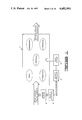
- FIG. 1 is a block diagram of the preferred embodiment of the present invention shown with an exemplary target area and an exemplary ammunition.
- FIG. 2 is an illustration of a specific environment in which the preferred embodiment of the present invention is deployed for replicating indirect fire support.
- FIG. 3 is a block diagram of a master station and three remote actuators operating to define and communicate with an affected geographical zone within a target area.
- FIG. 4 is a functional block diagram of the preferred embodiment of the master station.
- FIG. 5 is a functional block diagram of the preferred embodiment of one of the remote actuators.
- FIG. 6 is a more detailed functional block diagram of the remote actuator shown in FIG. 5.
- FIG. 7 is a functional block diagram of the preferred embodiment of an indicator unit of the present invention.
- FIG. 8 is a more detailed block diagram of the indicator unit shown in FIG. 7.
- FIGS. 9A-9D are diagrams showing different modes of operation of the preferred embodiment of the present invention.
- FIG. 10 shows a time line depicting the interrelationship of the operations of the preferred embodiment of the present invention and the indirect fire whose effectiveness is to be simulated.
- FIGS. 11A-11C show block diagrams of the system timing.
- FIGS. 12A-12B depict the message structure between the master station and remote actuators and between the remote actuators and the indicator units.
- FIG. 13 is a block diagram of a logic circuit implemented in the indicator units.
- FIG. 14 illustrates contemplated enhancements for use with the indicator units and the MILES system.
- FIG. 1 depicts an actual geographical zone 2 across which the indicated point targets comprising eighteen personnel and one truck are dispersed.
- the zone 2 of the target area there is to be replicated the firing of one volley (six rounds) of a selected type of ammunition, specifically shown as a dual purpose improved conventional munition (DPICM).
- DPICM dual purpose improved conventional munition
- the preferred embodiment of the present invention emulates computed munitions effects at the point of impact for fire support munitions. In the preferred embodiment, these effects are based on information from the Joint Munitions Effectiveness Manuals. This emulation is implemented by the master station 4 and remote actuators 6 using radio frequency energy to activate the appliques 8.
- FIG. 2 illustrates the preferred embodiment apparatus deployed in an actual training environment for the purpose of simulating the effect of ammunition fired from an ammunition firing device (e.g., a weapon 12) at a target area 14.
- the master station 4 is located within a wheeled vehicle 16 located near the firing location of the weapon 12.
- the remote actuators 6 are located in wheeled vehicles 18, 20, 22, which are spaced from each other and in between the master station and the target area 14.
- the master station is operated by an individual within the vehicle 16, whereas the remote actuators 18, 20, 22 do not need any operating personnel because they could be fully automatic in responding to the control signals transmitted from the master station 4.
- the operator within the vehicle 16 responds to firing information computed such as by a soldier 24 giving firing commands to the weapon 12.
- FIG. 3 shows that by using at least three remote actuators, radio waves 26 transmitted therefrom sweep across, or cover, (sequentially in the preferred embodiment) a common area to define a more elliptical, rather than a more linear, area which more realistically defines the shape of the coincident zone (or area on the ground) affected by the fire support replicated by the present invention.
- the master station 4 is shown communicating by electromagnetic waves 28 (specifically radio waves in the preferred embodiment) with three remote actuators 30, 32, 34, which represent the remote actuators located within the vehicles 18, 20, 22, respectively.
- the actuator 34 propagates a first actuation signal at a time T, followed by an actuation signal from the remote actuator 32 at time T+1, and a third actuation signal from the actuator 30 at time T+2, which operation will be more particularly described hereinbelow.
- the master station 4 is shown in FIG. 4 as including a radio 36 for receiving data, such as from the soldier 24 at the fire direction center controlling the weapon 12 shown in FIG. 2.
- the radio 36 is any suitable type known to the art, such as of a type presently used by the United States military.
- the data which can be conveyed by voice or by digital signals, includes at least the type of ammunition whose firing from the weapon 12 is to be replicated and the coordinates of the target area 14.
- the radio 36 is connected to a processor 38 through a suitable interface device 40.
- the processor 38 is any suitable computing mechanism, such as a microcomputer of a type manufactured by IBM, Xerox, or other suitable type.
- a data storage device 42 of any suitable type capable of storing the information needed by the processor 38.
- the processor 38 In response to the data input through the radio 36 and the data stored in the data storage 42, the processor 38 generates suitably encoded control signals transmitted as encoded radio waves by a radio 46, which can be the same as or different from the radio 36, connected through an interface 44. Also associated with the processor 38 are a keyboard 48, a display screen 50 and a printer 52 of types as known to the art.
- the elements 36, 38, 40, 42, 44, 46, 48, 50, 52 are mounted within the vehicle 16 to provide a compact, unified, transportable master station. To power these elements, the power from the vehicle 16 can be used. Other suitable power sources, such as commercial power, portable generators, or batteries can be used. Such power is connected to a suitable power distribution unit 54 for driving a power supply 56 providing power signals at the appropriate voltage levels for use by the elements 36-52.
- the elements 36-56 are contemplated to be of types commercially available so that the developmental and maintenance costs of the preferred embodiment of the present invention can be reduced.
- the processor 38 is programmed in any suitable manner for correlating the input data for computing the resulting control signals.
- the control signals are further developed based upon the selected target area known through the data entered via the radio 36.
- the master station provides the planning, coordinating, timing and actuator selecting functions for the overall system of the preferred embodiment of the present invention. Once these functions are performed and the control signals generated, they are transmitted. In the preferred embodiment, transmission is contemplated to be at a power not greater than ten watts and the range of the master station is contemplated to be approximately twenty miles.
- Each remote actuator includes a radio or other radio frequency receiver device 58 of a suitable type known to the art.
- the radio 58 receives the control signals from the master station 4 and provides them to a processor/encoder 60 through an interface 62.
- a standardized timing source 64 allows each processor/encoder 60 to generate an actuating signal, for transmission through a transmitter 66, in response to both the timing signal from the timing source 64 and the timing and target information (type of munition) conveyed to the remote actuator from the master station 4.
- Power for the remote actuator is shown in FIG. 5 as being provided from a generator 68 through a power distribution circuit 70; however, any other suitable type of power can be used to operate the remote actuator. For example, battery or solar power can be used so that the remote actuator can be located in a remote, isolated location and left unattended to automatically operate in response to the control signals from the master station 4.
- FIG. 6 shows that the remote actuator includes a single antenna 72 switchably connectable to either a receiver 74 or the output of a band pass filter 76, which filter forms part of the transmitter 66.
- the receiver 74 is the same type used in the indicator units 8, and it provides its signal to a decoder/timing circuit 78.
- the circuit 78 is controlled by a microprocessor controller 80 to provide a signal to an encoder/timing circuit 82 providing an output which is modulated through a modulator 84 by a radio frequency from a radio frequency source 86.
- the modulated signal is amplified by an amplifier 88 before being output through the band pass filter 76.
- a keyboard 90 and a display 92 are also shown in FIG. 6 as being associated with the microprocessor controller 80.
- the microprocessor controller 80 also includes an interface input 94 for receiving external control signals, such as from the global positioning system which can be utilized to locate the remote actuator as it is moved from place to place.
- the remote actuator is to be small, rugged, highly portable and easy to operate.
- it should be of a size which can fit in a portable carrying case.
- its weight should be relatively light, such as less than fifteen pounds.
- the electronics should be selected so that they can be energized by any suitable power source, such as the battery within the vehicle in which it can be mounted as shown in FIG. 2.
- the transmitter power output should also be kept low, such as to ten watts.
- the carrying case should also accommodate the antenna which can have a magnetic mount or a fixed mount for easy assembly when the remote actuator is positioned at its remote location.
- the preferred embodiment of the remote actuators as well as the indicator units is preferably implemented with the surface acoustic wave technology available through Motorola, Inc. to enhance the operation of the present invention.
- Each unit includes a receiver 96 which provides a signal to a detector/decoder 98.
- the detector/decoder 98 communicates with the MILES disabling unit through an interface 100. These elements are powered by a battery 102.
- FIG. 8 shows a more detailed block diagram of the elements 96, 98, 100.
- the elements shown in FIG. 8 are types as known to the art with the surface acoustic wave (SAW) device 104 and the XN device 106 being members of the Motorola, Inc. 68000 series of chips known to the art.
- SAW surface acoustic wave
- a timing/decoder logic circuit 108 can be switchably, or otherwise, variable by a type code plug 110 to specify the nature of the object with which the indicator is associated.
- the type code plug 110 can be set to define the object as a person or as a truck or any of a plurality of other objects.
- the timing/decoder logic circuit 108 determines for that selected type of object that it has been hit by the replicated ammunition, it generates a hit control signal which in the preferred embodiment causes the MILES disabling unit to disable the weapon of the object. If the object is not hit, a near miss signal is provided so that the object is advised it has been in the affected zone but not hit.
- the disabling unit of the MILES system is of a type as known to the art and will not be more particularly described. Since it is of known type, the interface provided through the timing/decoder logic circuit 108 is of a suitable type for providing the needed inputs to activate the disabling unit of the MILES system carried on each object.
- a 100-megahertz reference clock 111 permits a ten-foot resolution within the affected zone.
- Each indicator unit of the preferred embodiment of the present invention is contemplated to be constructed in a compact size at a weight of less than one pound so that it can be easily carried by personnel without affecting the performance of the personnel during a training exercise. Since there are to be many indicator units used throughout the target area, and such use is to be in the field in the preferred embodiment, the indicator units should also be durably constructed, but at a relatively low cost.
- power is provided by two C-size lithium batteries and the antenna is provided by a monopole antenna either attached to the indicator unit or sewn in as part of the harness used with the MILES disabling unit.
- the specific electronic components used to implement the master station 4, the remote actuators 6 and the indicators or appliques 8 are of conventional type known to the art.
- the frequency at which the preferred embodiment of the present invention is to operate and the signal-to-noise considerations.
- a frequency that provides relatively accurate electronic line-of-sight propagation should be selected.
- the frequency should also be capable of penetrating foliage and otherwise having low losses within the environment within which the present invention can be used. However, it should provide a degree of battlefield realism by exhibiting some propagation anomalies.
- the frequency should have a wide bandwidth associated therewith for providing high resolution and multi-path protection. While achieving these technical requirements, the frequency selection should also permit the indicator units to be constructed at a low cost with readily available, low cost devices. Furthermore, the selected frequency must be compatible with others who are using the same frequency band.
- one suitable range of frequency is within the range between approximately 100 megahertz and approximately 1,000 megahertz.
- One analysis indicates that the specific frequency of approximately 915 megahertz, with a 20-megahertz bandwidth, meets the aforementioned technical requirements as well as the cost requirements.
- this specific frequency and bandwidth can be used for positioning-type systems, and they allow for ten watts to be used without special authorization.
- This band is used by industrial, scientific and medical equipment, but use of coding in the present invention can protect the present invention from incidental interference with these other uses.
- the low power and duty cycling operation which can be implemented in the present invention prevent or reduce the chance of interference by the present invention with these other uses.
- the signal-to-noise considerations is that a relatively high level of noise can be encountered by the present invention in the replicated battlefield environments in which it is contemplated that the preferred embodiment will be used. Therefore, a suitable signal-to-noise ratio should be designed into the system. For example, it is contemplated that the preferred embodiment will have signal-to-noise ratios of approximately 40 dB; however, minimum ratios of approximately 20 dB may also be acceptable in the preferred embodiment to be used in replicated battlefield environments. To further preclude noise interference, actuations of the devices within the preferred embodiment are to occur at the leading edge of the control signals at a threshold suitably above the anticipated noise level so that actuations occur before otherwise interferring multi-path responses occur and not as a result of noise.
- additional elements can be incorporated with the master station 4, the remote actuators 6 and the indicator units 8 to provide realism of the battlefield while maintaining safety to personnel and equipment.
- visual simulations can be effected through the use of smoke cannisters, flashing lights and small smoke cartridges.
- Audible simulation of explosions can be created with electro-acoustic transducers, compressed air, small charges, or lightweight headsets to which simulated sounds of explosions can be provided. Sound synthesis techniques can be used with the indicator units 8, and the volume can be varied as a function of the distance the specific object is from the computed impact location.
- FIGS. 9A-9D different modes of operation of the preferred embodiment of the present invention will be described.
- the normal mode is illustrated.
- a master station 112 communicates directly with each of three remote actuators 114, 116, 118.
- the remote actuators 114, 116, 118 in turn each transmits an actuating signal to be received by an indicator unit 120 located within the affected zone of the target area.
- a master station 122 communicates directly only with a remote actuator 124.
- the remote actuator 124 then provides controlling communications to two other remote actuators 126, 128.
- Each of the actuators 124, 126, 128 then generates its own actuating signal to an indicator unit 130.
- a multiple relay mode is illustrated in FIG. 9C.
- a master station 132 communicates with an intermediate remote actuator 134 and an intermediate remote actuator 136.
- the actuator 134 then provides controlling communication to remote actuators 138, 140, which in turn communicate with an indicator unit 142.
- the actuator 136 communicates with a remote actuator 144 which is the third actuator in communication with the indicator unit 142.
- FIG. 9D depicts a polling/calibration mode in which the indicated signals are conveyed between a master station 146 and remote actuators 148, 150, 152.
- This mode is to insure that all the standardized timing sources 64 within the remote actuators are synchronized.
- a forward observer calls in fire on coordinates X, Y, which designate the target area 14.
- the information from the forward observer is processed at the firing unit, such as by the person 24, and the decision is made to fire the weapon 12.
- the information as to the type and quantity of ammunition and the location of the target area to be fired upon is conveyed to the weapon 12.
- This same information is received by the present invention through a communication link, which in the preferred embodiment is by a person in the vehicle 16 receiving verbal communications over the radio 36 and then inputting the information into the processor 38 or by direct communication of digital signals into the radio 36 and on into the processor 38.
- the processor 38 determines the optimum remote actuators for defining the affected zone through the radio waves sequentially transmitted from the selected actuators.
- the processor 38 also calculates the timing sequence of the selected remote actuators. The selection of the actuators and the timing sequence is shown in FIG. 10 as taking approximately 20 milliseconds of processing time in the processor 38. Once this information has been determined, the processor 38 enters a wait or delay mode.
- the operator in the vehicle 16 continues to monitor the firing sequence of the weapon 12 so that when the fire command is given, the operator can actuate the processor 38 to commence its transmission sequence at a suitable time accounting for the computed time of the replicated flight of the ammunition (which, of course, is not actually fired into the selected target area).
- the processor 38 transmits its control signals to the remote actuators, which in turn sequentially transmit their actuating signals to the indicator units 8 for activation at the projected time of impact.
- a substantially elliptical zone will be commonly covered at different times by each of the remote actuator's signal during its respective transmission time. This zone is a realistic replication of the zone that would actually have been covered by the selected ammunition had it actually been fired into the target area. Such a replicated zone would not be defined by only one or two remote actuators.
- the preferred embodiment of the present invention selects which ones will constitute the total number of "kill” or “hit” times which number is based upon the Joint Munitions Effectiveness Manuals. For those indicators which generate a "hit” signal, the indicator unit provides a suitable signal to the interfaced MILES disable unit to disable the weapon associated with the "hit" object. Visual and audible signals can also be simultaneously provided so that the individual objects are immediately notified of their status and so that observers can make the necessary damage assessment and call for additional replicated fire if required.
- FIGS. 11A-11C The sequential timing sequences for the different modes of operation are shown in FIGS. 11A-11C.
- FIG. 11A it takes approximately ten milliseconds in the preferred embodiment for the master station to transmit the information to the actuators. This corresponds to the "transmit to actuators" block shown in FIG. 10.
- FIG. 11A also shows the sequential transmission allotted to each of five remote actuators. This corresponds to the "transmit to appliques" block shown in FIG. 10.
- FIGS. 11B and 11C are self-explanatory.
- FIGS. 12A and 12B The message structures within the transmissions between the master station and the remote actuators and between the remote actuators and the indicator units are shown in FIGS. 12A and 12B, respectively.
- FIG. 12A shows the master station to actuator message structure encoded in the master control signals transmitted from the master station 4 and used during the approximately tenmillisecond communication time between the master station and the actuators indicated in FIGS. 10 and 11A-C.
- the message structure includes identification for each actuator, and corresponding target (munition code) and time data used by the remote actuators in generating the actuating signals.
- FIG. 12B shows that the principal portion of the actuator to applique message structure encoded in the actuating signals transmitted from the remote actuators 6 is the targeting code which actuates a logic circuit within the decoder 108 resulting in a signal of a "hit” or a "near miss."
- information conveyed by each remote actuator can be different so that the indicator units can be sequentially instructed, whereby an indicator unit will "know” it is not within the affected zone if the entire sequence of instructions is not received in the proper order.
- the preferred embodiment of the present invention utilizes a single frequency, time-division multiplex transmission technique implemented through the same type of ten-watt transmitters in the master station and the remote actuators.
- the transmissions provide control signals which ultimately actuate indicator units designating which objects within an affected zone have been "hit” and which have been "near misses.”
- the technique uses a suitable coding for providing good resolution and multipath performance.
- a single master station controls all of the system timing and external interfaces to select optimally located remote actuators to appropriately cover the target area with radio waves to realistically define the affected zone.
- the system can replicate fire to a plurality of targeting points each second and can simulate the effect of the replicated fire on multiple targeted objects so that multiple actions which can occur substantially simultaneously on a battlefield can be realistically simulated.
- the system can be operated in a calibration mode to insure that all remote actuators are properly operating from a standard timing source contained within each remote actuator.
- the system can also be operated in a relay mode so that a target area covered by remote actuators which are not in the electronic line of sight of the master station can be controlled by intermediate or relaying remote actuators which are in electronic line-of-sight communication with the master station.
- the present invention complements the MILES system by utilizing low cost, lightweight indicator units interfaced with the portions of the MILES system mounted on the personnel and equipment within the target area.
- the remote actuators which communicate directly with the indicator units, are portable and can be located in isolated areas to operate from vehicular batteries or other power sources.
- the remote actuators can be non-stationary with instantaneous locations being determined through an interface with the global positioning system or other position determining device.
- the preferred embodiment of the present invention is contemplated to be constructed of conventional electronics, but selected and assembled to operate at an appropriate frequency and to provide excellent signal-to-noise ratios for reliable operation even in high-noise environments such as a replicated battlefield.
- the preferred embodiment also incorporates surface-acoustic-wave devices of types known to the art to provide simple, effective signal processing; however, any suitable timing device can be used.
- the present invention solves a major fire support deficiency whose solution has been a high priority of the U.S. military.
- the present invention solves this deficiency in a relatively simple manner using relatively low risk, currently available technology.
- the present invention is relatively low cost and uses a minimum of limited resources of the military.
- the present invention is well adapted to carry out the objects and attain the ends and advantages mentioned above as well as those inherent therein. While preferred embodiments of the invention have been described for the purpose of this disclosure, numerous changes in the construction and arrangement of parts and in the performance of steps can be made by those skilled in the art, which changes are encompassed within the spirit of this invention as defined by the appended claims.
- the master station generates the master control signal in response to the type and quantity (e.g., number of rounds) of ammunition whose fire is to be replicated and in response to the coordinates of the selected target area.
- Part of the master control signal is coded to instruct the remote actuators on when and how long to emit their respective pulses, which pulses define the actuating signals generated by the remote actuactors.
- the pulses are to commence is based on the respective locations of the actuators to the target area; the length of time is based on the type of ammunition, and it determines the size of the affected zone in the target area (i.e, longer duration pulses from the actuators define a larger elliptical area than do shorter duration pulses).
- Still another part of the master control signal instructs the remote actuators on how many of the pulses are to be emitted from the remote actuators; this is based on the quantity (e.g., number of rounds) of ammunition.
- a further part of the master control signal is the identification of the remote actuators that are to be used in communicating to the target area to define the affected zone; this is based on the location information received by the master station. Because many remote actuators can be placed throughout a wide area, the optimum ones of these actuators for covering the specific target location are selected and instructed by the master control station as just described.
- the remote actuators Having received the foregoing information through the master control signal, the remote actuators generate the required pulses at the appropriate times, as synchronized from the standard timing sources within each actuator.
- Each pertinent remote actuator encodes its respective pulse or pulses with a preamble identifying the remote actuator and with targeting code information identifying the type of ammunition "fired" into the target area.
- targeting code information identifying the type of ammunition "fired" into the target area.
- each remote actuator sends the same targeting code information to the target area.
- any one of 128 different types of munitions can be encoded in the actual signal.
- the actuating signals from the pertinent remote actuators sweep across the target area as they are generated, thereby defining the substantially elliptical zone. It is contemplated that within this zone, the appliques will receive and response to actuating signals received within a timing window, such as from three consecutive remote actuators; if an applique does not, it is not affected. That is, if only three remote actuators are designated in the timing sequence A 1 A 2 A 3 by the master control station to be within the window, an applique will not respond unless it receives the actuating signals, in order, from A 1 A 2 A 3 .
- an applique responsive to three timing pulses within the window will respond only if it receives in order the signals from A 1 A 2 A 3 or from A 2 A 3 A 4 or from A 3 A 4 A 5 .
- an applique receives the appropriate actuating signals, this activates a logic circuit such as may be implemented by a suitably programmed eraseable programmable read only memory (EPROM).
- EPROM eraseable programmable read only memory
- this programming is based on the known percentages set forth in the Joint Munitions Effectiveness Manuals; however, other information can be used in programming or constructing the logic circuit.
- the purpose of the contemplated specific embodiment of the appliques is to create an output based on the probabilities of the object carrying the applique being hit by the type of ammunition "fired" into the target area.
- FIG. 13 shows an applique has been set to be a tank.
- HE high explosive
- CUHD CUHD
- SADARM MINES
- MILES sensors/disabling unit capable of displaying a "near miss” or a "kill.” For example, if a high explosive (HE) round is "fired,” there is a 10% probability that the tank will be affected by this.
- HE high explosive
- the specific embodiment implements the "hit” or "miss” decision-making at the target area.
- This configuration permits the same type of appliques to be used throughout, and it simplifies the control and actuating signals in that they do not need to specifically address individual appliques to inform them that they have been hit or missed. Furthermore, this obviates the necessity of storing larger data bases which would likely be needed if the "hit" and "miss” decisions were made upstream.
Landscapes
- Engineering & Computer Science (AREA)
- Radar, Positioning & Navigation (AREA)
- General Engineering & Computer Science (AREA)
- Physics & Mathematics (AREA)
- General Physics & Mathematics (AREA)
- Remote Sensing (AREA)
- Selective Calling Equipment (AREA)
- Fittings On The Vehicle Exterior For Carrying Loads, And Devices For Holding Or Mounting Articles (AREA)
- Control Of Position, Course, Altitude, Or Attitude Of Moving Bodies (AREA)
- Management, Administration, Business Operations System, And Electronic Commerce (AREA)
- Geophysics And Detection Of Objects (AREA)
- Testing And Monitoring For Control Systems (AREA)
Priority Applications (9)
| Application Number | Priority Date | Filing Date | Title |
|---|---|---|---|
| US06/753,668 US4682953A (en) | 1985-07-09 | 1985-07-09 | Combined arms effectiveness simulation system |
| CA000511853A CA1251277A (en) | 1985-07-09 | 1986-06-18 | Remote actuation device |
| AT88103292T ATE77690T1 (de) | 1985-07-09 | 1986-07-09 | Tragbare trefferanzeigevorrichtung. |
| AT86305296T ATE75541T1 (de) | 1985-07-09 | 1986-07-09 | Verfahren und geraet zur simulation. |
| EP86305296A EP0209322B1 (de) | 1985-07-09 | 1986-07-09 | Verfahren und Gerät zur Simulation |
| DE8888103292T DE3685826T2 (de) | 1985-07-09 | 1986-07-09 | Tragbare trefferanzeigevorrichtung. |
| DE8686305296T DE3685064D1 (de) | 1985-07-09 | 1986-07-09 | Verfahren und geraet zur simulation. |
| EP88103292A EP0281135B1 (de) | 1985-07-09 | 1986-07-09 | Tragbare Trefferanzeigevorrichtung |
| US07/047,293 US4744761A (en) | 1985-07-09 | 1987-05-06 | Remote actuation system |
Applications Claiming Priority (1)
| Application Number | Priority Date | Filing Date | Title |
|---|---|---|---|
| US06/753,668 US4682953A (en) | 1985-07-09 | 1985-07-09 | Combined arms effectiveness simulation system |
Related Child Applications (1)
| Application Number | Title | Priority Date | Filing Date |
|---|---|---|---|
| US07/047,293 Division US4744761A (en) | 1985-07-09 | 1987-05-06 | Remote actuation system |
Publications (1)
| Publication Number | Publication Date |
|---|---|
| US4682953A true US4682953A (en) | 1987-07-28 |
Family
ID=25031649
Family Applications (2)
| Application Number | Title | Priority Date | Filing Date |
|---|---|---|---|
| US06/753,668 Expired - Lifetime US4682953A (en) | 1985-07-09 | 1985-07-09 | Combined arms effectiveness simulation system |
| US07/047,293 Expired - Fee Related US4744761A (en) | 1985-07-09 | 1987-05-06 | Remote actuation system |
Family Applications After (1)
| Application Number | Title | Priority Date | Filing Date |
|---|---|---|---|
| US07/047,293 Expired - Fee Related US4744761A (en) | 1985-07-09 | 1987-05-06 | Remote actuation system |
Country Status (5)
| Country | Link |
|---|---|
| US (2) | US4682953A (de) |
| EP (2) | EP0209322B1 (de) |
| AT (2) | ATE77690T1 (de) |
| CA (1) | CA1251277A (de) |
| DE (2) | DE3685826T2 (de) |
Cited By (32)
| Publication number | Priority date | Publication date | Assignee | Title |
|---|---|---|---|---|
| US4976619A (en) * | 1989-03-06 | 1990-12-11 | Motorola, Inc. | Passive location method |
| US5002490A (en) * | 1989-12-21 | 1991-03-26 | Blackstone Michael E | Mock air battle system |
| US5199874A (en) * | 1991-04-18 | 1993-04-06 | The United States Of America As Represented By The Secretary Of The Army | Apparatus and method for interfacing indirect-fire devices with MILES |
| US5292254A (en) * | 1993-01-04 | 1994-03-08 | Motorola, Inc. | Method for determining minefield effects in a simulated battlefield |
| US5382958A (en) * | 1992-12-17 | 1995-01-17 | Motorola, Inc. | Time transfer position location method and apparatus |
| WO1995012105A1 (en) * | 1993-10-26 | 1995-05-04 | The United States Of America, Represented By The Secretary Of The Army | Apparatus and method coupling into the mile system |
| US5420594A (en) * | 1993-10-21 | 1995-05-30 | Motorola, Inc. | Multi-mode position location method |
| US5454720A (en) * | 1994-05-31 | 1995-10-03 | Motorola, Inc. | Method for elimination of ambiguous solutions in a hyperbolic positioning system |
| US5556281A (en) * | 1994-02-17 | 1996-09-17 | Motorola, Inc. | Simulated area weapons effects display arrangement |
| US5571018A (en) * | 1994-11-23 | 1996-11-05 | Motorola, Inc. | Arrangement for simulating indirect fire in combat training |
| US5690491A (en) * | 1996-08-13 | 1997-11-25 | Motorola, Inc. | Method and apparatus for simulating the effects of precision-guided munitions |
| US5941708A (en) * | 1996-05-24 | 1999-08-24 | Motorola, Inc. | Method for simulating temporal aspects of area weapons |
| WO2000008405A2 (en) * | 1998-08-07 | 2000-02-17 | Healey Fritz W | Integrated laser frequency modulation tactical training helmet |
| US6050822A (en) * | 1997-10-01 | 2000-04-18 | The United States Of America As Represented By The Secretary Of The Army | Electromagnetic locomotion platform for translation and total immersion of humans into virtual environments |
| WO2000057123A1 (de) * | 1999-03-18 | 2000-09-28 | Stn Atlas Elektronik Gmbh | Verfahren zur schusssimulation |
| US6254394B1 (en) | 1997-12-10 | 2001-07-03 | Cubic Defense Systems, Inc. | Area weapons effect simulation system and method |
| US20020064760A1 (en) * | 2000-11-29 | 2002-05-30 | Ruag Electronics | Method and device for simulating detonating projectiles |
| WO2002055951A1 (en) | 2001-01-10 | 2002-07-18 | Saab Ab | Combat simulation wherein target objects are associated to protecting object by means of a local co-operation between the target objects and the relevant protecting objects |
| US20020173940A1 (en) * | 2001-05-18 | 2002-11-21 | Thacker Paul Thomas | Method and apparatus for a simulated stalking system |
| US6579097B1 (en) * | 2000-11-22 | 2003-06-17 | Cubic Defense Systems, Inc. | System and method for training in military operations in urban terrain |
| US6638070B1 (en) | 1998-08-07 | 2003-10-28 | Fritz W. Healy | Laser frequency modulation tactical training system |
| US20040029079A1 (en) * | 2001-01-23 | 2004-02-12 | Healey Fritz W. | Laser frequency modulation tactical training system |
| US7013808B1 (en) | 2004-06-07 | 2006-03-21 | The United States Of America As Represented By The Secretary Of The Navy | Method and system for determining a bounding region |
| US20070243504A1 (en) * | 2004-03-26 | 2007-10-18 | Saab Ab | System and Method for Weapon Effect Simulation |
| US20100003642A1 (en) * | 2008-06-30 | 2010-01-07 | Saab Ab | Evaluating system and method for shooting training |
| US8364136B2 (en) | 1999-02-01 | 2013-01-29 | Steven M Hoffberg | Mobile system, a method of operating mobile system and a non-transitory computer readable medium for a programmable control of a mobile system |
| US8369967B2 (en) | 1999-02-01 | 2013-02-05 | Hoffberg Steven M | Alarm system controller and a method for controlling an alarm system |
| US8892495B2 (en) | 1991-12-23 | 2014-11-18 | Blanding Hovenweep, Llc | Adaptive pattern recognition based controller apparatus and method and human-interface therefore |
| US9151633B2 (en) | 1998-01-27 | 2015-10-06 | Steven M. Hoffberg | Mobile communication device for delivering targeted advertisements |
| US10361802B1 (en) | 1999-02-01 | 2019-07-23 | Blanding Hovenweep, Llc | Adaptive pattern recognition based control system and method |
| US10943273B2 (en) | 2003-02-05 | 2021-03-09 | The Hoffberg Family Trust 2004-1 | System and method for determining contingent relevance |
| SE2200031A1 (en) * | 2022-03-15 | 2023-09-16 | Bae Systems Bofors Ab | Closed loop weapon system evaluation method |
Families Citing this family (25)
| Publication number | Priority date | Publication date | Assignee | Title |
|---|---|---|---|---|
| US5074793A (en) * | 1990-07-30 | 1991-12-24 | The United States Of America As Represented By The Secretary Of The Army | Mine effects simulator system |
| US5207579A (en) * | 1991-05-22 | 1993-05-04 | The United States Of America As Represented By The Secretary Of The Army | Antipersonnel training mine |
| WO1994017358A1 (en) * | 1993-01-25 | 1994-08-04 | The United States Of America, As Represented By The Secretary Of The Army | Apparatus and method for interfacing indirect fire devices with miles |
| JPH0727499A (ja) * | 1993-07-08 | 1995-01-27 | Toshiba Tesco Kk | 模擬地雷装置及び信号検知装置 |
| DE4407294C2 (de) * | 1994-03-04 | 1997-08-07 | Buck Chem Tech Werke | Verfahren zur Steilfeuerdarstellung auf einem Übungsgefechtsfeld |
| US5474452A (en) * | 1994-03-04 | 1995-12-12 | The United States Of America As Represented By The Secretary Of The Army | Training simulation system for indirect fire weapons such as mortars and artillery |
| US5518401A (en) * | 1994-04-29 | 1996-05-21 | Motorola, Inc. | Non-pyrotechnic cues and method for area weapons effects simulation system |
| US5426295A (en) * | 1994-04-29 | 1995-06-20 | Cubic Defense Systems, Inc. | Multiple integrated laser engagement system employing fiber optic detection signal transmission |
| DE19617060C2 (de) * | 1996-04-29 | 1998-07-23 | C O E L Entwicklungsgesellscha | Verfahren und Einrichtung zur Simulation der Wirkung von Steilfeuerwaffen auf Gefechtseinheiten |
| US6129549A (en) * | 1997-08-22 | 2000-10-10 | Thompson; Clyde H. | Computer system for trapshooting competitions |
| US6166361A (en) * | 1998-02-02 | 2000-12-26 | Bettinger; David S. | Actuators released by remote microwave radiation |
| DE19915222A1 (de) * | 1999-04-03 | 2000-10-05 | Stn Atlas Elektronik Gmbh | Verfahren zur Gefechtsfeldsimulation |
| US6569011B1 (en) | 2000-07-17 | 2003-05-27 | Battlepaint, Inc. | System and method for player tracking |
| US20030027103A1 (en) * | 2001-06-04 | 2003-02-06 | Preston Steven G. | Simulated weapon training and sensor system and associated methods |
| IL143603A0 (en) * | 2001-06-06 | 2003-06-24 | C T S Combat Training Simulati | Combat simulation system and method |
| SE0102297D0 (sv) * | 2001-06-25 | 2001-06-25 | Saab Ab | Associationsmetod och associationsanordning |
| DE102004049382A1 (de) * | 2004-10-08 | 2006-04-13 | Rheinmetall Defence Electronics Gmbh | Sensormodul zur Treffererfassung für Gefechtsfeldsimulationen |
| GB2453900B (en) * | 2006-07-19 | 2011-05-04 | Cubic Corp | Automated improvised explosive device training system |
| US7941051B2 (en) * | 2006-07-21 | 2011-05-10 | Konica Minolta Opto, Inc. | Laser optical device and control method of actuator |
| WO2008115216A2 (en) * | 2006-12-01 | 2008-09-25 | Aai Corporation | Apparatus, method and computer program product for weapon flyout modeling and target damage assesment |
| US9714815B2 (en) | 2012-06-19 | 2017-07-25 | Lockheed Martin Corporation | Visual disruption network and system, method, and computer program product thereof |
| US9632168B2 (en) | 2012-06-19 | 2017-04-25 | Lockheed Martin Corporation | Visual disruption system, method, and computer program product |
| US9196041B2 (en) | 2013-03-14 | 2015-11-24 | Lockheed Martin Corporation | System, method, and computer program product for indicating hostile fire |
| US9103628B1 (en) | 2013-03-14 | 2015-08-11 | Lockheed Martin Corporation | System, method, and computer program product for hostile fire strike indication |
| US9146251B2 (en) | 2013-03-14 | 2015-09-29 | Lockheed Martin Corporation | System, method, and computer program product for indicating hostile fire |
Citations (4)
| Publication number | Priority date | Publication date | Assignee | Title |
|---|---|---|---|---|
| US3104478A (en) * | 1960-12-05 | 1963-09-24 | Aircraft Armaments Inc | Hit indicator apparatus |
| US3434226A (en) * | 1967-02-28 | 1969-03-25 | Aai Corp | Pulse discriminating hit indicator arrangement |
| US3646580A (en) * | 1969-07-18 | 1972-02-29 | Raytheon Co | Surface vehicle fleet command and control system |
| US4545583A (en) * | 1982-12-23 | 1985-10-08 | Showdown Electronics, Inc. | Electronic gun and target apparatus and method |
Family Cites Families (2)
| Publication number | Priority date | Publication date | Assignee | Title |
|---|---|---|---|---|
| US3965582A (en) * | 1973-08-02 | 1976-06-29 | Krauss-Maffei Aktiengesellschaft | Gunnery practice method and apparatus |
| DE3332582A1 (de) * | 1983-09-09 | 1985-03-28 | Wegmann & Co GmbH, 3500 Kassel | Einrichtung zur ueberwachung von kampffahrzeugen, insbesondere von kampfpanzern |
-
1985
- 1985-07-09 US US06/753,668 patent/US4682953A/en not_active Expired - Lifetime
-
1986
- 1986-06-18 CA CA000511853A patent/CA1251277A/en not_active Expired
- 1986-07-09 AT AT88103292T patent/ATE77690T1/de active
- 1986-07-09 EP EP86305296A patent/EP0209322B1/de not_active Expired
- 1986-07-09 DE DE8888103292T patent/DE3685826T2/de not_active Expired - Lifetime
- 1986-07-09 DE DE8686305296T patent/DE3685064D1/de not_active Expired - Fee Related
- 1986-07-09 AT AT86305296T patent/ATE75541T1/de not_active IP Right Cessation
- 1986-07-09 EP EP88103292A patent/EP0281135B1/de not_active Expired - Lifetime
-
1987
- 1987-05-06 US US07/047,293 patent/US4744761A/en not_active Expired - Fee Related
Patent Citations (4)
| Publication number | Priority date | Publication date | Assignee | Title |
|---|---|---|---|---|
| US3104478A (en) * | 1960-12-05 | 1963-09-24 | Aircraft Armaments Inc | Hit indicator apparatus |
| US3434226A (en) * | 1967-02-28 | 1969-03-25 | Aai Corp | Pulse discriminating hit indicator arrangement |
| US3646580A (en) * | 1969-07-18 | 1972-02-29 | Raytheon Co | Surface vehicle fleet command and control system |
| US4545583A (en) * | 1982-12-23 | 1985-10-08 | Showdown Electronics, Inc. | Electronic gun and target apparatus and method |
Non-Patent Citations (6)
| Title |
|---|
| "Indirect/Area Fire Weapons Effect Simulation: Summary", International Laser Systems, Inc., pp. i through iv, 3-7, 6-1, D-1/2, D-i,D-ii,D-3 through D-29, and D-31 through D-44. |
| Curran and Scrupski, "Lasers to Keep GI's on Target", Electronics, 6/23/77, pp. 96-97. |
| Curran and Scrupski, Lasers to Keep GI s on Target , Electronics, 6/23/77, pp. 96 97. * |
| Indirect/Area Fire Weapons Effect Simulation: Summary , International Laser Systems, Inc., pp. i through iv, 3 7, 6 1, D , D i,D ii,D 3 through D 29, and D 31 through D 44. * |
| Keating and Gammarino, "An Advanced Combat Training System Using Laser Simulation", National Defense, 5/82, pp. 31+. |
| Keating and Gammarino, An Advanced Combat Training System Using Laser Simulation , National Defense, 5/82, pp. 31 . * |
Cited By (48)
| Publication number | Priority date | Publication date | Assignee | Title |
|---|---|---|---|---|
| US4976619A (en) * | 1989-03-06 | 1990-12-11 | Motorola, Inc. | Passive location method |
| US5002490A (en) * | 1989-12-21 | 1991-03-26 | Blackstone Michael E | Mock air battle system |
| US5199874A (en) * | 1991-04-18 | 1993-04-06 | The United States Of America As Represented By The Secretary Of The Army | Apparatus and method for interfacing indirect-fire devices with MILES |
| US8892495B2 (en) | 1991-12-23 | 2014-11-18 | Blanding Hovenweep, Llc | Adaptive pattern recognition based controller apparatus and method and human-interface therefore |
| US5382958A (en) * | 1992-12-17 | 1995-01-17 | Motorola, Inc. | Time transfer position location method and apparatus |
| US5292254A (en) * | 1993-01-04 | 1994-03-08 | Motorola, Inc. | Method for determining minefield effects in a simulated battlefield |
| US5420594A (en) * | 1993-10-21 | 1995-05-30 | Motorola, Inc. | Multi-mode position location method |
| WO1995012105A1 (en) * | 1993-10-26 | 1995-05-04 | The United States Of America, Represented By The Secretary Of The Army | Apparatus and method coupling into the mile system |
| US5447436A (en) * | 1993-10-26 | 1995-09-05 | The United States Of America As Represented By The Secretary Of The Army | Apparatus and method of magnetically coupling acoustic signals into a tactical engagement simulation system for detecting indirect fire weapons |
| US5695341A (en) * | 1994-02-17 | 1997-12-09 | Motorola, Inc. | Simulated area weapons effects display arrangement |
| US5556281A (en) * | 1994-02-17 | 1996-09-17 | Motorola, Inc. | Simulated area weapons effects display arrangement |
| US5454720A (en) * | 1994-05-31 | 1995-10-03 | Motorola, Inc. | Method for elimination of ambiguous solutions in a hyperbolic positioning system |
| US5571018A (en) * | 1994-11-23 | 1996-11-05 | Motorola, Inc. | Arrangement for simulating indirect fire in combat training |
| US5941708A (en) * | 1996-05-24 | 1999-08-24 | Motorola, Inc. | Method for simulating temporal aspects of area weapons |
| US5690491A (en) * | 1996-08-13 | 1997-11-25 | Motorola, Inc. | Method and apparatus for simulating the effects of precision-guided munitions |
| US6050822A (en) * | 1997-10-01 | 2000-04-18 | The United States Of America As Represented By The Secretary Of The Army | Electromagnetic locomotion platform for translation and total immersion of humans into virtual environments |
| US6254394B1 (en) | 1997-12-10 | 2001-07-03 | Cubic Defense Systems, Inc. | Area weapons effect simulation system and method |
| US10127816B2 (en) | 1998-01-27 | 2018-11-13 | Blanding Hovenweep, Llc | Detection and alert of automobile braking event |
| US9551582B2 (en) | 1998-01-27 | 2017-01-24 | Blanding Hovenweep, Llc | Mobile communication device |
| US9151633B2 (en) | 1998-01-27 | 2015-10-06 | Steven M. Hoffberg | Mobile communication device for delivering targeted advertisements |
| US20040029080A1 (en) * | 1998-08-07 | 2004-02-12 | Healy Fritz W. | Laser frequency modulation tactical training system |
| US6638070B1 (en) | 1998-08-07 | 2003-10-28 | Fritz W. Healy | Laser frequency modulation tactical training system |
| WO2000008405A3 (en) * | 1998-08-07 | 2001-01-18 | Fritz W Healey | Integrated laser frequency modulation tactical training helmet |
| US6821124B2 (en) | 1998-08-07 | 2004-11-23 | Fritz W. Healy | Laser frequency modulation tactical training system |
| WO2000008405A2 (en) * | 1998-08-07 | 2000-02-17 | Healey Fritz W | Integrated laser frequency modulation tactical training helmet |
| US8369967B2 (en) | 1999-02-01 | 2013-02-05 | Hoffberg Steven M | Alarm system controller and a method for controlling an alarm system |
| US8364136B2 (en) | 1999-02-01 | 2013-01-29 | Steven M Hoffberg | Mobile system, a method of operating mobile system and a non-transitory computer readable medium for a programmable control of a mobile system |
| US10361802B1 (en) | 1999-02-01 | 2019-07-23 | Blanding Hovenweep, Llc | Adaptive pattern recognition based control system and method |
| US9535563B2 (en) | 1999-02-01 | 2017-01-03 | Blanding Hovenweep, Llc | Internet appliance system and method |
| WO2000057123A1 (de) * | 1999-03-18 | 2000-09-28 | Stn Atlas Elektronik Gmbh | Verfahren zur schusssimulation |
| US6579097B1 (en) * | 2000-11-22 | 2003-06-17 | Cubic Defense Systems, Inc. | System and method for training in military operations in urban terrain |
| US7001182B2 (en) * | 2000-11-29 | 2006-02-21 | Business Park Bern Ag | Method and device for simulating detonating projectiles |
| US20020064760A1 (en) * | 2000-11-29 | 2002-05-30 | Ruag Electronics | Method and device for simulating detonating projectiles |
| US7052276B2 (en) | 2001-01-10 | 2006-05-30 | Saab Ab | System and method for combat simulation |
| US20040096806A1 (en) * | 2001-01-10 | 2004-05-20 | Stefan Davidsson | Combat simulation wherein target objects are associated to protecting object by means of a local co-operation between the target objects and the relevant protecting objects |
| DE60207376T3 (de) | 2001-01-10 | 2019-09-05 | Saab Ab | Gefechtssimulation wo zielobjekte mit einem schutzobjekt mittels einer oertlichen zusammenarbeit zwischen den zielobjekten und den betreffenden schutzobjekten miteinander verbunden sind |
| WO2002055951A1 (en) | 2001-01-10 | 2002-07-18 | Saab Ab | Combat simulation wherein target objects are associated to protecting object by means of a local co-operation between the target objects and the relevant protecting objects |
| US6799971B2 (en) | 2001-01-23 | 2004-10-05 | Fritz W. Healy | Laser frequency modulation tactical training system |
| US20040029079A1 (en) * | 2001-01-23 | 2004-02-12 | Healey Fritz W. | Laser frequency modulation tactical training system |
| US20020173940A1 (en) * | 2001-05-18 | 2002-11-21 | Thacker Paul Thomas | Method and apparatus for a simulated stalking system |
| US10943273B2 (en) | 2003-02-05 | 2021-03-09 | The Hoffberg Family Trust 2004-1 | System and method for determining contingent relevance |
| US11790413B2 (en) | 2003-02-05 | 2023-10-17 | Hoffberg Family Trust 2 | System and method for communication |
| US20070243504A1 (en) * | 2004-03-26 | 2007-10-18 | Saab Ab | System and Method for Weapon Effect Simulation |
| US9791243B2 (en) * | 2004-03-26 | 2017-10-17 | Saab Ab | System and method for weapon effect simulation |
| US7013808B1 (en) | 2004-06-07 | 2006-03-21 | The United States Of America As Represented By The Secretary Of The Navy | Method and system for determining a bounding region |
| US8876533B2 (en) * | 2008-06-30 | 2014-11-04 | Saab Ab | Evaluating system and method for shooting training |
| US20100003642A1 (en) * | 2008-06-30 | 2010-01-07 | Saab Ab | Evaluating system and method for shooting training |
| SE2200031A1 (en) * | 2022-03-15 | 2023-09-16 | Bae Systems Bofors Ab | Closed loop weapon system evaluation method |
Also Published As
| Publication number | Publication date |
|---|---|
| DE3685826T2 (de) | 1992-12-17 |
| EP0209322A3 (en) | 1988-08-17 |
| EP0281135B1 (de) | 1992-06-24 |
| DE3685064D1 (de) | 1992-06-04 |
| US4744761A (en) | 1988-05-17 |
| EP0281135A1 (de) | 1988-09-07 |
| EP0209322A2 (de) | 1987-01-21 |
| EP0209322B1 (de) | 1992-04-29 |
| DE3685826D1 (de) | 1992-07-30 |
| CA1251277A (en) | 1989-03-14 |
| ATE75541T1 (de) | 1992-05-15 |
| ATE77690T1 (de) | 1992-07-15 |
Similar Documents
| Publication | Publication Date | Title |
|---|---|---|
| US4682953A (en) | Combined arms effectiveness simulation system | |
| EP1350073B1 (de) | System und verfahren für mout-training | |
| US5474452A (en) | Training simulation system for indirect fire weapons such as mortars and artillery | |
| EP1546633B1 (de) | In simulierten waffensystemen eingebetteter drahtloser datenübertragungsabschnitt | |
| EP1038150B1 (de) | System und verfahren zur simulation der wirkung flächendeckender waffen | |
| US6386879B1 (en) | Precision gunnery simulator system and method | |
| US20050153262A1 (en) | Firearm laser training system and method employing various targets to simulate training scenarios | |
| AU2001297879A1 (en) | System and method for training in military operations in urban terrain | |
| US20060166171A1 (en) | Explosives simulation apparatus | |
| KR100815501B1 (ko) | 폭탄 모의 장치 및 상기 폭탄 모의 장치를 이용한 모의교전 시스템 | |
| KR100695759B1 (ko) | 알에프아이디 와 알에프 모듈을 이용한 모의지뢰 시스템 및그 제어 방법 | |
| US7052276B2 (en) | System and method for combat simulation | |
| AU8934101A (en) | Method and device for stimulating detonating projectiles | |
| US5690491A (en) | Method and apparatus for simulating the effects of precision-guided munitions | |
| US6198404B1 (en) | Small weapon decoy for military use | |
| CA2368821A1 (en) | Method for simulating a battlefield | |
| KR101229872B1 (ko) | Led를 이용한 크레모어 모의 장치 및 이를 사용한 모의 교전 시스템 | |
| KR200414169Y1 (ko) | 알에프아이디 와 알에프 모듈을 이용한 모의지뢰 시스템 | |
| EP1577678B1 (de) | Vorrichtung und Verfahren zur Ortung eines beweglichen Gegenstandes in einem abgelegenen Raum | |
| CN115790261A (zh) | 一种反坦克火箭筒模拟终端、基站 | |
| WO2000008405A2 (en) | Integrated laser frequency modulation tactical training helmet | |
| CN115930675A (zh) | 单兵火箭筒模拟终端及与其联合使用的单兵装具 | |
| JP2013124782A (ja) | 曲射火器模擬訓練システム |
Legal Events
| Date | Code | Title | Description |
|---|---|---|---|
| AS | Assignment |
Owner name: L B & M ASSOCIATES, INC., LAWTON, OK., A CORP. OF Free format text: ASSIGNMENT OF ASSIGNORS INTEREST.;ASSIGNORS:DOERFEL, STEPHEN;POKORNY, ANTHONY G.;RUBIN, HOWARD H.;REEL/FRAME:004525/0252 Effective date: 19860123 |
|
| STCF | Information on status: patent grant |
Free format text: PATENTED CASE |
|
| CC | Certificate of correction | ||
| FPAY | Fee payment |
Year of fee payment: 4 |
|
| FPAY | Fee payment |
Year of fee payment: 8 |
|
| REMI | Maintenance fee reminder mailed | ||
| FPAY | Fee payment |
Year of fee payment: 12 |
|
| AS | Assignment |
Owner name: ADVANCIA CORPORATION, OKLAHOMA Free format text: CHANGE OF NAME;ASSIGNOR:LB&M ASSOCIATES, INC.;REEL/FRAME:009703/0877 Effective date: 19980320 |