US4670733A - Differential pressure transducer - Google Patents
Differential pressure transducer Download PDFInfo
- Publication number
- US4670733A US4670733A US06/750,769 US75076985A US4670733A US 4670733 A US4670733 A US 4670733A US 75076985 A US75076985 A US 75076985A US 4670733 A US4670733 A US 4670733A
- Authority
- US
- United States
- Prior art keywords
- diaphragm
- isolation
- set forth
- sensing
- diaphragms
- Prior art date
- Legal status (The legal status is an assumption and is not a legal conclusion. Google has not performed a legal analysis and makes no representation as to the accuracy of the status listed.)
- Expired - Fee Related
Links
- 238000002955 isolation Methods 0.000 claims abstract description 80
- 239000003990 capacitor Substances 0.000 claims description 16
- 239000000919 ceramic Substances 0.000 claims description 16
- 239000012530 fluid Substances 0.000 claims description 11
- 230000002093 peripheral effect Effects 0.000 claims description 9
- 230000003068 static effect Effects 0.000 claims description 7
- 239000011324 bead Substances 0.000 claims description 6
- 230000008878 coupling Effects 0.000 claims description 5
- 238000010168 coupling process Methods 0.000 claims description 5
- 238000005859 coupling reaction Methods 0.000 claims description 5
- 230000000694 effects Effects 0.000 claims description 3
- 239000000463 material Substances 0.000 claims description 3
- 230000004044 response Effects 0.000 claims description 3
- 238000004891 communication Methods 0.000 claims description 2
- 239000002184 metal Substances 0.000 claims 2
- 230000000295 complement effect Effects 0.000 claims 1
- 238000000926 separation method Methods 0.000 claims 1
- 238000000034 method Methods 0.000 abstract description 11
- 230000008569 process Effects 0.000 abstract description 7
- 239000010935 stainless steel Substances 0.000 description 10
- 229910001220 stainless steel Inorganic materials 0.000 description 10
- 239000011521 glass Substances 0.000 description 7
- 238000004519 manufacturing process Methods 0.000 description 5
- 239000010409 thin film Substances 0.000 description 4
- 230000008859 change Effects 0.000 description 3
- 125000006850 spacer group Chemical group 0.000 description 3
- PSLUFJFHTBIXMW-WYEYVKMPSA-N [(3r,4ar,5s,6s,6as,10s,10ar,10bs)-3-ethenyl-10,10b-dihydroxy-3,4a,7,7,10a-pentamethyl-1-oxo-6-(2-pyridin-2-ylethylcarbamoyloxy)-5,6,6a,8,9,10-hexahydro-2h-benzo[f]chromen-5-yl] acetate Chemical compound O([C@@H]1[C@@H]([C@]2(O[C@](C)(CC(=O)[C@]2(O)[C@@]2(C)[C@@H](O)CCC(C)(C)[C@@H]21)C=C)C)OC(=O)C)C(=O)NCCC1=CC=CC=N1 PSLUFJFHTBIXMW-WYEYVKMPSA-N 0.000 description 2
- 230000008901 benefit Effects 0.000 description 2
- 230000005540 biological transmission Effects 0.000 description 2
- 238000013461 design Methods 0.000 description 2
- 239000010410 layer Substances 0.000 description 2
- 238000004382 potting Methods 0.000 description 2
- 238000012545 processing Methods 0.000 description 2
- 238000007789 sealing Methods 0.000 description 2
- 229910000792 Monel Inorganic materials 0.000 description 1
- 229910000831 Steel Inorganic materials 0.000 description 1
- WAIPAZQMEIHHTJ-UHFFFAOYSA-N [Cr].[Co] Chemical compound [Cr].[Co] WAIPAZQMEIHHTJ-UHFFFAOYSA-N 0.000 description 1
- 229910045601 alloy Inorganic materials 0.000 description 1
- 239000000956 alloy Substances 0.000 description 1
- 238000013459 approach Methods 0.000 description 1
- 238000005452 bending Methods 0.000 description 1
- 239000004020 conductor Substances 0.000 description 1
- 238000010276 construction Methods 0.000 description 1
- 238000010586 diagram Methods 0.000 description 1
- 238000005516 engineering process Methods 0.000 description 1
- 230000002708 enhancing effect Effects 0.000 description 1
- 239000010408 film Substances 0.000 description 1
- 238000007667 floating Methods 0.000 description 1
- PCHJSUWPFVWCPO-UHFFFAOYSA-N gold Chemical compound [Au] PCHJSUWPFVWCPO-UHFFFAOYSA-N 0.000 description 1
- 229910052737 gold Inorganic materials 0.000 description 1
- 239000010931 gold Substances 0.000 description 1
- 230000001939 inductive effect Effects 0.000 description 1
- 230000003993 interaction Effects 0.000 description 1
- 239000011229 interlayer Substances 0.000 description 1
- 238000005304 joining Methods 0.000 description 1
- 239000007788 liquid Substances 0.000 description 1
- 230000013011 mating Effects 0.000 description 1
- 238000012986 modification Methods 0.000 description 1
- 230000004048 modification Effects 0.000 description 1
- 230000000717 retained effect Effects 0.000 description 1
- 230000035939 shock Effects 0.000 description 1
- 229910052709 silver Inorganic materials 0.000 description 1
- 239000004332 silver Substances 0.000 description 1
- 229910000679 solder Inorganic materials 0.000 description 1
- 239000010959 steel Substances 0.000 description 1
- 230000002463 transducing effect Effects 0.000 description 1
- 238000004017 vitrification Methods 0.000 description 1
Images




Classifications
-
- G—PHYSICS
- G01—MEASURING; TESTING
- G01L—MEASURING FORCE, STRESS, TORQUE, WORK, MECHANICAL POWER, MECHANICAL EFFICIENCY, OR FLUID PRESSURE
- G01L9/00—Measuring steady of quasi-steady pressure of fluid or fluent solid material by electric or magnetic pressure-sensitive elements; Transmitting or indicating the displacement of mechanical pressure-sensitive elements, used to measure the steady or quasi-steady pressure of a fluid or fluent solid material, by electric or magnetic means
- G01L9/0041—Transmitting or indicating the displacement of flexible diaphragms
- G01L9/0072—Transmitting or indicating the displacement of flexible diaphragms using variations in capacitance
- G01L9/0075—Transmitting or indicating the displacement of flexible diaphragms using variations in capacitance using a ceramic diaphragm, e.g. alumina, fused quartz, glass
-
- G—PHYSICS
- G01—MEASURING; TESTING
- G01L—MEASURING FORCE, STRESS, TORQUE, WORK, MECHANICAL POWER, MECHANICAL EFFICIENCY, OR FLUID PRESSURE
- G01L13/00—Devices or apparatus for measuring differences of two or more fluid pressure values
- G01L13/02—Devices or apparatus for measuring differences of two or more fluid pressure values using elastically-deformable members or pistons as sensing elements
- G01L13/025—Devices or apparatus for measuring differences of two or more fluid pressure values using elastically-deformable members or pistons as sensing elements using diaphragms
Definitions
- This invention relates to pressure transducers, and more particularly to differential pressure transducers of the capacitive type that utilize isolation diaphragms.
- Capacitive pressure transducers of the present state of the art utilize a sensing diaphragm having at least one electrode on its surface, together with another electrode structure in facing relationship to the electrodes on the sensing diaphragm.
- a sensing diaphragm having at least one electrode on its surface, together with another electrode structure in facing relationship to the electrodes on the sensing diaphragm.
- the sensing diaphragm As pressure variations flex the sensing diaphragm, the distance between the diaphragm electrode and the opposite electrode changes, providing a capacitance variation which is a measure of the pressure variation that caused the deflection.
- the pressures act on opposite sides of the diaphragm and the deflection is representative of the difference between the the pressures.
- differential pressure transducers are manufactured in configurations in which there is a backup surface adjacent one or both faces of the diaphragm, so as to limit its excursion by causing it to bottom out within its elastic limits.
- isolation diaphrams are interposed to communicate pressures to the opposite sides of the sensing diaphragm. Input pressures exerted by fluid on each side do not act directly on the sensing diaphragm, but act against the outsides of the two isolation diaphragms. The isolation diaphragms then seek to deflect against a liquid that fills the interior space between the isolation diaphragms and the sensing diaphragm, thus communicating the pressures to the sensing diaphragm.
- the present state of the art of differential pressure transducers has reached a high level of precision and capability, but users are demanding even more in terms of cost and performance. A number of conflicting requirements must be met in attaining higher levels of effectiveness.
- the sensing diaphragm must be precisely deflectable with very small variations, with high repeatability and very low hysteresis.
- the space between the electrode on the sensing diaphragm and the opposed electrode of the capacitor pair is often very small, so that minute deflections must be accurately measured.
- the sensing diaphragm and the structure must nonetheless be sufficiently rugged to withstand vibrations and shocks encountered in industrial usage. However, many factors operate to diminish accuracy, linearity and the operative integrity of the unit in general.
- isolation diaphragms For example, even though a differential pressure transducer using isolation diaphragms is completely filled with a pressure transducing fluid, the fluid is not truly incompressible, and its dielectric constant changes with the pressure exerted upon it. Similarly, temperature variations cause changes in the dielectric constant, and such changes alter the capacitance reading.
- the isolation diaphragm is deflectable, but if deflected over a substantial distance its characteristic is not linear, and this also affects the accuracy of the reading, especially if the isolation diaphragm is relatively stiff, or in the range of 10%-30% of the sensing diaphragm stiffness.
- isolation diaphragms have been fabricated to special curvatures and convolutions, with concentric waves shaped in accordance with complex calculations. Such curvatures are employed because pressure variations with current designs are otherwise transmitted non-linearly to the sensing diaphragm. These requirements greatly increase their cost and decrease production yields.
- Differential pressure transducers in accordance with the invention utilize a sensing diaphragm in the mid region of a support structure having rigid reference plates on opposite sides of the diaphragm, spaced apart by a small distance, such as 0.001" from the reference plates on each side, to define a first deflection volume.
- Initially flat isolation diaphragms are radially stretched across the opposite faces of the reference plates, and separated by a comparable spacing, typically 0.001" or less, thus defining a second deflection volume.
- a centrally disposed small conduit through the reference plates in a direction perpendicular to the plane of the sensing diaphragm communicates between the two changeable deflection volumes.
- the total, very small cavity (e.g., of the order of 0.001 cubic inch) thus enclosed is filled with oil under pressure, and the pressures on the two sides are substantially equalized.
- the isolation diaphragms have compliances more than an order of magnitude greater than the sensing diaphragm and the isolation diaphragms are deflected outwardly to a controlled extent during the fill process. Pressures acting on the outside surface of the isolation diaphragms are communicated into and against the sensing diaphragm, and the initial deflection of the sensing diaphragm can be set in accordance with process conditions to cover a predetermined range of differential pressures. Under these conditions the sensing diaphragm operates essentially linearly in response to applied differential pressures.
- the isolation diaphragm merely bottoms out against the underlying flat surface of the reference plate so that a complexly curved isolation diaphragm is not needed.
- the very small oil transmission volume in the deflection volumes assures faithful and precise transmission of pressure variations to the sensing diaphragm. Further, the unit introduces minimal variations due to temperature, because of the low oil volumes used.
- the flat isolation diaphragms and sensing diaphragm, together with the flat-faced reference plates, may be fabricated precisely with low cost, while maintaining excellent linearity across a wide pressure range.
- the isolation diaphragms are advantageously prestressed with radial tension so as to assure initial flatness. In one example this is achieved by curvature of the outer rim of the diaphragm down about a circular bead, and clamping of the outer rim so as to provide a drum head effect. In another example the midregion of the isolation diaphragm is made taut by an encircling tongue and groove configuration.
- Apertures leading into the second deflection volume from the side of the assembly are arranged to enable an oil filling and sealing operation to be carried out exterior to the transducer but without introducing added quantitites of pressure transmitting fluid.
- the apertures may be sealed by inserting small balls which are frictionally or otherwise retained in position.
- the electrode patterns may be deposited by thin film techniques, insuring repeatability and adequately precise definition.
- the patterns are configured to extend to externally accessible terminal pads.
- the patterns may include other elements, such as temperature sensitive resistors, which can be employed in signal processing to attain greater accuracy.
- the deflection of the diaphragm is sensed by an electrode arrangement employing reference capacitor pairs outside the principal deflection region of the sensing diaphragm. With these capacitors arranged in parallel, a signal is provided which is sensitive to static pressure but relatively insensitive to differential pressure. The signal is used to compensate for minor variations in output due to static pressure variations, thereby enhancing the accuracy of capacitance readings.
- FIG. 1 is a combined perspective and block diagram view of a pressure transducer system in accordance with the invention
- FIG. 2 is a perspective view, partially broken away, of the central portion of a differential pressure transducer in accordance with the invention
- FIG. 3 is a cross-sectional view of the central portion of the transducer of FIG. 1;
- FIG. 4 is an enlarged fragmentary sectional view of portions of the isolation and sensing diaphragm structure utilized in the transducer of FIGS. 2 and 3;
- FIG. 5 is an enlarged fragmentary sectional view of a portion of the structure of FIG. 4, showing an intermediate stage in assembly;
- FIG. 6 is a plan view, partially broken away, of a pressure transducer device with associated housing
- FIG. 7 is a side sectional view of the housing for the device of FIG. 6, incorporating the central portion of the transducer in side view;
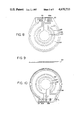
- FIG. 8 is a plan view of a sensing diaphragm structure in accordance with the invention, as viewed from a first side;
- FIG. 9 is a side view of the diaphragm of FIG. 8.
- FIG. 10 is a plan view from the second side of the sensing diaphragm of FIG. 8;
- FIG. 11 is a plan view of the electrode pattern on a first reference plate
- FIG. 12 is a plan view of the electrode pattern on a second reference plate
- FIG. 13 is an exploded view of elements that may be employed in an alternative arrangement for tensioning the isolation diaphragms.
- FIG. 14 is a side sectional view of the arrangement of FIG. 13.
- a differential pressure transducer 10 in accordance with the invention is shown for use in a given range of differential pressures, say 0-30 psi in this example, with an absolute common mode pressure level that can be much higher (e.g. 500-5000 psi).
- Pressures are derived from different junctions 12, 13 in a piping or process system 15, by lines that may contain valving (not shown for simplicity) and that are coupled to opposite sides of the transducer 10 by process joints 17, 18 of conventional design.
- Voltages are applied to the transducer 10 and signal variations are derived therefrom via electrical circuits 20 which include processor circuits 21 that include analog to digital converter capability (not shown).
- Such processing circuits are now utilized in transducer technology for effecting final precise linearization of the signal variations and providing digital values at times and in forms required by an associated system.
- the principal units of the transducers 10, as best seen in FIGS. 2-5, are contained within a cylindrical housing 22 concentric with a central axis except for a side T connection tube 23 through which circuit connections are made.
- a ceramic sensing diaphragm 24 is positioned in a central plane perpendicular to the central axis, within the housing 22.
- the sensing diaphragm 24 has substantially identical electrode patterns on its opposite broad faces, these patterns each comprising a center disk 26 and an outer annulus 28, both concentric about a central axis perpendicular to the plane of the diaphragm 24, and separated by a grounding electrode 27 which minimizes interaction between them.
- Electrodes 26, 28 are made between these electrodes 26, 28 and the associated circuits 20 via peripheral conductive pads 29, 30.
- the elements in the like arrangement on the opposite side of the sensing diaphragm 24 are distinguished by using primed numbers, e.g. 26' and 28', and will not be repetitively described.
- the pads 29, 30, together with a temperature sensitive resistor 31, are on an extending tab 33 on one side of the sensing diaphragm 24 that provides access for external connection within the housing 22.
- the central electrode 26 encompasses the maximum deflection central region of the diaphragm 24, while the outer electrode 28 is close to the confined periphery of the diaphragm 24 and therefore has only minor deflections that are nonetheless for specific purposes as described below.
- each reference plate 34, 36 has inner disk and outer annulus electrodes 40, 42, respectively, disposed in facing and coextensive relation to the like electrodes 26, 28 on the sensing diaphragm 24.
- the opposed sensing electrodes 26, 40 on the reference plate 34 on one side of the diaphragm 24 are matched by another pair 26', 40' on the plate 36 on the opposite side, to form two sensing capacitor pairs which vary in push-pull fashion as the diaphragm 24 deflects.
- conductive pads all designated 29, are available on the extending tab 33 and coupled to these two sensing capacitors to make electrical connections externally.
- a source not shown.
- the reference plates 34, 36 are assembled on opposite sides of the sensing diaphragm 24, an inter-layer connection is made between opposed conductive patterns on the reference plate and sensing diaphragm, so that external wires need be soldered only to the pads on the tab 33 extending from the diaphragm 24.
- two reference capacitors are defined on opposite sides by the outer electrode pairs 28, 42 and 28', 42', with four conductive pads 30a, 30b and 30a', 30b' providing access external to the housing 22.
- leads 44 to and from the various pads 29, 30 provide couplings through the T connection 23 to the circuits 20, while certain of these leads provide couplings to and from the temperature sensitive resistor 31.
- the central assembly of the transducer 10, including the sensing diaphragm 24 and reference plates 34, 36, is isolated and protected within the housing by potting compound 45, as best shown in FIGS. 3 and 7.
- the reference plates 34, 36 are much thicker than the sensing diaphragm 24, which in this example is 0.033", so that there is no measurable bending of the plates 34, 36 under the existing pressures.
- the spacings between the sensing diaphragm 24 and the opposed flat faces of the reference plates 34, 36 are small (e.g. 0.001"), being established by annular spacers 48, 49 (not apparent except in FIG. 4, which is not to scale) around the peripheries of the plates 34, 36.
- the spacers 48, 49 are glass bonding layers that are here about one mil in height, and define both a low volume cavity and a small gap between the facing pairs of electrodes, which are here thin film deposited layers of gold, silver or other conductive material. Though the gap is only about one (1) mil, this is more than enough to allow for maximum deflection of the sensing diaphragm 24 without contact between opposed electrode pairs 26, 40 and 28, 42.
- the glass bonding spacers 48, 49 may be deposited originally as a frit and the assembly of two reference plates 34, 36 separated by the interior diaphragm 24, is held in a fixture as the temperature is raised to vitrification level to bond the elements together and establish a hermetic seal. The view of FIG.
- the gap between opposed electrodes therefore, is only slightly less than the spacing between the diaphragm 24 and a reference plate 34 or 36.
- the thin film electrodes and the temperature sensitive resistor may be deposited by silk screen techniques, so as to assure precise patterns and repeatability in production volumes.
- the reference plates 34, 36 and associated elements are substantially alike in remaining details so only one will be described with particularity and the description will be understood to apply to both.
- the space between is filled by a glass seal ring 56 joining the elements 34, 54 together.
- the edge of the stainless steel seal ring 54 adjacent the backing face 50 has a raised circular bead 60 (best seen in FIG.
- a tensioned isolation diaphragm 62 is stretched across the backing face 50 across the circular bead 60 and glass seal ring 56. The tensioning, which is in the outward direction relative to the backing face 50, is impelled by registration of a stainless steel weld ring 64 onto the seal ring 54 outside the bead 60. Also, the weld ring 64 has a peripheral lip 65 about which the outer periphery of the isolation diaphragm 62 is clamped, as shown only in FIG. 5.
- edge restraint of the peripheral lip enables the outer periphery of the isolation diaphragm 62, in its deflection region, to be clamped down by the weld ring 64 and to induce uniform outward tensioning forces in it in the manner of a tensioned drum head.
- the stainless steel rings 54, 64 are joined together, and to the sandwiched isolation diaphragm 62, by an outer weld 66 around the outer circumference which removes the crimped edge of the isolation diaphragm, as shown in FIG. 4.
- a central axial aperture 67 provides a conduit between the small volume defined by the gap between the sensing diaphragm 34, and the small volume between the backing face 50 and the isolation diaphragm 62, which together define an enclosed cavity.
- the isolation diaphragm 62 is subsequently bowed outwardly when filling the enclosed interior space between the two deflectable diaphragms 24, 62 with an essentially inert oil of one of the commercial types widely used.
- at least one tapered radial aperture 70 in the stainless steel seal ring 54 leads through the housing 22 into the region between the isolation diaphragm 62 and the backing face 50.
- a radial opening 71 in the stainless steel and glass seal rings 54, 56 respectively communicates with the inner part of the radial aperture 70 via a perpendicular bore 72, so that externally supplied oil passes into the interior cavity.
- a hard vacuum is first drawn in the cavity, and oil is then fed into the radial housing aperture 70. Filling is aided by crossed 0.005" lateral grooves 73 in the reference plate 62 surface (FIG. 2), along with a smaller and partially nesting depression in the isolation diaphragm 62.
- sufficient pressure is applied to bow out the isolation diaphragm 62 by approximately 0.001", and a small ball 74 (FIGS.
- the pressurized internal chamber may also be closed off by other known expedients, such as a plug, solder seal or one-way valve (not shown), but the ball press technique is preferred because the volume can be kept very low.
- the total volume of oil in the interior chamber is very low, of the order of 0.001 in 3 . In the practical example being discussed it is approximately 0.0025 in 3 and in any event is held below 0.010 in 3 . This volume is orders of magnitude smaller than oil-filled volumes in prior art pressure tranducers.
- the compliance of the isolation diaphragm 62 is much greater (here more than 100 times) that of the sensing diaphragm 24.
- the isolation diaphragm 62 is a 0.0025" thick sheet of stainless steel, such as 316 alloy, Hastelloy-C or Monel metal, wherein the ceramic sensing diaphragm 24 is a molded and finished ceramic of 0.033" thickness.
- the upper and lower weld rings 64, 64' fit within and define side openings in the transducer housing 22, to couple to the exterior process flanges 17, 18 (FIG. 1 only) and thus provide interior communication between the different fluid pressure sources and the different isolation diaphragms 62, 62' in the two halves.
- An O-ring 65 set into an internal shoulder 78 in the weld ring 64 seals the pressure connection in this region.
- the T connection 23 into the interior of the housing 22 provides access for the circuit connections to the internal electrodes.
- the potting compound 45 filling the interior of the housing 22 about the reference plates 34, 36 and weld rings 64, 64' prevents entry of moisture and provides structural rigidity.
- the isolation diaphragms 62, 62' Prior to the operation of the differential pressure transducer of FIGS. 2-5, the isolation diaphragms 62, 62' have been radially prestressed by the peripheral clamping at the weld ring 64, and by the internal oil pressurization that deflects the diaphragms outwardly.
- the internal pressures may be balanced on each side during this operation by sensing signal variations at the sensing capacitor formed by the internal electrodes 26, 40. Thereafter, pressure variations in the two lines being sensed are communicated through the isolation diaphragms 62, 62' into the pressurized interior cavities, and consequently against the opposite sides of the sensing diaphragm 24.
- the net deflection of the sensing diaphragm as established by the opposite variations in capacitive value of the two inner capacitive pairs is the primary measure of the differential pressure reading.
- the accuracy of the device is affected by certain nonlinearities which are taken into account by transducers in accordance with the present invention.
- a material initial advantage in the configuration derives from the fact that the backing faces 50, 50' are flat and the isolation diaphragms 62, 62' initially bowed. It has heretofore been thought that a convoluted isolation diaphragm must deflect, for good linear operation, over distances more than 0.002".
- the slightly bowed and readily deflectable isolation diaphragms 62, 62' merely straighten to engage flat surfaces at the limiting pressure.
- the sensing diaphragm 24 can operate with a maximum deflection of 40% of the range of deflection of the isolation diaphragm 62 (up to 1.0 mil) and yet remain extremely linear. This means that the cost of fabrication of the unit is substantially lower because only flat surfaces need be provided. Further, the same configuration can be used for different pressure ranges by changing only the sensing diaphragm thickness.
- the pressurizing oil is compressible to a meaningful degree, and also changes in dielectric constant in response to consequent changes in density. At 3000 psi, for example, there is a 11/2% to 2% change in density and a 3% change in dielectric constant.
- the dielectric constant also changes with variations in temperature. While it is known to use separate sensor devices to provide a reference as to pressure level so that some compensation can be introduced, this is not adequately effective for temperature or static pressure variations and introduces substantial undesired costs.
- the present system in using a relatively highly compliant isolation diaphragm 62 together with a stiffer sensing diaphragm 24 and a very low oil volume, minimizes such effects. Pressure variations in the lines are applied with virtually minimum unwanted mechanical or hydraulic impedance to the sensing diaphragm. Only a small amount of deflection need be used, keeping the elements within their linear deflection ranges.
- the reference capacitor pairs are utilized in a unique fashion to sense variations in dielectric constant due to static pressure changes so that the output can be compensated further.
- the two reference capacitors comprising outer electrode pairs 28, 42 and 28', 42' are subject to very little deflection under differential pressure variations because they are close to the sensing diaphragm 24 perimeter, which is fixed.
- the temperature sensitive resistor 31 is formed by thick film techniques onto the extending tab 33 on the sensing diaphragm 24. In this location the resistor 31 is insensitive to differential and static pressure variations. It does, however, provide a precise temperature indication for the transducer 10. The signal from this resistor 31 is applied to the circuits 20 to compensate the outputs of the transducer 10 and make its reading even more reliable and stable.
- this transducer includes the fact that the isolation diaphragm is so compliant and deflects over so small a distance before bottoming out that it cannot as a practical matter become distorted by exceeding its elastic limit.
- the operating range of the transducer can be shifted either positively or negatively by adjustment of process pressures so as to provide a given initial deflection of the sensing diaphragm.
- FIGS. 13 and 14 A different arrangement for radially tensioning the isolation diaphragms, such as the diaphragm 62, is shown in FIGS. 13 and 14.
- the stainless steel ring 54" and the inner glass seal ring 56" have flat surfaces lying in a given plane, except for a circular groove 90 in the ring 54" concentric about the central axis.
- the groove 90 is interior to the outer periphery of the stainless steel ring 54", and to the outer margin of the diaphragm 62.
- the stainless steel weld ring 64" includes a protruding ring or tongue 92 concentric with the central axis and mating within the groove 90 when the transducer is assembled, with allowance for the diaphragm 62 thickness.
- the tongue 92 distorts the diaphragm 62 into the groove 90.
- the portion of the diaphragm 62 encompassed by the tongue 92 is radially prestressed, assuring the flatness of the isolation diaphragm 62 before internal pressurizing begins.
- the flat surfaces on the rings 54", 64" that are disposed both radially inside and radially outside the tongue and groove aid in achieving planarity in the deflection region.
- the outer margin of the diaphragm may be crimped about the outer lip on one of the rings 54", 64" before they are forced together.
- This arrangement not only aids in minimizing tendencies of the diaphragm 62 to have a very slight curvature, but also is somewhat easier to manufacture because the upper surface of the ring 54 can be ground flat in a unitary operation.
Landscapes
- Physics & Mathematics (AREA)
- General Physics & Mathematics (AREA)
- Chemical & Material Sciences (AREA)
- Engineering & Computer Science (AREA)
- Ceramic Engineering (AREA)
- Measuring Fluid Pressure (AREA)
Priority Applications (4)
| Application Number | Priority Date | Filing Date | Title |
|---|---|---|---|
| US06/750,769 US4670733A (en) | 1985-07-01 | 1985-07-01 | Differential pressure transducer |
| CA000512745A CA1280291C (en) | 1985-07-01 | 1986-06-30 | Differential pressure transducer |
| JP61155890A JPS6224120A (ja) | 1985-07-01 | 1986-07-01 | 差動圧力変換器 |
| EP86305114A EP0211519A3 (de) | 1985-07-01 | 1986-07-01 | Kapazitiver Differenzdruckwandler |
Applications Claiming Priority (1)
| Application Number | Priority Date | Filing Date | Title |
|---|---|---|---|
| US06/750,769 US4670733A (en) | 1985-07-01 | 1985-07-01 | Differential pressure transducer |
Publications (1)
| Publication Number | Publication Date |
|---|---|
| US4670733A true US4670733A (en) | 1987-06-02 |
Family
ID=25019093
Family Applications (1)
| Application Number | Title | Priority Date | Filing Date |
|---|---|---|---|
| US06/750,769 Expired - Fee Related US4670733A (en) | 1985-07-01 | 1985-07-01 | Differential pressure transducer |
Country Status (4)
| Country | Link |
|---|---|
| US (1) | US4670733A (de) |
| EP (1) | EP0211519A3 (de) |
| JP (1) | JPS6224120A (de) |
| CA (1) | CA1280291C (de) |
Cited By (65)
| Publication number | Priority date | Publication date | Assignee | Title |
|---|---|---|---|---|
| US4771261A (en) * | 1986-02-10 | 1988-09-13 | Marelli Autronica S.P.A. | Method for achieving the electrical and mechanical interconnection of two bodies, particularly the diaphragm and the support of a thick-film pressure sensor, and devices made by this method |
| US4898035A (en) * | 1988-01-16 | 1990-02-06 | Ngk Insulators, Ltd. | Pressure sensor having sealing member for sealing housing interior with respect to external space |
| US5134887A (en) * | 1989-09-22 | 1992-08-04 | Bell Robert L | Pressure sensors |
| US5349491A (en) * | 1992-11-06 | 1994-09-20 | Kavlico Corporation | Pre-stressed pressure transducer and method of forming same |
| DE4315962A1 (de) * | 1993-04-20 | 1994-10-27 | Landis & Gyr Business Support | Kapsel für einen Drucksensor und Verfahren zur Einkapselung des Drucksensors |
| DE19648048A1 (de) * | 1995-11-21 | 1997-06-19 | Fuji Electric Co Ltd | Druckdetektorvorrichtung zur Druckmessung, basierend auf gemessenen Kapazitätswerten |
| US6295875B1 (en) | 1999-05-14 | 2001-10-02 | Rosemount Inc. | Process pressure measurement devices with improved error compensation |
| US20020113231A1 (en) * | 2000-12-27 | 2002-08-22 | Jerome Stubler | Method for demounting a prestressing cable, and device for carrying it out |
| US6508131B2 (en) | 1999-05-14 | 2003-01-21 | Rosemount Inc. | Process sensor module having a single ungrounded input/output conductor |
| US6516672B2 (en) | 2001-05-21 | 2003-02-11 | Rosemount Inc. | Sigma-delta analog to digital converter for capacitive pressure sensor and process transmitter |
| US20040040384A1 (en) * | 2002-08-30 | 2004-03-04 | Yokogawa Electric Corporation | Differential pressure/pressure transmitter |
| US20040099061A1 (en) * | 1997-12-22 | 2004-05-27 | Mks Instruments | Pressure sensor for detecting small pressure differences and low pressures |
| US20040226382A1 (en) * | 2003-05-16 | 2004-11-18 | Lischer D. Jeffrey | Contaminant deposition control baffle for a capacitive pressure transducer |
| US6839546B2 (en) | 2002-04-22 | 2005-01-04 | Rosemount Inc. | Process transmitter with wireless communication link |
| US20050109114A1 (en) * | 2003-11-20 | 2005-05-26 | Wilson Ronald W. | Cylinder pressure transducer and related method |
| US20050289276A1 (en) * | 2004-06-28 | 2005-12-29 | Karschnia Robert J | Process field device with radio frequency communication |
| US20060070447A1 (en) * | 2004-09-30 | 2006-04-06 | Mks Instruments, Inc. | High-temperature reduced size manometer |
| US20060075823A1 (en) * | 2004-10-07 | 2006-04-13 | Mks Instruments, Inc. | Method and apparatus for forming a reference pressure within a chamber of a capacitance sensor |
| US20060079016A1 (en) * | 2004-10-07 | 2006-04-13 | Mks Instruments, Inc. | Method of forming a seal between a housing and a diaphragm of a capacitance sensor |
| US20060148410A1 (en) * | 2005-01-03 | 2006-07-06 | Nelson Richard L | Wireless process field device diagnostics |
| US20060278007A1 (en) * | 2005-05-27 | 2006-12-14 | Harasyn Donald E | Line pressure measurement using differential pressure sensor |
| US20070073417A1 (en) * | 2005-09-29 | 2007-03-29 | Hedtke Robert C | Pressure transmitter with acoustic pressure sensor |
| US7204150B2 (en) | 2005-01-14 | 2007-04-17 | Mks Instruments, Inc. | Turbo sump for use with capacitive pressure sensor |
| US20070151349A1 (en) * | 2005-12-20 | 2007-07-05 | Mark Schumacher | Pressure sensor with deflectable diaphragm |
| US20070169557A1 (en) * | 2006-01-26 | 2007-07-26 | Harasyn Donald E | Pressure sensor fault detection |
| US20080280568A1 (en) * | 2004-06-28 | 2008-11-13 | Kielb John A | Rf adapter for field device |
| US7484416B1 (en) | 2007-10-15 | 2009-02-03 | Rosemount Inc. | Process control transmitter with vibration sensor |
| US20090161885A1 (en) * | 2007-10-02 | 2009-06-25 | Mark Donaldson | Component for noise reducing earphone |
| US20090307730A1 (en) * | 2008-05-29 | 2009-12-10 | Mark Donaldson | Media enhancement module |
| US20090311971A1 (en) * | 2008-06-17 | 2009-12-17 | Kielb John A | Rf adapter for field device with loop current bypass |
| US20100132471A1 (en) * | 2008-12-03 | 2010-06-03 | Hedtke Robert C | Method and apparatus for pressure measurement using quartz crystal |
| US20100132472A1 (en) * | 2008-12-03 | 2010-06-03 | Willcox Charles R | Method and apparatus for pressure measurement using fill tube |
| US20110003505A1 (en) * | 2009-03-06 | 2011-01-06 | Nigel Greig | In-flight entertainment system connector |
| US20110002474A1 (en) * | 2009-01-29 | 2011-01-06 | Graeme Colin Fuller | Active Noise Reduction System Control |
| US20110053526A1 (en) * | 2009-06-16 | 2011-03-03 | David Matthew Strei | Wireless process communication adapter with improved encapsulation |
| US20110075331A1 (en) * | 2009-05-04 | 2011-03-31 | Nigel Greig | Media Player Holder |
| US20110188668A1 (en) * | 2009-09-23 | 2011-08-04 | Mark Donaldson | Media delivery system |
| US8132464B2 (en) | 2010-07-12 | 2012-03-13 | Rosemount Inc. | Differential pressure transmitter with complimentary dual absolute pressure sensors |
| US8145180B2 (en) | 2004-05-21 | 2012-03-27 | Rosemount Inc. | Power generation for process devices |
| DE102010043043A1 (de) * | 2010-10-28 | 2012-05-03 | Endress + Hauser Gmbh + Co. Kg | Druckmesswandler |
| US8234927B2 (en) | 2010-06-08 | 2012-08-07 | Rosemount Inc. | Differential pressure sensor with line pressure measurement |
| DE102011006517A1 (de) * | 2011-03-31 | 2012-10-04 | Endress + Hauser Gmbh + Co. Kg | Druckfest gekapselter Differenzdrucksensor |
| US8327713B2 (en) | 2008-12-03 | 2012-12-11 | Rosemount Inc. | Method and apparatus for pressure measurement using magnetic property |
| US8429978B2 (en) | 2010-03-30 | 2013-04-30 | Rosemount Inc. | Resonant frequency based pressure sensor |
| US8452255B2 (en) | 2005-06-27 | 2013-05-28 | Rosemount Inc. | Field device with dynamically adjustable power consumption radio frequency communication |
| US8571227B2 (en) | 2005-11-11 | 2013-10-29 | Phitek Systems Limited | Noise cancellation earphone |
| US8626087B2 (en) | 2009-06-16 | 2014-01-07 | Rosemount Inc. | Wire harness for field devices used in a hazardous locations |
| US8694060B2 (en) | 2008-06-17 | 2014-04-08 | Rosemount Inc. | Form factor and electromagnetic interference protection for process device wireless adapters |
| US8752433B2 (en) | 2012-06-19 | 2014-06-17 | Rosemount Inc. | Differential pressure transmitter with pressure sensor |
| US8787848B2 (en) | 2004-06-28 | 2014-07-22 | Rosemount Inc. | RF adapter for field device with low voltage intrinsic safety clamping |
| US8847571B2 (en) | 2008-06-17 | 2014-09-30 | Rosemount Inc. | RF adapter for field device with variable voltage drop |
| US8898036B2 (en) | 2007-08-06 | 2014-11-25 | Rosemount Inc. | Process variable transmitter with acceleration sensor |
| US8929082B2 (en) | 2010-05-17 | 2015-01-06 | Thales Avionics, Inc. | Airline passenger seat modular user interface device |
| US8929948B2 (en) | 2008-06-17 | 2015-01-06 | Rosemount Inc. | Wireless communication adapter for field devices |
| US20150101415A1 (en) * | 2013-10-14 | 2015-04-16 | Vega Grieshaber Kg | Measuring arrangement with a ceramic measuring cell |
| US9048901B2 (en) | 2013-03-15 | 2015-06-02 | Rosemount Inc. | Wireless interface within transmitter |
| CN105021325A (zh) * | 2015-07-02 | 2015-11-04 | 上海自动化仪表有限公司 | 电容式压力传感器 |
| US9310794B2 (en) | 2011-10-27 | 2016-04-12 | Rosemount Inc. | Power supply for industrial process field device |
| US9487295B2 (en) | 2010-11-15 | 2016-11-08 | William James Sim | Vehicle media distribution system using optical transmitters |
| US9654854B2 (en) | 2011-06-01 | 2017-05-16 | Paul Darlington | In-ear device incorporating active noise reduction |
| US9818394B2 (en) | 2009-11-30 | 2017-11-14 | Graeme Colin Fuller | Realisation of controller transfer function for active noise cancellation |
| US9963340B2 (en) | 2015-12-03 | 2018-05-08 | Honeywell International Inc. | Pressure sensor die over pressure protection for high over pressure to operating span ratios |
| US10197462B2 (en) | 2016-05-25 | 2019-02-05 | Honeywell International Inc. | Differential pressure sensor full overpressure protection device |
| US10761524B2 (en) | 2010-08-12 | 2020-09-01 | Rosemount Inc. | Wireless adapter with process diagnostics |
| CN116296041A (zh) * | 2022-12-30 | 2023-06-23 | 重庆市伟岸测器制造股份有限公司 | 差压传感器膜片组装方法 |
Families Citing this family (5)
| Publication number | Priority date | Publication date | Assignee | Title |
|---|---|---|---|---|
| WO1995003534A1 (de) * | 1993-07-24 | 1995-02-02 | Endress + Hauser Gmbh + Co. | Kapazitive drucksensoren mit hoher linearität |
| US10466127B2 (en) | 2010-11-03 | 2019-11-05 | Avgi Engineering, Inc. | Differential pressure transmitter with intrinsic verification |
| US9784633B2 (en) | 2010-11-03 | 2017-10-10 | Avgi Engineering, Inc. | Differential pressure transmitter with intrinsic verification |
| CA2816876C (en) * | 2010-11-03 | 2019-01-08 | Avgi Engineering, Inc. | Differential pressure transmitter with intrinsic verification |
| EP3832281B1 (de) | 2019-12-06 | 2023-09-27 | Eaton Intelligent Power Limited | Druckschalter-membran-abtastelement geeignet für vakuumanwendungen |
Citations (7)
| Publication number | Priority date | Publication date | Assignee | Title |
|---|---|---|---|---|
| US4080830A (en) * | 1976-04-23 | 1978-03-28 | Siemens Aktiengesellschaft | Pressure transducer |
| US4158311A (en) * | 1977-06-09 | 1979-06-19 | Fuji Electric Co., Ltd. | Pressure sensing device |
| US4388833A (en) * | 1980-01-07 | 1983-06-21 | Kabushiki Kaisha Hokushin Denki Seisakusho | Differential pressure gauge |
| US4458537A (en) * | 1981-05-11 | 1984-07-10 | Combustion Engineering, Inc. | High accuracy differential pressure capacitive transducer |
| US4527428A (en) * | 1982-12-30 | 1985-07-09 | Hitachi, Ltd. | Semiconductor pressure transducer |
| US4572000A (en) * | 1983-12-09 | 1986-02-25 | Rosemount Inc. | Pressure sensor with a substantially flat overpressure stop for the measuring diaphragm |
| US4578735A (en) * | 1984-10-12 | 1986-03-25 | Knecht Thomas A | Pressure sensing cell using brittle diaphragm |
Family Cites Families (4)
| Publication number | Priority date | Publication date | Assignee | Title |
|---|---|---|---|---|
| FR2153636A5 (de) * | 1971-09-17 | 1973-05-04 | Sorteberg Jonannes | |
| CA1077294A (en) * | 1976-05-03 | 1980-05-13 | Honeywell Inc. | Pressure transmitter with simplified pressure sensing head |
| GB1558770A (en) * | 1977-05-10 | 1980-01-09 | Bell & Howell Ltd | Differential pressure transducers |
| DE3341735A1 (de) * | 1982-11-25 | 1984-05-30 | Schoppe & Faeser Gmbh, 4950 Minden | Messkapsel fuer einen differenzdruck-messumformer |
-
1985
- 1985-07-01 US US06/750,769 patent/US4670733A/en not_active Expired - Fee Related
-
1986
- 1986-06-30 CA CA000512745A patent/CA1280291C/en not_active Expired - Lifetime
- 1986-07-01 EP EP86305114A patent/EP0211519A3/de not_active Withdrawn
- 1986-07-01 JP JP61155890A patent/JPS6224120A/ja active Pending
Patent Citations (7)
| Publication number | Priority date | Publication date | Assignee | Title |
|---|---|---|---|---|
| US4080830A (en) * | 1976-04-23 | 1978-03-28 | Siemens Aktiengesellschaft | Pressure transducer |
| US4158311A (en) * | 1977-06-09 | 1979-06-19 | Fuji Electric Co., Ltd. | Pressure sensing device |
| US4388833A (en) * | 1980-01-07 | 1983-06-21 | Kabushiki Kaisha Hokushin Denki Seisakusho | Differential pressure gauge |
| US4458537A (en) * | 1981-05-11 | 1984-07-10 | Combustion Engineering, Inc. | High accuracy differential pressure capacitive transducer |
| US4527428A (en) * | 1982-12-30 | 1985-07-09 | Hitachi, Ltd. | Semiconductor pressure transducer |
| US4572000A (en) * | 1983-12-09 | 1986-02-25 | Rosemount Inc. | Pressure sensor with a substantially flat overpressure stop for the measuring diaphragm |
| US4578735A (en) * | 1984-10-12 | 1986-03-25 | Knecht Thomas A | Pressure sensing cell using brittle diaphragm |
Cited By (98)
| Publication number | Priority date | Publication date | Assignee | Title |
|---|---|---|---|---|
| US4771261A (en) * | 1986-02-10 | 1988-09-13 | Marelli Autronica S.P.A. | Method for achieving the electrical and mechanical interconnection of two bodies, particularly the diaphragm and the support of a thick-film pressure sensor, and devices made by this method |
| US4898035A (en) * | 1988-01-16 | 1990-02-06 | Ngk Insulators, Ltd. | Pressure sensor having sealing member for sealing housing interior with respect to external space |
| US5134887A (en) * | 1989-09-22 | 1992-08-04 | Bell Robert L | Pressure sensors |
| US5349491A (en) * | 1992-11-06 | 1994-09-20 | Kavlico Corporation | Pre-stressed pressure transducer and method of forming same |
| DE4315962A1 (de) * | 1993-04-20 | 1994-10-27 | Landis & Gyr Business Support | Kapsel für einen Drucksensor und Verfahren zur Einkapselung des Drucksensors |
| DE19648048A1 (de) * | 1995-11-21 | 1997-06-19 | Fuji Electric Co Ltd | Druckdetektorvorrichtung zur Druckmessung, basierend auf gemessenen Kapazitätswerten |
| US5992240A (en) * | 1995-11-21 | 1999-11-30 | Fuji Electric Co., Ltd. | Pressure detecting apparatus for measuring pressure based on detected capacitance |
| DE19648048C2 (de) * | 1995-11-21 | 2001-11-29 | Fuji Electric Co Ltd | Detektorvorrichtung zur Druckmessung basierend auf gemessenen Kapazitätswerten |
| US20060000289A1 (en) * | 1997-12-22 | 2006-01-05 | Mks Instruments | Pressure sensor for detecting small pressure differences and low pressures |
| US20040099061A1 (en) * | 1997-12-22 | 2004-05-27 | Mks Instruments | Pressure sensor for detecting small pressure differences and low pressures |
| US7284439B2 (en) | 1997-12-22 | 2007-10-23 | Mks Instruments, Inc. | Method for producing a pressure sensor for detecting small pressure differences and low pressures |
| US7389697B2 (en) | 1997-12-22 | 2008-06-24 | Mks Instruments | Pressure sensor for detecting small pressure differences and low pressures |
| US6295875B1 (en) | 1999-05-14 | 2001-10-02 | Rosemount Inc. | Process pressure measurement devices with improved error compensation |
| US6508131B2 (en) | 1999-05-14 | 2003-01-21 | Rosemount Inc. | Process sensor module having a single ungrounded input/output conductor |
| US20020113231A1 (en) * | 2000-12-27 | 2002-08-22 | Jerome Stubler | Method for demounting a prestressing cable, and device for carrying it out |
| US6516672B2 (en) | 2001-05-21 | 2003-02-11 | Rosemount Inc. | Sigma-delta analog to digital converter for capacitive pressure sensor and process transmitter |
| US6839546B2 (en) | 2002-04-22 | 2005-01-04 | Rosemount Inc. | Process transmitter with wireless communication link |
| US6796185B2 (en) * | 2002-08-30 | 2004-09-28 | Yokogawa Electric Corporation | Differential pressure/pressure transmitter |
| US20040040384A1 (en) * | 2002-08-30 | 2004-03-04 | Yokogawa Electric Corporation | Differential pressure/pressure transmitter |
| US6993973B2 (en) | 2003-05-16 | 2006-02-07 | Mks Instruments, Inc. | Contaminant deposition control baffle for a capacitive pressure transducer |
| US20040226382A1 (en) * | 2003-05-16 | 2004-11-18 | Lischer D. Jeffrey | Contaminant deposition control baffle for a capacitive pressure transducer |
| US20050109114A1 (en) * | 2003-11-20 | 2005-05-26 | Wilson Ronald W. | Cylinder pressure transducer and related method |
| US6955090B2 (en) | 2003-11-20 | 2005-10-18 | General Electric Company | Cylinder pressure transducer and related method |
| US8145180B2 (en) | 2004-05-21 | 2012-03-27 | Rosemount Inc. | Power generation for process devices |
| US7956738B2 (en) | 2004-06-28 | 2011-06-07 | Rosemount Inc. | Process field device with radio frequency communication |
| US20080280568A1 (en) * | 2004-06-28 | 2008-11-13 | Kielb John A | Rf adapter for field device |
| US8787848B2 (en) | 2004-06-28 | 2014-07-22 | Rosemount Inc. | RF adapter for field device with low voltage intrinsic safety clamping |
| US8160535B2 (en) | 2004-06-28 | 2012-04-17 | Rosemount Inc. | RF adapter for field device |
| US20070285224A1 (en) * | 2004-06-28 | 2007-12-13 | Karschnia Robert J | Process field device with radio frequency communication |
| US20050289276A1 (en) * | 2004-06-28 | 2005-12-29 | Karschnia Robert J | Process field device with radio frequency communication |
| US7262693B2 (en) | 2004-06-28 | 2007-08-28 | Rosemount Inc. | Process field device with radio frequency communication |
| US20060070447A1 (en) * | 2004-09-30 | 2006-04-06 | Mks Instruments, Inc. | High-temperature reduced size manometer |
| US7201057B2 (en) | 2004-09-30 | 2007-04-10 | Mks Instruments, Inc. | High-temperature reduced size manometer |
| US20060079016A1 (en) * | 2004-10-07 | 2006-04-13 | Mks Instruments, Inc. | Method of forming a seal between a housing and a diaphragm of a capacitance sensor |
| US7141447B2 (en) | 2004-10-07 | 2006-11-28 | Mks Instruments, Inc. | Method of forming a seal between a housing and a diaphragm of a capacitance sensor |
| US20060075823A1 (en) * | 2004-10-07 | 2006-04-13 | Mks Instruments, Inc. | Method and apparatus for forming a reference pressure within a chamber of a capacitance sensor |
| US7624643B2 (en) | 2004-10-07 | 2009-12-01 | Mks Instruments, Inc. | Method and apparatus for forming a reference pressure within a chamber of a capacitance sensor |
| US20070023140A1 (en) * | 2004-10-07 | 2007-02-01 | Mks Instruments, Inc. | Method and apparatus for forming a reference pressure within a chamber of a capacitance sensor |
| US20070026562A1 (en) * | 2004-10-07 | 2007-02-01 | Mks Instruments, Inc. | Method of forming a seal between a housing and a diaphragm of a capacitance sensor |
| US7137301B2 (en) | 2004-10-07 | 2006-11-21 | Mks Instruments, Inc. | Method and apparatus for forming a reference pressure within a chamber of a capacitance sensor |
| US7316163B2 (en) | 2004-10-07 | 2008-01-08 | Mks Instruments | Method of forming a seal between a housing and a diaphragm of a capacitance sensor |
| US20060148410A1 (en) * | 2005-01-03 | 2006-07-06 | Nelson Richard L | Wireless process field device diagnostics |
| US7680460B2 (en) | 2005-01-03 | 2010-03-16 | Rosemount Inc. | Wireless process field device diagnostics |
| US7204150B2 (en) | 2005-01-14 | 2007-04-17 | Mks Instruments, Inc. | Turbo sump for use with capacitive pressure sensor |
| US7334484B2 (en) | 2005-05-27 | 2008-02-26 | Rosemount Inc. | Line pressure measurement using differential pressure sensor |
| US20060278007A1 (en) * | 2005-05-27 | 2006-12-14 | Harasyn Donald E | Line pressure measurement using differential pressure sensor |
| US8452255B2 (en) | 2005-06-27 | 2013-05-28 | Rosemount Inc. | Field device with dynamically adjustable power consumption radio frequency communication |
| US7379792B2 (en) | 2005-09-29 | 2008-05-27 | Rosemount Inc. | Pressure transmitter with acoustic pressure sensor |
| US20070073417A1 (en) * | 2005-09-29 | 2007-03-29 | Hedtke Robert C | Pressure transmitter with acoustic pressure sensor |
| US8571227B2 (en) | 2005-11-11 | 2013-10-29 | Phitek Systems Limited | Noise cancellation earphone |
| WO2007075290A1 (en) * | 2005-12-20 | 2007-07-05 | Rosemount Inc. | Pressure sensor with deflectable diaphragm |
| US20070151349A1 (en) * | 2005-12-20 | 2007-07-05 | Mark Schumacher | Pressure sensor with deflectable diaphragm |
| US7415886B2 (en) | 2005-12-20 | 2008-08-26 | Rosemount Inc. | Pressure sensor with deflectable diaphragm |
| US20070169557A1 (en) * | 2006-01-26 | 2007-07-26 | Harasyn Donald E | Pressure sensor fault detection |
| US7308830B2 (en) | 2006-01-26 | 2007-12-18 | Rosemount Inc. | Pressure sensor fault detection |
| US8898036B2 (en) | 2007-08-06 | 2014-11-25 | Rosemount Inc. | Process variable transmitter with acceleration sensor |
| US8666085B2 (en) | 2007-10-02 | 2014-03-04 | Phitek Systems Limited | Component for noise reducing earphone |
| US20090161885A1 (en) * | 2007-10-02 | 2009-06-25 | Mark Donaldson | Component for noise reducing earphone |
| US7484416B1 (en) | 2007-10-15 | 2009-02-03 | Rosemount Inc. | Process control transmitter with vibration sensor |
| US20090307730A1 (en) * | 2008-05-29 | 2009-12-10 | Mark Donaldson | Media enhancement module |
| US8694060B2 (en) | 2008-06-17 | 2014-04-08 | Rosemount Inc. | Form factor and electromagnetic interference protection for process device wireless adapters |
| US8049361B2 (en) | 2008-06-17 | 2011-11-01 | Rosemount Inc. | RF adapter for field device with loop current bypass |
| US20090311971A1 (en) * | 2008-06-17 | 2009-12-17 | Kielb John A | Rf adapter for field device with loop current bypass |
| US8929948B2 (en) | 2008-06-17 | 2015-01-06 | Rosemount Inc. | Wireless communication adapter for field devices |
| US8847571B2 (en) | 2008-06-17 | 2014-09-30 | Rosemount Inc. | RF adapter for field device with variable voltage drop |
| US8327713B2 (en) | 2008-12-03 | 2012-12-11 | Rosemount Inc. | Method and apparatus for pressure measurement using magnetic property |
| US7954383B2 (en) | 2008-12-03 | 2011-06-07 | Rosemount Inc. | Method and apparatus for pressure measurement using fill tube |
| US20100132471A1 (en) * | 2008-12-03 | 2010-06-03 | Hedtke Robert C | Method and apparatus for pressure measurement using quartz crystal |
| US7870791B2 (en) | 2008-12-03 | 2011-01-18 | Rosemount Inc. | Method and apparatus for pressure measurement using quartz crystal |
| US20100132472A1 (en) * | 2008-12-03 | 2010-06-03 | Willcox Charles R | Method and apparatus for pressure measurement using fill tube |
| US20110002474A1 (en) * | 2009-01-29 | 2011-01-06 | Graeme Colin Fuller | Active Noise Reduction System Control |
| US20110003505A1 (en) * | 2009-03-06 | 2011-01-06 | Nigel Greig | In-flight entertainment system connector |
| US20110075331A1 (en) * | 2009-05-04 | 2011-03-31 | Nigel Greig | Media Player Holder |
| US20110053526A1 (en) * | 2009-06-16 | 2011-03-03 | David Matthew Strei | Wireless process communication adapter with improved encapsulation |
| US8626087B2 (en) | 2009-06-16 | 2014-01-07 | Rosemount Inc. | Wire harness for field devices used in a hazardous locations |
| US9674976B2 (en) | 2009-06-16 | 2017-06-06 | Rosemount Inc. | Wireless process communication adapter with improved encapsulation |
| US20110188668A1 (en) * | 2009-09-23 | 2011-08-04 | Mark Donaldson | Media delivery system |
| US9818394B2 (en) | 2009-11-30 | 2017-11-14 | Graeme Colin Fuller | Realisation of controller transfer function for active noise cancellation |
| US8429978B2 (en) | 2010-03-30 | 2013-04-30 | Rosemount Inc. | Resonant frequency based pressure sensor |
| US8929082B2 (en) | 2010-05-17 | 2015-01-06 | Thales Avionics, Inc. | Airline passenger seat modular user interface device |
| US8234927B2 (en) | 2010-06-08 | 2012-08-07 | Rosemount Inc. | Differential pressure sensor with line pressure measurement |
| US8132464B2 (en) | 2010-07-12 | 2012-03-13 | Rosemount Inc. | Differential pressure transmitter with complimentary dual absolute pressure sensors |
| US10761524B2 (en) | 2010-08-12 | 2020-09-01 | Rosemount Inc. | Wireless adapter with process diagnostics |
| DE102010043043A1 (de) * | 2010-10-28 | 2012-05-03 | Endress + Hauser Gmbh + Co. Kg | Druckmesswandler |
| US9487295B2 (en) | 2010-11-15 | 2016-11-08 | William James Sim | Vehicle media distribution system using optical transmitters |
| US9054222B2 (en) | 2011-03-31 | 2015-06-09 | Endress + Hauser Gmbh + Co. Kg | Pressure resistently encapsulated, pressure difference sensor |
| DE102011006517A1 (de) * | 2011-03-31 | 2012-10-04 | Endress + Hauser Gmbh + Co. Kg | Druckfest gekapselter Differenzdrucksensor |
| US9654854B2 (en) | 2011-06-01 | 2017-05-16 | Paul Darlington | In-ear device incorporating active noise reduction |
| US9310794B2 (en) | 2011-10-27 | 2016-04-12 | Rosemount Inc. | Power supply for industrial process field device |
| US8752433B2 (en) | 2012-06-19 | 2014-06-17 | Rosemount Inc. | Differential pressure transmitter with pressure sensor |
| US9048901B2 (en) | 2013-03-15 | 2015-06-02 | Rosemount Inc. | Wireless interface within transmitter |
| US20150101415A1 (en) * | 2013-10-14 | 2015-04-16 | Vega Grieshaber Kg | Measuring arrangement with a ceramic measuring cell |
| US9880064B2 (en) * | 2013-10-14 | 2018-01-30 | Vega Grieshaber Kg | Measuring arrangement with a ceramic measuring cell |
| CN105021325B (zh) * | 2015-07-02 | 2017-11-14 | 上海自动化仪表有限公司 | 电容式压力传感器 |
| CN105021325A (zh) * | 2015-07-02 | 2015-11-04 | 上海自动化仪表有限公司 | 电容式压力传感器 |
| US9963340B2 (en) | 2015-12-03 | 2018-05-08 | Honeywell International Inc. | Pressure sensor die over pressure protection for high over pressure to operating span ratios |
| US10197462B2 (en) | 2016-05-25 | 2019-02-05 | Honeywell International Inc. | Differential pressure sensor full overpressure protection device |
| CN116296041A (zh) * | 2022-12-30 | 2023-06-23 | 重庆市伟岸测器制造股份有限公司 | 差压传感器膜片组装方法 |
Also Published As
| Publication number | Publication date |
|---|---|
| CA1280291C (en) | 1991-02-19 |
| EP0211519A2 (de) | 1987-02-25 |
| JPS6224120A (ja) | 1987-02-02 |
| EP0211519A3 (de) | 1988-07-27 |
Similar Documents
| Publication | Publication Date | Title |
|---|---|---|
| EP0211519A2 (de) | Kapazitiver Differenzdruckwandler | |
| US4562742A (en) | Capacitive pressure transducer | |
| US4301492A (en) | Pressure-sensing transducer | |
| US4388668A (en) | Capacitive pressure transducer | |
| US5134887A (en) | Pressure sensors | |
| JP3133759B2 (ja) | 応力遮断用凹部付き圧力トランスミッタ | |
| US3965746A (en) | Pressure transducer | |
| US4829826A (en) | Differential-pressure transducer | |
| US4287553A (en) | Capacitive pressure transducer | |
| US4944187A (en) | Multimodulus pressure sensor | |
| US6205861B1 (en) | Transducer having temperature compensation | |
| US4163395A (en) | Pressure transmitter with simplified pressure sensing head | |
| US5757608A (en) | Compensated pressure transducer | |
| GB1581903A (en) | Capacitor transducer | |
| US4168517A (en) | Capacitive pressure transducer | |
| US4458537A (en) | High accuracy differential pressure capacitive transducer | |
| CA1239806A (en) | Capacitive sensing cell made of brittle material | |
| EP0165302A1 (de) | Druckfühler mit einem wesentlich flachen überdruckstop für das messungsdiaphragma | |
| CN1129980A (zh) | 电容压力传感器 | |
| US4680971A (en) | Dual diaphragm differential pressure transducer | |
| US4974117A (en) | Dual diaphragm capacitive differential pressure transducer | |
| US4172387A (en) | Pressure responsive apparatus | |
| US5034848A (en) | Low pressure sensor | |
| JPS59145940A (ja) | 差圧・圧力伝送器 | |
| JPS5855833A (ja) | 差圧測定装置 |
Legal Events
| Date | Code | Title | Description |
|---|---|---|---|
| AS | Assignment |
Owner name: BELL MICROSENSORS, INC., A CORP. OF CA. Free format text: ASSIGNMENT OF ASSIGNORS INTEREST.;ASSIGNOR:BELL, ROBERT L.;REEL/FRAME:004425/0588 Effective date: 19850626 |
|
| CC | Certificate of correction | ||
| REMI | Maintenance fee reminder mailed | ||
| LAPS | Lapse for failure to pay maintenance fees | ||
| STCH | Information on status: patent discontinuation |
Free format text: PATENT EXPIRED DUE TO NONPAYMENT OF MAINTENANCE FEES UNDER 37 CFR 1.362 |
|
| FP | Lapsed due to failure to pay maintenance fee |
Effective date: 19910602 |
|
| DD | Disclaimer and dedication filed |
Free format text: 910906 |