US465709A - earwood - Google Patents
earwood Download PDFInfo
- Publication number
- US465709A US465709A US465709DA US465709A US 465709 A US465709 A US 465709A US 465709D A US465709D A US 465709DA US 465709 A US465709 A US 465709A
- Authority
- US
- United States
- Prior art keywords
- sweep
- standard
- plow
- mold
- point
- Prior art date
- Legal status (The legal status is an assumption and is not a legal conclusion. Google has not performed a legal analysis and makes no representation as to the accuracy of the status listed.)
- Expired - Lifetime
Links
Images


Classifications
-
- A—HUMAN NECESSITIES
- A01—AGRICULTURE; FORESTRY; ANIMAL HUSBANDRY; HUNTING; TRAPPING; FISHING
- A01B—SOIL WORKING IN AGRICULTURE OR FORESTRY; PARTS, DETAILS, OR ACCESSORIES OF AGRICULTURAL MACHINES OR IMPLEMENTS, IN GENERAL
- A01B35/00—Other machines for working soil
- A01B35/20—Tools; Details
- A01B35/22—Non-rotating tools; Resilient or flexible mounting of rigid tools
- A01B35/26—Rigid tools
Definitions
- This invention relates to plows which are provided with detachable, interchangeable, and adjustable parts, whereby the plow is adapted for various kinds of work and soil of varying character in the same or different 10- calities.
- the object of the invention is to provide a plow of the aforesaid character with as few parts as possible and with a minimum number of independent removable fastenings, and in which the detachable and the adjustable parts will obtain as broad a bearing as possible in the various positions, and which parts when located will be held in the adjusted or required position by positive means aside from the friction between the meeting and overlap ping faces of the parts.
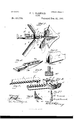
- Figure 1 is a perspective view of a plow embodying my invention, the upper portion of the handle and the front end of the beam being broken away.
- Fig. 2 is a side view of the plow, partly in section and with parts broken away.
- Fig. 3 is a top plan view of the plow, the upper portion of the standard being broken away, one of the sweeps and one of the mold-boards being removed and the adjustment of the other mold-board being shown in dotted lines.
- Fig. 1 is a perspective view of the heel.
- Fig. 5 is a perspective View of the lower rear portion of the standard.
- Fig. 6 is a crosssection of the lower portion of the standard and the heel on the line 6 (3 of Fig.
- Fig. 7 is a perspective view of the adjustable sweep.
- Fig. 8 is a detail perspective view of the sweep-stock, a portion of one of the sweep supporting arms being broken away.
- Fig. 8 is a perspective view of the belt for securing the sweep-stock to the standard, the upper threadedportion of the said bolt being broken away.
- Fig. 9 is a cross-section of a sweep and asweepsupporting arm, showing a tongue-and-groove connection between the meeting faces.
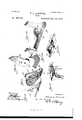
- Fig. 10 is a perspective view of the point of the standard.
- Fig. 11 is a perspective view of the detachable foot.
- Fig. 12 is aperspective viewof thebreastorcasting intermediate the plow-point and the mold-boards.
- FIG. 13 is a perspective view of one of the mold-boards.
- Fig. 14. is a perspective View of the plow-point.
- Fig. 15 is a perspective view of the upper portion of the standard.
- Fig. 16 is a perspective View of the wedge which is interposed between the top of the standard and the under side of the beam.
- Fig. 17 is a side view of a turn-plow constructed in accordance with it and embodying my invention.
- Fig. 18 is a section on the line 18 18 of Fig. 17, looking to the left, as indicated by the arrow.
- Fig. 19 is a section on the line 19 19 of Fig. 18, looking to the left,
- Fig. 20 is a front view of the plow shown in Fig. 17, illustrating the several positions of the moldboards and the width of the corresponding points by dotted lines.
- Fig. 21 is a detail perspective view of the rear portion of the detachable landside.
- Fig. 22 is a detail perspective view of the rear portion of the rear extension of the said support for the point and mold-board.
- the standard A in general construction and outline is of ordinary appearance, and the beam 13 and handles 0 are of well-known arrangement. prising two wings, as most clearly shown in Fig. 11, and is provided with a rearwardlyprojecting fastening-plate (l, which overlaps and is bolted to the standard.
- the point E which is double, is fitted on the point of the foot D and is firmly held thereon by the lug e on one part embracing the edge of the foot I) and, for greater stability, entering the
- the foot D is double, com-' notch d, and a bolt a passing through coincident openings 6' and d in the said point and shoe.
- the upper edge of the point is rabbeted to form the projecting portion 6
- the breast F also double, is constructed to rest on the foot D, and its lower edge conforms to the upper edge of the point and is rabbeted to form the projecting portion f, which extends beneath the aforesaid projecting portion 6 the surfaces of the point and breast being flush.
- the upper edge of the breast is provided with two seats f f, one on each side of a medial line, which I are circular in outline and beveled from the the lower ends of the mold-boards are formed vention applied to a single-turn plow.
- the inner edges of the mold-boards are straight and come together on a line forming a prolongation of the medial cutting-edge of the point and breast.
- the pin g projecting from the rear of the mold-boards is adapted to enter one of the series of notches d in the circular edge of the foot to hold the mold-boards in the proper position in a positive manner. Obviously any positive locking means between the moldboards and the foot will answer equally as well as the pin g and the notches d".
- the upper end of each half of the foot is circular, the circle having the bolt-opening d for its center.
- Fig. 3 show the mold-board intermediate of its extreme adjustments, and the dotted lines show the extreme limits of adjustment.
- the notches d are provided in sufficient number and arranged to secure the proper adjustment.
- Figs. 17 to 20, inclusive illustrate the in- The point Eand the footD are single; butthe construction and the relative arrangement of the parts-i. e., the mold-board and the fastening devices between it and the foot-are precisely the same as the corresponding parts in the double plow.
- the breast is dispensed with in this form of plow and the curved and beveled seat for the lower end of the mold-board is formed in the upper edge of the point E, 'as shown at e.
- the rearwardlyprojecting fastening-plate D extends to the rear of the standard and is fastened there o near the front and the rear edge thereof.
- the landside H tapers at its upper edge to the plane of the plate D and is fastened thereto by the headed lugs h, one near the front, the other near the rear, end of the said landside, which engage with the beveled edges of the slots h,
- the point E is in position, it will overlap the front end of the landside and prevent the latter being pushedforward and becoming accidentally disengaged.
- the point D is provided with a projecting portion D near its lower edge, which engages with the lower edge of the foot, and which, with the headed lug D on the said point and the slot (1 in the foot, holds the point in place.
- Fig. 20 the full lines indicate the position of the mold-board and the width of point when a light furrow is made.
- the dotted lines 2 2 represent the position of the mold-board and the corresponding width of point when a wider furrow is desired.
- the dotted lines 3 3 illustrate the position of the mold-board and the corresponding width of point when a still wider furrow is required to be made. The points are made interchangeable, and when the mold-board is adjusted to one of the positions 1,2, or 3 the point corresponding in width to the position of the mold-board must be attached.
- the seat I for the sweep-stock J is formed on the arc of a perfect circle, and the under side of the sweep-stock is correspondingly formed on the arc of a true circle, so that the said sweep-stock in its various adjustments on the said seat will obtain a bearin g throughout its length, thereby obviating the strain which exists when the said sweep stock touches at two points only, one near each end, and which requires the said sweep-stock to be heavily cast in order to withstand the said strain.
- the sweep-stock is considerably wider than the standard, and is channeled or grooved in its under side to receive the said seat I.
- the flanges formed by the said channel or groovet' in the sweep-stock embrace the sides of the standard on each side of the seat I and prevent any lateral movement of the said sweep-stock.
- the fastening-bolt K is angular, and its upper portion is reduced and threaded.
- the angular portion is adapted to enter one of a series of angular openingsj in the sweep-stock, and the nut is, when screwed home, holds the sweep-stock firmly in place on its seat.
- the angular openings j are connected by a narrow passage-way sufficiently wide to permit the threaded portion is to pass from one opening to the other in the adjustment of the sweep-stock on the seat I.
- the threaded portion 70 is sufficiently long to admit of the disengagement of the sweep-stock from the angular portion of the bolt K, when adjusting the same, without removing the nut orwhollydisengagingthesweep-stockfromthe said bolt.
- the arms J projected from the diametrically-opposite sides of the sweep-- stock, are curved in crosssection and slotted longitudinally.
- ThesweepsL are secured each to the said arms by a bolt Z, which passes through thesaidslot in the arm J, and are prevented from turning on the said bolt by a pin or lug Z, which extends into the slot through which the bolt Zpasses.
- the sweep By loosening the bolt Z the sweep can be moved in or out and is held in the desired position by retightening the said bolt.
- the pin Z may be dispensed with and the meeting faces of the sweep and the arm J may have a tongue and -groove connection, as shown in Fig. 9.
- the heel M is detachable and tapers at its forward end to the plane of the sides and the bottom of the standard, and is provided on its upper or top side with a channel m, which flares from top to bottom to receive ribs m, which project from the sides of the standard near the rear end thereof.
- These ribs m are of uniform cross-section for the greater portion of their length from the front ends and flare or spread rapidly at their rear ends to bind in the channel on and hold the heel firmly and securely 011 the standard-rod. A smart blow on the rear end of the heel will disengage it from the standard.
- the T-head a of the standard is provided with corresponding notches a in its edges, which receive depending projections n on the wedge N, thereby forming a positive means of connection between the said Wedge and the T-head of the standard.
- the longitudinal slot at in the wedge permits the said wedge to be adjusted to raise or lower the front end of the beam, and the vertical flanges n prevent any lateral movement of the wedge relative to the beam.
- the headed lugs h and D are tapering on their sides and that the edges of the slots h and d are of a corresponding taper.
- the relative position of the lug on the moldboard and the notches on the foot may be changed-'i. a, the lug may be provided on the foot and the notches in the mold-board-or mutually-interlocking teeth and depressions may be provided between the meeting faces of the m old-board and the feet at any convenient point, the purpose of said construction being to hold the mold-board in the required position in a positive manner.
- the lateral projections m may flare their entire length or only part,as shown,the latter being the preferable form.
- the bolt-openings in the sweep stock may be other than angular to correspond with the fastening-bolt, which may be round, oblong, or of any desired pattern in cross-section.
- the object is to have the fastening-bolt and the said bolt-openings mutually interlock to hold the sweep-stock firmly and securely on its seat. .
- the upper surface of the sweep-stock is curved and parallel with the under surface, therebypermitting the nut to obtain a broad and even purchase when screwed home.
- the combination with a moldboard support having a seat formed on the are of a circle and beveled and havingthe ing a projection to enter one of the said notches, and a fastening to secure the mold.- board to the said support, substantially as described.
- the combination with the sweep -stock having a laterally projecting arm which is longitudinally slotted, of a sweep having the projection Z to enter the said slot, and the fastening-bolt to secure the sweep on the said arm, substantially as set forth.
Landscapes
- Life Sciences & Earth Sciences (AREA)
- Engineering & Computer Science (AREA)
- Mechanical Engineering (AREA)
- Soil Sciences (AREA)
- Environmental Sciences (AREA)
- Soil Working Implements (AREA)
Description
(No Model.) 4Sheets-Sheet 1.
H. L. HARWOOD.
I l ,h enryl 112010001,
@513 1 aflozmeqof (No Model.) 4 Sheets-Sheet 2.
\ H. L. HARWOOD.
PLOW.
No. 465,709. PatentedDec. 22, 1891.
(No Model.) 4 Sheets-Sheet 3.
H. L. HARWOOD.
PLOW.
No. 465,709. 7 Patented Dec. 22, 1891.
lmitvwooe (No Model.) 4 SheetsSheet 4 H. L. HARWOOD.
- I PLOW.
N0.465,709. Patented Dec 22, 1891.
STATES N 1TB HENRY L. IIARWOOD, OF NORFOLK, VIRGINIA.
PLOW.
SPECIFICATION forming part of Letters Patent No. 465,709, dated December 22, 189 1.
Application filed July 1,1891. erial No. 898,110. (No model.)
T on whom it may concern:
Be it known that I, HENRY L. Hanwoona citizen of the United States, residing at Norfolk, in the county of Norfolk and State of Virginia, have invented certain new and useful Improvements in Flows; and I do hereby declare the following to be a full, clear, and exact description of the invention, such as will enable others skilled in the art to which it appertains to make and use the same.
This invention relates to plows which are provided with detachable, interchangeable, and adjustable parts, whereby the plow is adapted for various kinds of work and soil of varying character in the same or different 10- calities.
The object of the invention is to provide a plow of the aforesaid character with as few parts as possible and with a minimum number of independent removable fastenings, and in which the detachable and the adjustable parts will obtain as broad a bearing as possible in the various positions, and which parts when located will be held in the adjusted or required position by positive means aside from the friction between the meeting and overlap ping faces of the parts.
The improvement consists of the novel features and the peculiar construction and combination of the parts, which will be hereinafter more fully described and claimed, and which are shown in the annexed drawings, in which Figure 1 is a perspective view of a plow embodying my invention, the upper portion of the handle and the front end of the beam being broken away. Fig. 2 is a side view of the plow, partly in section and with parts broken away. Fig. 3 is a top plan view of the plow, the upper portion of the standard being broken away, one of the sweeps and one of the mold-boards being removed and the adjustment of the other mold-board being shown in dotted lines. Fig. 1 is a perspective view of the heel. Fig. 5 is a perspective View of the lower rear portion of the standard. Fig. 6 is a crosssection of the lower portion of the standard and the heel on the line 6 (3 of Fig.
Fig. 7 is a perspective view of the adjustable sweep. Fig. 8 is a detail perspective view of the sweep-stock, a portion of one of the sweep supporting arms being broken away. Fig. 8 is a perspective view of the belt for securing the sweep-stock to the standard, the upper threadedportion of the said bolt being broken away. Fig. 9 is a cross-section of a sweep and asweepsupporting arm, showing a tongue-and-groove connection between the meeting faces. Fig. 10 is a perspective view of the point of the standard. Fig. 11 is a perspective view of the detachable foot. Fig. 12 is aperspective viewof thebreastorcasting intermediate the plow-point and the mold-boards. Fig. 13 is a perspective view of one of the mold-boards. Fig. 14. is a perspective View of the plow-point. Fig. 15 is a perspective view of the upper portion of the standard. Fig. 16 is a perspective View of the wedge which is interposed between the top of the standard and the under side of the beam. Fig. 17 is a side view of a turn-plow constructed in accordance with it and embodying my invention. Fig. 18 is a section on the line 18 18 of Fig. 17, looking to the left, as indicated by the arrow. Fig. 19 is a section on the line 19 19 of Fig. 18, looking to the left,
' as shown by the arrow, a portion of the standard being broken away to showthe fastening between the landside and the rearwardlyprojecting fastening-plate of the foot, showing the rear fastening in full lines. Fig. 20 is a front view of the plow shown in Fig. 17, illustrating the several positions of the moldboards and the width of the corresponding points by dotted lines. Fig. 21 is a detail perspective view of the rear portion of the detachable landside. Fig. 22 is a detail perspective view of the rear portion of the rear extension of the said support for the point and mold-board.
Similar letters refer to corresponding parts in the several views of the drawings.
The standard A in general construction and outline is of ordinary appearance, and the beam 13 and handles 0 are of well-known arrangement. prising two wings, as most clearly shown in Fig. 11, and is provided with a rearwardlyprojecting fastening-plate (l, which overlaps and is bolted to the standard. The point E, which is double, is fitted on the point of the foot D and is firmly held thereon by the lug e on one part embracing the edge of the foot I) and, for greater stability, entering the The foot D is double, com-' notch d, and a bolt a passing through coincident openings 6' and d in the said point and shoe. The upper edge of the point is rabbeted to form the projecting portion 6 The breast F, also double, is constructed to rest on the foot D, and its lower edge conforms to the upper edge of the point and is rabbeted to form the projecting portion f, which extends beneath the aforesaid projecting portion 6 the surfaces of the point and breast being flush. The upper edge of the breast is provided with two seats f f, one on each side of a medial line, which I are circular in outline and beveled from the the lower ends of the mold-boards are formed vention applied to a single-turn plow.
on the arc of a circle, having the fasteningbolts 9 for their centers. The inner edges of the mold-boards are straight and come together on a line forming a prolongation of the medial cutting-edge of the point and breast. The pin g projecting from the rear of the mold-boards, is adapted to enter one of the series of notches d in the circular edge of the foot to hold the mold-boards in the proper position in a positive manner. Obviously any positive locking means between the moldboards and the foot will answer equally as well as the pin g and the notches d". The upper end of each half of the foot is circular, the circle having the bolt-opening d for its center.
The full lines in Fig. 3 show the mold-board intermediate of its extreme adjustments, and the dotted lines show the extreme limits of adjustment. The notches d are provided in sufficient number and arranged to secure the proper adjustment.
The foregoing shows the invention in its special construction as applied to a double plow.
Figs. 17 to 20, inclusive, illustrate the in- The point Eand the footD are single; butthe construction and the relative arrangement of the parts-i. e., the mold-board and the fastening devices between it and the foot-are precisely the same as the corresponding parts in the double plow. The breast is dispensed with in this form of plow and the curved and beveled seat for the lower end of the mold-board is formed in the upper edge of the point E, 'as shown at e. The rearwardlyprojecting fastening-plate D extends to the rear of the standard and is fastened there o near the front and the rear edge thereof. The landside H tapers at its upper edge to the plane of the plate D and is fastened thereto by the headed lugs h, one near the front, the other near the rear, end of the said landside, which engage with the beveled edges of the slots h,
the point E is in position, it will overlap the front end of the landside and prevent the latter being pushedforward and becoming accidentally disengaged. The point D is provided with a projecting portion D near its lower edge, which engages with the lower edge of the foot, and which, with the headed lug D on the said point and the slot (1 in the foot, holds the point in place. The lower end of the mold-board, fitting in the curved seat formed in the point, prevents any accidental displacement of the said point.
In Fig. 20 the full lines indicate the position of the mold-board and the width of point when a light furrow is made. The dotted lines 2 2 represent the position of the mold-board and the corresponding width of point when a wider furrow is desired. The dotted lines 3 3 illustrate the position of the mold-board and the corresponding width of point when a still wider furrow is required to be made. The points are made interchangeable, and when the mold-board is adjusted to one of the positions 1,2, or 3 the point corresponding in width to the position of the mold-board must be attached.
The seat I for the sweep-stock J is formed on the arc of a perfect circle, and the under side of the sweep-stock is correspondingly formed on the arc of a true circle, so that the said sweep-stock in its various adjustments on the said seat will obtain a bearin g throughout its length, thereby obviating the strain which exists when the said sweep stock touches at two points only, one near each end, and which requires the said sweep-stock to be heavily cast in order to withstand the said strain. The sweep-stock is considerably wider than the standard, and is channeled or grooved in its under side to receive the said seat I. The flanges formed by the said channel or groovet' in the sweep-stock embrace the sides of the standard on each side of the seat I and prevent any lateral movement of the said sweep-stock. The fastening-bolt K is angular, and its upper portion is reduced and threaded. The angular portion is adapted to enter one of a series of angular openingsj in the sweep-stock, and the nut is, when screwed home, holds the sweep-stock firmly in place on its seat. The angular openings j are connected by a narrow passage-way sufficiently wide to permit the threaded portion is to pass from one opening to the other in the adjustment of the sweep-stock on the seat I. The threaded portion 70 is sufficiently long to admit of the disengagement of the sweep-stock from the angular portion of the bolt K, when adjusting the same, without removing the nut orwhollydisengagingthesweep-stockfromthe said bolt. The arms J, projected from the diametrically-opposite sides of the sweep-- stock, are curved in crosssection and slotted longitudinally. ThesweepsL,adjustablelongitudinallyon the arms J to and from the standard, are secured each to the said arms by a bolt Z, which passes through thesaidslot in the arm J, and are prevented from turning on the said bolt by a pin or lug Z, which extends into the slot through which the bolt Zpasses. By loosening the bolt Z the sweep can be moved in or out and is held in the desired position by retightening the said bolt. To obtain a greater degree of adjustment the pin Z may be dispensed with and the meeting faces of the sweep and the arm J may have a tongue and -groove connection, as shown in Fig. 9.
The heel M is detachable and tapers at its forward end to the plane of the sides and the bottom of the standard, and is provided on its upper or top side with a channel m, which flares from top to bottom to receive ribs m, which project from the sides of the standard near the rear end thereof. These ribs m are of uniform cross-section for the greater portion of their length from the front ends and flare or spread rapidly at their rear ends to bind in the channel on and hold the heel firmly and securely 011 the standard-rod. A smart blow on the rear end of the heel will disengage it from the standard.
The T-head a of the standard is provided with corresponding notches a in its edges, which receive depending projections n on the wedge N, thereby forming a positive means of connection between the said Wedge and the T-head of the standard. The longitudinal slot at in the wedge permits the said wedge to be adjusted to raise or lower the front end of the beam, and the vertical flanges n prevent any lateral movement of the wedge relative to the beam.
It will be observed that the headed lugs h and D are tapering on their sides and that the edges of the slots h and d are of a corresponding taper. By this construction engagement is effected. between the said lugs and the parts having the said slots within the plan of the sides of the said parts. Hence the said lugs do not project beyond the sides of the said parts nor offer any obstruction to gather trash and foreign substances. Again, it admits of the plate D lying close against the side of thestandard and permits the landside to be rapidly attached and detached therefrom.
In constructing the plow various changes may be made without departing from the spirit of the invention. For instances, the relative position of the lug on the moldboard and the notches on the foot may be changed-'i. a, the lug may be provided on the foot and the notches in the mold-board-or mutually-interlocking teeth and depressions may be provided between the meeting faces of the m old-board and the feet at any convenient point, the purpose of said construction being to hold the mold-board in the required position in a positive manner. The lateral projections m may flare their entire length or only part,as shown,the latter being the preferable form. The bolt-openings in the sweep stock may be other than angular to correspond with the fastening-bolt, which may be round, oblong, or of any desired pattern in cross-section. The object is to have the fastening-bolt and the said bolt-openings mutually interlock to hold the sweep-stock firmly and securely on its seat. .The upper surface of the sweep-stock is curved and parallel with the under surface, therebypermitting the nut to obtain a broad and even purchase when screwed home.
Having thus described my invention, what I claim, and desire to secure by Letters Pat ent, is,
1.. The combination, with a plow-point or similar part having a seat contiguous to and bordering upon the vertical cutting-edge of the said part and formed on the are of a circle and beveled, of a mold-board having its lower end correspondingly curvedand beveled to form a close joint with the said seat and having its inner edge straight and forming a prolongation of the vertical cuttingedge of the said part, means for securing the said mold-board to its support, and an interlocking projection between the said mold board and its support, substantially as described.
2. The combination, with a plow having a seat formed on the arc of a circle and having a complementary notched circle,.of a mold-board having a pivotal connection with the standard or'a portion thereof concentric with the said are, and an interlocking projection between the said mold-board and its support, substantially as and for the purpose described.
In a. plow, the combination, with a moldboard support having a seat formed on the are of a circle and beveled and havingthe ing a projection to enter one of the said notches, and a fastening to secure the mold.- board to the said support, substantially as described.
4. In a plow, the combination, withthe foot and a double point, of two mold-boards having connection with the said foot and adapted to be adjusted laterally,substantially as and for the purpose described.
5. In a plow, the combination, with the foot and a double point, of two mold-boards having their lower ends curved on the arc of a circle and having their inner edges straight, and means for positivelyand adj ustably connecting the said mold-board with the foot, substantially as set forth.
6. In a plow, the combination, with the foot, the point, and the mold-board secured thereto, of an intermediate portion held on the foot by having its top and bottom edges interlocking with the opposing edges of the moldboard and point, substantially as described.
7. In a plow, the combination, with the point and the breast having curved seats, of the two mold-boards having their lower ends curved to correspond with the said seats, substantially as described.
8. In a plow-point, the combination of the point having a flange or projecting portion at its upper edge, the breast having its lower edge coustructedto be engaged by the said projecting portion and having curved and beveled seats at its upper end, and two moldboards having their lower ends curved to correspond with the said seats, substantially as and for the purpose described.
9. In a plow, the combination of the foot having its upper ends curved and notched substantially in the manner shown, the point held on the foot, the breast having its lower edge interlocked with the upper edge of the said point and having curved and beveled seats at its upper end, and the two moldboards secured to the foot and having their lower ends curved and engaging with the curved seats in the breast and having projections to enter the notches in the curved ends of the foot, substantially as described.
10. In a plow, the combination, with the beam and the standard having notches in its sides, of a wedge having depending projections to enter the said notches, substantially as and for the purpose described.
11. In a plow, the combination, with the beam and the standard having a T-head and having notches in its edges, of a wedge having depending projections, substantially as and for the purpose described.
12. The combination, with the standard having lateral projections near its rear edge, of the heel constructed to project in the rear of the said standard and having a channel or groove in its top side to receive the lower end and lateral projections of the said standard, substantially as hereinbefore shown and described.
13. The combination, with the standard, of the heel constructed to be slipped on and secured to the said standard, the rear end of the heel extending in the rear of the said-standard, and the sides and the bottom of the said heel tapering at the front end to the plane of the sides and the bottom edge of the said standard, substantially as set forth, for the purpose described.
14. The combination, with the standard having a sweep-stock seat formed on the arc of a circle, of a sweep-stock adjustable on the said seat and having a uniform bearing at all stages of its adjustment and having lateral flanges to embrace the sides of the said standard, and means for securing the said sweepstock in the adjusted position, substantially as and for the purpose described.
15. The combination, with the standard having a sweep-stock seat formed on the arc of a circle, of a sweep-stock adjustable on the said seat and having a uniform bearing at all stages of its adjustment and having its upper side correspondingly curved and having a connected series of angular openings, and a fastening-bolt having the portion in the standard and sweep-stock angular and having its upper portion projected beyond the sweepstock and reduced and threaded and provided with a nut, substantially as specified.
16. In a plow, the combination, with the sweep-stock having a laterally projecting arm, of a sweep adjustable longitudinally on the said arm to and from the standard and having an interlocking projection between the sweep and the said arm, and means to secure the sweep in the located position, substantially as and for the purpose described.
17. In a plow, the combination, with the sweep -stock having a laterally projecting arm which is longitudinally slotted, of a sweep having the projection Z to enter the said slot, and the fastening-bolt to secure the sweep on the said arm, substantially as set forth.
18. In a plow, the combination, with the standard and landside part D secured thereto and having an opening it and a narrow slot h projected from one side of the said opening k and having its edges beveled, of the landside having a headed lug h, which is adapted to be thrust through the opening 71 and having its sides beveled to engage with the bevel edges of the slot h, substantially as shown and described.
In testimony whereof I affix my signature in presence of two witnesses.
HENRY L. I-IARWOOD. Witnesses:
S. H. SAYRE, J r., GEO. W. KING.
Publications (1)
| Publication Number | Publication Date |
|---|---|
| US465709A true US465709A (en) | 1891-12-22 |
Family
ID=2534574
Family Applications (1)
| Application Number | Title | Priority Date | Filing Date |
|---|---|---|---|
| US465709D Expired - Lifetime US465709A (en) | earwood |
Country Status (1)
| Country | Link |
|---|---|
| US (1) | US465709A (en) |
-
0
- US US465709D patent/US465709A/en not_active Expired - Lifetime
Similar Documents
| Publication | Publication Date | Title |
|---|---|---|
| US679014A (en) | Plow. | |
| US57724A (en) | Improvement in plows | |
| US321187A (en) | casaday | |
| US427346A (en) | Mold-board | |
| US434938A (en) | Jeremiah c | |
| USRE9189E (en) | Habet wiaed | |
| US256750A (en) | simonds | |
| US201222A (en) | Improvement in plows | |
| US310227A (en) | Maetin l | |
| US341504A (en) | George m | |
| US158186A (en) | Improvement in plows | |
| US332206A (en) | mooes | |
| US6788A (en) | Improvement in plows | |
| US164951A (en) | Improvement in plows | |
| US568426A (en) | George jacob bucket | |
| US553914A (en) | james | |
| US170764A (en) | Improvement in plows | |
| US335348A (en) | Lewis gibbs | |
| US188166A (en) | Improvement in plows | |
| US205552A (en) | Improvement in plows | |
| US180511A (en) | Improvement in plows | |
| US100040A (en) | Improvement in cultivators | |
| US1019900A (en) | Plow. | |
| US333010A (en) | William hebbeet hodgson | |
| US397317A (en) | peters |