US4638900A - Fan drive mechanism - Google Patents
Fan drive mechanism Download PDFInfo
- Publication number
- US4638900A US4638900A US06/745,152 US74515285A US4638900A US 4638900 A US4638900 A US 4638900A US 74515285 A US74515285 A US 74515285A US 4638900 A US4638900 A US 4638900A
- Authority
- US
- United States
- Prior art keywords
- spindle
- fan plate
- fan
- drive mechanism
- conical surface
- Prior art date
- Legal status (The legal status is an assumption and is not a legal conclusion. Google has not performed a legal analysis and makes no representation as to the accuracy of the status listed.)
- Expired - Fee Related
Links
Images
Classifications
-
- F—MECHANICAL ENGINEERING; LIGHTING; HEATING; WEAPONS; BLASTING
- F16—ENGINEERING ELEMENTS AND UNITS; GENERAL MEASURES FOR PRODUCING AND MAINTAINING EFFECTIVE FUNCTIONING OF MACHINES OR INSTALLATIONS; THERMAL INSULATION IN GENERAL
- F16D—COUPLINGS FOR TRANSMITTING ROTATION; CLUTCHES; BRAKES
- F16D25/00—Fluid-actuated clutches
- F16D25/08—Fluid-actuated clutches with fluid-actuated member not rotating with a clutching member
- F16D25/082—Fluid-actuated clutches with fluid-actuated member not rotating with a clutching member the line of action of the fluid-actuated members co-inciding with the axis of rotation
-
- F—MECHANICAL ENGINEERING; LIGHTING; HEATING; WEAPONS; BLASTING
- F01—MACHINES OR ENGINES IN GENERAL; ENGINE PLANTS IN GENERAL; STEAM ENGINES
- F01P—COOLING OF MACHINES OR ENGINES IN GENERAL; COOLING OF INTERNAL-COMBUSTION ENGINES
- F01P7/00—Controlling of coolant flow
- F01P7/02—Controlling of coolant flow the coolant being cooling-air
- F01P7/08—Controlling of coolant flow the coolant being cooling-air by cutting in or out of pumps
- F01P7/081—Controlling of coolant flow the coolant being cooling-air by cutting in or out of pumps using clutches, e.g. electro-magnetic or induction clutches
- F01P7/082—Controlling of coolant flow the coolant being cooling-air by cutting in or out of pumps using clutches, e.g. electro-magnetic or induction clutches using friction clutches
- F01P7/085—Controlling of coolant flow the coolant being cooling-air by cutting in or out of pumps using clutches, e.g. electro-magnetic or induction clutches using friction clutches actuated by fluid pressure
-
- F—MECHANICAL ENGINEERING; LIGHTING; HEATING; WEAPONS; BLASTING
- F16—ENGINEERING ELEMENTS AND UNITS; GENERAL MEASURES FOR PRODUCING AND MAINTAINING EFFECTIVE FUNCTIONING OF MACHINES OR INSTALLATIONS; THERMAL INSULATION IN GENERAL
- F16C—SHAFTS; FLEXIBLE SHAFTS; ELEMENTS OR CRANKSHAFT MECHANISMS; ROTARY BODIES OTHER THAN GEARING ELEMENTS; BEARINGS
- F16C19/00—Bearings with rolling contact, for exclusively rotary movement
- F16C19/52—Bearings with rolling contact, for exclusively rotary movement with devices affected by abnormal or undesired conditions
-
- Y—GENERAL TAGGING OF NEW TECHNOLOGICAL DEVELOPMENTS; GENERAL TAGGING OF CROSS-SECTIONAL TECHNOLOGIES SPANNING OVER SEVERAL SECTIONS OF THE IPC; TECHNICAL SUBJECTS COVERED BY FORMER USPC CROSS-REFERENCE ART COLLECTIONS [XRACs] AND DIGESTS
- Y10—TECHNICAL SUBJECTS COVERED BY FORMER USPC
- Y10T—TECHNICAL SUBJECTS COVERED BY FORMER US CLASSIFICATION
- Y10T403/00—Joints and connections
- Y10T403/16—Joints and connections with adjunctive protector, broken parts retainer, repair, assembly or disassembly feature
Definitions
- This invention relates to a fan drive mechanism for operating the cooling fan of a vehicle engine.
- Fan drive mechanisms for operating the cooling fan of a vehicle engine have been proposed before; for example, such a fan drive is disclosed in U.S. Pat. No. 4,483,430 issued Nov. 20, 1984 to Carmichael et al.
- the present invention prevents damage to the radiator and to other vehicle components in case of premature failure of the fan drive mechanism.
- Existing fan drive mechanisms mount a rotating fan plate adjacent the vehicle radiator.
- a clutching mechanism includes springs which urge a pressure plate into driving engagement with the fan plate when the clutch is engaged. When the bearings supporting the fan plate fail, the springs force the fan plate, which continues to rotate, into the vehicle radiator, causing damage to both the fan and the radiator. The vehicle operator has no warning of this condition until the engine overheats due to loss of radiator coolant.
- the present invention captures the fan plate in case of bearing failure and retains it on its supporting spindle while stopping rotation of the fan plate. Accordingly, the driver is warned of the failed fan drive upon overheating of the radiator and the resulting indication to the vehicle operator. Damage to the fan and the radiator is thereby prevented.
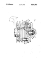
- FIGURE is a partial longitudinal cross sectional view of a fan drive mechanism made pursuant to the teachings of the present invention.
- a fan drive mechanism generally indicated by the numeral 10 includes a spindle 12 which is mounted to a stationary portion of the vehicle by a bracket 14.
- the spindle 12 is generally mounted in front of the vehicle engine and between the engine and the vehicle radiator so that operation of the cooling fan draws air through the radiator in the conventional manner.
- the engine cooling fan (not shown) is bolted to a fan plate 15 by bolts received in openings 16 in the fan plate 15.
- the fan plate 15 is mounted on the spindle 12 by bearings 18, 20.
- Each of the bearings 18, 20 includes an outer race 22 which is fixed to the fan plate 15, an inner race 24, which is mounted on the spindle 12, and ball bearings 26 interposed between the races 22, 24.
- a driving member generally indicated by the numeral 28 is rotatably mounted on the spindle 12 by bearings generally indicated by the numeral 30.
- the driving member 28 is provided with the conventional V-belt grooves 32 for connection with the vehicle engine so that the driving member 28 may be rotated thereby.
- the driving member 28 further includes a portion movable axially or a pressure plate generally indicated by the numeral 34 which is supported on circumferentially spaced pins 36 on the portion 38 of the driving member 28 which carries the V-belt grooves 32.
- the pressure plate 34 may also be considered to be a means engagable and disengagable from the fan plate.
- the pressure plate 34 carries friction material 40 for engagement with the conical engagement surface 42 defined on the fan plate 15 to thereby form a driving connection between the driving member 28 and the fan plate 15 when the drive mechanism effects a driving connection with the vehicle fan.
- Circumferentially spaced springs 44 between the portion 38 of the driving member 28 and the pressure plate 34 yieldably urge the pressure plate 34 into driving engagement with the fan plate 15.
- a sensor not shown
- the driving connection with the fan plate 15 is broken by moving the pressure plate 34 out of driving engagement with the engagement surface 42 by operation of a fluid pressure responsive means or fluid motor generally indicated by the numeral 46.
- the fluid motor 46 and pressure plate 34 comprise a disengagable drive means.
- Fluid motor 46 includes a circumferentially extending cylinder assembly generally indicated by the numeral 48.
- Cylinder assembly 48 is mounted on the spindle 12 and includes a face portion 50 which is engaged by the inner race 24 of the bearing 18 and an opposite face 52 which is engaged by a shoulder 54 on the spindle 12, thereby locking the cylinder assembly 48 on the spindle 12.
- a piston assembly 56 is slidably mounted on larger diameter portion 58 of the spindle 12 and is slidingly received within the cylinder assembly 48.
- the pressure plate 34 is rotatably supported on the piston 56 by a bearing generally indicated by the numeral 60.
- the spindle 12 terminates in a threaded end 62.
- a stop nut generally indicated by the numeral 64 is threadedly received on the threaded end 62 and includes a circumferentially extending forward face 66 which abuts the inner race 24 of the bearing 20.
- the nut 64 is retained by a cotter pin 68 received through an opening in nut 64 and hole in shaft 12 end.
- a conical surface generally indicated by the numeral 70 tapers radially outwardly from the face 66.
- the conical surface 70 terminates in a radially projecting flange 72 that cooperates with axially extending portion 74 of fan plate 15 to at least partially protect the bearings 18, 20 from environmental contaminants.
- springs 44 normally yieldably urge the pressure plate 34 into driving engagement with the fan plate 15 so that rotation of the driven member 28 by the vehicle engine is transmitted to the fan plate 15 to thereby rotate the engine cooling fan.
- the sensor senses that the cooling effect of the fan is no longer necessary, the sensor communicates air pressure from the vehicle air brake system through the passages 76 within the spindle 12 into the chamber defined between the cylinder 48 and the piston 56.
- Fluid pressure in the chamber urges the piston 56 to the left, viewing the FIGURE, thereby urging pressure plate 34 away from driving engagement with the fan plate 15, to break the driving connection therebetween to permit the fan plate 15 to freewheel on the bearings 18, 20, until the aforementioned pressure sensor senses that the cooling effect of the fan is again necessary, whereupon the chamber between the piston 56 and cylinder assembly 48 is vented to permit the springs 44 to again urge the pressure plate 34 into driving engagement with the fan plate 15.
- the bearings 18, 20 which rotatably support the fan plate 15 may ultimately fail. When this occurs, springs 44 tend to drive the pressure plate 34 and fan plate 15 to the right, viewing the FIGURE.
- the fan plate 15 was driven off the end of the spindle 12, while the fan plate 15 continued to rotate.
- the conical surface 70 catches the balls 26 and outer race 22 of the bearing 20.
- the conical surface 70 tapers such that the force transmitting balls of the bearing 22 are caught at some point on the axial length of the conical surface 70.
- the conical surface 70 frictionally engages the bearing parts to stop the fan plate 15 from rotating, while the tapered surface 70 controls the wobble of the plate 15 as it comes to the stop, thereby preventing it from deflecting into the radiator.
- the axial length of the surface 70 is sufficiently long that it limits movement of the plate 15 along the axis of the spindle 12 during failure of the bearings to an incremental amount longer than the maximum stroke of the piston 56.
- the maximum stroke of the piston 56 is also the maximum axial movement of the pressure plate 34. Accordingly, because an incremental additional axial movement of the plate 15 is permitted upon failure of the bearings, it can be assured that the plate 15 will be permitted to move out of driving engagement with the pressure plate 34. Accordingly, the braking effect of the friction between the conical surface 70 and the bearing parts is able to stop rotation of the fan plate 15.
Landscapes
- Engineering & Computer Science (AREA)
- General Engineering & Computer Science (AREA)
- Mechanical Engineering (AREA)
- Physics & Mathematics (AREA)
- Fluid Mechanics (AREA)
- Chemical & Material Sciences (AREA)
- Combustion & Propulsion (AREA)
- Structures Of Non-Positive Displacement Pumps (AREA)
- Power Steering Mechanism (AREA)
- Cold Air Circulating Systems And Constructional Details In Refrigerators (AREA)
- Vending Machines For Individual Products (AREA)
Priority Applications (9)
| Application Number | Priority Date | Filing Date | Title |
|---|---|---|---|
| US06/745,152 US4638900A (en) | 1985-06-17 | 1985-06-17 | Fan drive mechanism |
| JP61502021A JPH0711247B2 (ja) | 1985-06-17 | 1986-03-25 | ファン駆動機構 |
| EP86902604A EP0229074B1 (fr) | 1985-06-17 | 1986-03-25 | Mecanisme d'entrainement de ventilateurs |
| PCT/US1986/000605 WO1986007623A1 (fr) | 1985-06-17 | 1986-03-25 | Mecanisme d'entrainement de ventilateurs |
| DE8686902604T DE3663377D1 (en) | 1985-06-17 | 1986-03-25 | Fan drive mechanism |
| BR8606720A BR8606720A (pt) | 1985-06-17 | 1986-03-25 | Mecanismo acionador de ventilador |
| AU56697/86A AU577013B2 (en) | 1985-06-17 | 1986-03-25 | Fan drive mechanism |
| CA000508429A CA1324930C (fr) | 1985-06-17 | 1986-05-05 | Mecanisme d'entrainement de ventilateur |
| MX2521A MX163577B (es) | 1985-06-17 | 1986-05-16 | Mecanismo impulsor de ventilador |
Applications Claiming Priority (1)
| Application Number | Priority Date | Filing Date | Title |
|---|---|---|---|
| US06/745,152 US4638900A (en) | 1985-06-17 | 1985-06-17 | Fan drive mechanism |
Publications (1)
| Publication Number | Publication Date |
|---|---|
| US4638900A true US4638900A (en) | 1987-01-27 |
Family
ID=24995475
Family Applications (1)
| Application Number | Title | Priority Date | Filing Date |
|---|---|---|---|
| US06/745,152 Expired - Fee Related US4638900A (en) | 1985-06-17 | 1985-06-17 | Fan drive mechanism |
Country Status (9)
| Country | Link |
|---|---|
| US (1) | US4638900A (fr) |
| EP (1) | EP0229074B1 (fr) |
| JP (1) | JPH0711247B2 (fr) |
| AU (1) | AU577013B2 (fr) |
| BR (1) | BR8606720A (fr) |
| CA (1) | CA1324930C (fr) |
| DE (1) | DE3663377D1 (fr) |
| MX (1) | MX163577B (fr) |
| WO (1) | WO1986007623A1 (fr) |
Cited By (4)
| Publication number | Priority date | Publication date | Assignee | Title |
|---|---|---|---|---|
| US5215175A (en) * | 1991-12-16 | 1993-06-01 | Allied-Signal Inc. | Clutch drive mechanism |
| US20060081124A1 (en) * | 2004-10-19 | 2006-04-20 | Borgwarner Inc. | Single-piece air cylinder for a fluid coupling device |
| US20060081123A1 (en) * | 2004-10-19 | 2006-04-20 | Borgwarner Inc. | Single-piece electro-polished air cylinder for a fluid coupling device |
| US20120164002A1 (en) * | 2010-12-22 | 2012-06-28 | Kit Masters | Viscous two-speed clutch |
Families Citing this family (1)
| Publication number | Priority date | Publication date | Assignee | Title |
|---|---|---|---|---|
| US4830161A (en) * | 1987-09-25 | 1989-05-16 | Allied-Signal Inc. | Fan clutch |
Citations (11)
| Publication number | Priority date | Publication date | Assignee | Title |
|---|---|---|---|---|
| FR571180A (fr) * | 1923-09-12 | 1924-05-13 | Charles L Charley | Perfectionnements aux roues à disque plein pour automobiles ou autres véhicules de routes |
| US2890687A (en) * | 1958-09-29 | 1959-06-16 | Eugene E Richmond | Thermo hydraulic valve |
| US2906558A (en) * | 1955-06-24 | 1959-09-29 | Gen Motors Corp | Vehicle wheel fastening means |
| US3468570A (en) * | 1967-08-15 | 1969-09-23 | Lloyd L Mielke | Safety pivot connection |
| US3757914A (en) * | 1970-11-21 | 1973-09-11 | Dynair Ltd | Fan drives |
| US3985214A (en) * | 1974-12-04 | 1976-10-12 | The Bendix Corporation | Fan clutch drive |
| US4425993A (en) * | 1981-02-20 | 1984-01-17 | Horton Industries, Inc. | Fluid engaged spring released fan clutch having a modular mount for a spring engaged fluid released fan clutch |
| US4445606A (en) * | 1981-12-14 | 1984-05-01 | Warner Electric Brake & Clutch Company | Armature assembly for electromagnetic coupling |
| US4460079A (en) * | 1981-06-08 | 1984-07-17 | Horton Industries, Inc. | Modular unit for use with a fluid engaged spring released and a spring engaged fluid released fan clutch |
| US4483430A (en) * | 1983-03-09 | 1984-11-20 | The Bendix Corporation | Clutch drive |
| US4541516A (en) * | 1983-03-09 | 1985-09-17 | Allied Corporation | Clutch drive with antirotation spring |
Family Cites Families (6)
| Publication number | Priority date | Publication date | Assignee | Title |
|---|---|---|---|---|
| US2811378A (en) * | 1953-12-15 | 1957-10-29 | Kalista George | Heavy tension load safety swivel |
| US3708215A (en) * | 1968-11-14 | 1973-01-02 | Mechanical Tech Inc | Hybrid boost bearing assembly |
| US3782796A (en) * | 1972-12-18 | 1974-01-01 | Morgan Construction Co | Retaining means for a bearing assembly |
| CH594828A5 (fr) * | 1976-06-03 | 1978-01-31 | Bbc Brown Boveri & Cie | |
| US4148271A (en) * | 1978-03-20 | 1979-04-10 | General Motors Corporation | Incipient bearing failure indicator |
| GB1583822A (en) * | 1978-04-03 | 1981-02-04 | Evans Prod Co | Fluid actuatable fan clutch |
-
1985
- 1985-06-17 US US06/745,152 patent/US4638900A/en not_active Expired - Fee Related
-
1986
- 1986-03-25 EP EP86902604A patent/EP0229074B1/fr not_active Expired
- 1986-03-25 DE DE8686902604T patent/DE3663377D1/de not_active Expired
- 1986-03-25 JP JP61502021A patent/JPH0711247B2/ja not_active Expired - Lifetime
- 1986-03-25 AU AU56697/86A patent/AU577013B2/en not_active Ceased
- 1986-03-25 WO PCT/US1986/000605 patent/WO1986007623A1/fr active IP Right Grant
- 1986-03-25 BR BR8606720A patent/BR8606720A/pt not_active IP Right Cessation
- 1986-05-05 CA CA000508429A patent/CA1324930C/fr not_active Expired - Fee Related
- 1986-05-16 MX MX2521A patent/MX163577B/es unknown
Patent Citations (11)
| Publication number | Priority date | Publication date | Assignee | Title |
|---|---|---|---|---|
| FR571180A (fr) * | 1923-09-12 | 1924-05-13 | Charles L Charley | Perfectionnements aux roues à disque plein pour automobiles ou autres véhicules de routes |
| US2906558A (en) * | 1955-06-24 | 1959-09-29 | Gen Motors Corp | Vehicle wheel fastening means |
| US2890687A (en) * | 1958-09-29 | 1959-06-16 | Eugene E Richmond | Thermo hydraulic valve |
| US3468570A (en) * | 1967-08-15 | 1969-09-23 | Lloyd L Mielke | Safety pivot connection |
| US3757914A (en) * | 1970-11-21 | 1973-09-11 | Dynair Ltd | Fan drives |
| US3985214A (en) * | 1974-12-04 | 1976-10-12 | The Bendix Corporation | Fan clutch drive |
| US4425993A (en) * | 1981-02-20 | 1984-01-17 | Horton Industries, Inc. | Fluid engaged spring released fan clutch having a modular mount for a spring engaged fluid released fan clutch |
| US4460079A (en) * | 1981-06-08 | 1984-07-17 | Horton Industries, Inc. | Modular unit for use with a fluid engaged spring released and a spring engaged fluid released fan clutch |
| US4445606A (en) * | 1981-12-14 | 1984-05-01 | Warner Electric Brake & Clutch Company | Armature assembly for electromagnetic coupling |
| US4483430A (en) * | 1983-03-09 | 1984-11-20 | The Bendix Corporation | Clutch drive |
| US4541516A (en) * | 1983-03-09 | 1985-09-17 | Allied Corporation | Clutch drive with antirotation spring |
Cited By (8)
| Publication number | Priority date | Publication date | Assignee | Title |
|---|---|---|---|---|
| US5215175A (en) * | 1991-12-16 | 1993-06-01 | Allied-Signal Inc. | Clutch drive mechanism |
| WO1993012355A1 (fr) * | 1991-12-16 | 1993-06-24 | Allied-Signal Inc. | Mecanisme d'entrainement a griffes |
| US20060081124A1 (en) * | 2004-10-19 | 2006-04-20 | Borgwarner Inc. | Single-piece air cylinder for a fluid coupling device |
| US20060081123A1 (en) * | 2004-10-19 | 2006-04-20 | Borgwarner Inc. | Single-piece electro-polished air cylinder for a fluid coupling device |
| US7137333B2 (en) * | 2004-10-19 | 2006-11-21 | Borgwarner Inc. | Single-piece electro-polished air cylinder for a fluid coupling device |
| US7430956B2 (en) * | 2004-10-19 | 2008-10-07 | Borgwarner Inc. | Single-piece air cylinder for a fluid coupling device |
| US20120164002A1 (en) * | 2010-12-22 | 2012-06-28 | Kit Masters | Viscous two-speed clutch |
| US8863929B2 (en) * | 2010-12-22 | 2014-10-21 | Kit Masters | Viscous two-speed clutch |
Also Published As
| Publication number | Publication date |
|---|---|
| MX163577B (es) | 1992-06-03 |
| DE3663377D1 (en) | 1989-06-22 |
| JPH0711247B2 (ja) | 1995-02-08 |
| WO1986007623A1 (fr) | 1986-12-31 |
| JPS63500816A (ja) | 1988-03-24 |
| EP0229074A1 (fr) | 1987-07-22 |
| BR8606720A (pt) | 1987-08-11 |
| CA1324930C (fr) | 1993-12-07 |
| AU5669786A (en) | 1987-01-13 |
| AU577013B2 (en) | 1988-09-08 |
| EP0229074B1 (fr) | 1989-05-17 |
Similar Documents
| Publication | Publication Date | Title |
|---|---|---|
| US3985214A (en) | Fan clutch drive | |
| US6938735B1 (en) | Electromechanical wheel brake device | |
| CA1174488A (fr) | Protecteur contre les exces de couple sur vis-meres | |
| EP1602845B1 (fr) | Mécanisme de desacoupplement | |
| EP0119137B1 (fr) | Transmission d'embrayage | |
| EP0118371B1 (fr) | Transmission d'embrayage avec ressort anti-rotations | |
| CA1082060A (fr) | Commande de ventilateur pour vehicule automobile | |
| US4638900A (en) | Fan drive mechanism | |
| WO2019163595A1 (fr) | Frein électrique et dispositif de commande | |
| US5215175A (en) | Clutch drive mechanism | |
| US4946014A (en) | Retarder | |
| US3621958A (en) | Bidirectional no-back unit for ball screw utilizing roller cams | |
| EP0284388A2 (fr) | Assemblage de compresseur entraîné par un embrayage | |
| JPS59166720A (ja) | クラツチ駆動装置 | |
| US4291791A (en) | Free wheel hub mechanism | |
| EP0331362B1 (fr) | Dispositif d'engagement retardé d'une transmission | |
| JPS5840252Y2 (ja) | クラッチ付ファン駆動装置 | |
| KR102211023B1 (ko) | 에어 디스크 브레이크의 캘리퍼 위치 검출 장치 | |
| KR960012616B1 (ko) | 산업용차량의 브레이크장치 | |
| KR200144451Y1 (ko) | 자동차 클러치의 디스크 교환 경보장치 | |
| GB2023750A (en) | Engine fan clutch | |
| KR19980017509A (ko) | 클러치 디스크 교환시기 디스플레이 장치 | |
| KR19980054148A (ko) | 엔진 브레이크 장치 | |
| KR19980054155A (ko) | 엔진 브레이크 장치 | |
| KR19990026443U (ko) | 차량의 엔진시동 꺼짐 방지장치 |
Legal Events
| Date | Code | Title | Description |
|---|---|---|---|
| AS | Assignment |
Owner name: ALLIED CORPORATION COLUMBIA ROAD AND PARK AVE., MO Free format text: ASSIGNMENT OF ASSIGNORS INTEREST.;ASSIGNORS:DEEM, BRIAN C.;KEMP, JACK A.;REEL/FRAME:004417/0297 Effective date: 19850607 Owner name: ALLIED CORPORATION, A CORP OF NY,NEW JERSEY Free format text: ASSIGNMENT OF ASSIGNORS INTEREST;ASSIGNORS:DEEM, BRIAN C.;KEMP, JACK A.;REEL/FRAME:004417/0297 Effective date: 19850607 |
|
| FEPP | Fee payment procedure |
Free format text: PAYOR NUMBER ASSIGNED (ORIGINAL EVENT CODE: ASPN); ENTITY STATUS OF PATENT OWNER: LARGE ENTITY |
|
| FPAY | Fee payment |
Year of fee payment: 4 |
|
| FPAY | Fee payment |
Year of fee payment: 8 |
|
| REMI | Maintenance fee reminder mailed | ||
| LAPS | Lapse for failure to pay maintenance fees | ||
| FP | Lapsed due to failure to pay maintenance fee |
Effective date: 19990127 |
|
| STCH | Information on status: patent discontinuation |
Free format text: PATENT EXPIRED DUE TO NONPAYMENT OF MAINTENANCE FEES UNDER 37 CFR 1.362 |