US4635952A - Steering knuckle and kingpin assembly - Google Patents
Steering knuckle and kingpin assembly Download PDFInfo
- Publication number
- US4635952A US4635952A US06/731,557 US73155785A US4635952A US 4635952 A US4635952 A US 4635952A US 73155785 A US73155785 A US 73155785A US 4635952 A US4635952 A US 4635952A
- Authority
- US
- United States
- Prior art keywords
- kingpin
- bushing
- end portion
- peripheral surface
- yoke
- Prior art date
- Legal status (The legal status is an assumption and is not a legal conclusion. Google has not performed a legal analysis and makes no representation as to the accuracy of the status listed.)
- Expired - Fee Related
Links
- 230000002093 peripheral effect Effects 0.000 claims abstract description 43
- 238000002156 mixing Methods 0.000 claims abstract description 9
- 230000003247 decreasing effect Effects 0.000 claims 3
- 230000004048 modification Effects 0.000 claims 1
- 238000012986 modification Methods 0.000 claims 1
- 239000004519 grease Substances 0.000 description 10
- 230000000694 effects Effects 0.000 description 8
- 230000000712 assembly Effects 0.000 description 6
- 238000000429 assembly Methods 0.000 description 6
- 230000005489 elastic deformation Effects 0.000 description 5
- 239000000314 lubricant Substances 0.000 description 5
- 230000003068 static effect Effects 0.000 description 5
- 230000001050 lubricating effect Effects 0.000 description 3
- 230000007797 corrosion Effects 0.000 description 2
- 238000005260 corrosion Methods 0.000 description 2
- 230000006866 deterioration Effects 0.000 description 2
- 239000000463 material Substances 0.000 description 2
- 239000002184 metal Substances 0.000 description 2
- 239000000203 mixture Substances 0.000 description 2
- 238000005299 abrasion Methods 0.000 description 1
- 230000007423 decrease Effects 0.000 description 1
- 230000001419 dependent effect Effects 0.000 description 1
- 238000006073 displacement reaction Methods 0.000 description 1
- 238000005242 forging Methods 0.000 description 1
- 238000007373 indentation Methods 0.000 description 1
- 230000000977 initiatory effect Effects 0.000 description 1
- 230000035939 shock Effects 0.000 description 1
- 125000006850 spacer group Chemical group 0.000 description 1
Images


Classifications
-
- B—PERFORMING OPERATIONS; TRANSPORTING
- B62—LAND VEHICLES FOR TRAVELLING OTHERWISE THAN ON RAILS
- B62D—MOTOR VEHICLES; TRAILERS
- B62D7/00—Steering linkage; Stub axles or their mountings
- B62D7/18—Steering knuckles; King pins
Definitions
- the present invention relates to steering knuckle and kingpin assemblies in general, and more particularly to steering kingpin and knuckle assemblies for heavy motor vehicles.
- Steering knuckle and kingpin assemblies used in heavy motor vehicles such as trucks and the like, consist generally of a circularly cylindrical kingpin fastened through a substantially vertical bore in opposite ends of the vehicle front axle, and of a wheel spindle knuckle pivotable relative to the kingpin.
- the knuckle has an integral upper yoke and an integral lower yoke that straddle the axle end and pivot relative to the kingpin ends projecting above and below the axle.
- Appropriate bushings are fixedly fitted in the yoke bores, and the bearing surfaces in engagement, namely the internal cylindrical surface of the yoke bushing and the corresponding cylindrical peripheral surface of the kingpin ends, are subjected to substantial and variable loads, vibrations and shock, which eventually cause excessive wear, requiring replacement of the bushings, or of the kingpin, or both, replacement kingpins and bushings being generally marketed in the form of a complete kit or set. It is not uncommon to replace heavy truck steering knuckle and kingpin assemblies several times during the useful life of the vehicle.
- the kingpin is subjected to torque force in a substantially vertical plane through the intermediary of the knuckle yokes and bushings.
- the forces applied to the kingpin ends in opposite directions tend to cause engagement of a localized area of the peripheral surface at the top of the upper end portion of the kingpin with a corresponding localized area of the inner surface of the upper yoke bushing, and of a localized area of the surface of the bottom of the kingpin lower portion with a corresponding localized area of the inner surface of the lower yoke bushing.
- the bearing surfaces in mutual contact are not the designed cylindrical bearing surfaces of the kingpin ends and yoke bushings as, under load, there is only point contact or line contact between the bearing surfaces causing excessive compressive stress.
- the bearing surfaces are generally not of equal lengths.
- the edge of the kingpin ends may project beyond the end of the shackle yoke bushings or, alternatively, the edge of the bushings may project beyond the kingpin ends.
- the edge of the bearing member in engagement with the surface of the other bearing member causes an indentation of the surface of the other bearing member, and further elastic or plastic deformation of both members at the line of contact, thus adding a stress riser at the point or line of maximum loading of the bearing surface, with accompanying failure and piercing of the lubricant film, in turn causing rapid deterioration of the bearing surfaces and propagation of wear from abrasion and from contact corrosion.
- the principal object of the present invention is to provide a structure for a motor vehicle steering knuckle and kingpin assembly which utilizes a greater bearing surface area in engagement between the kingpin peripheral surface and the knuckle bushing internal surface, such as to move uniformly distribute loads and stress on the bearing surfaces in engagement and reduce the pressure exerted on the lubricant film between the bearing surfaces.
- FIG. 1 is a schematic illustration of an example of structure for a steering knuckle and kingpin assembly according to the prior art
- FIGS. 2 and 3 are views similar to FIG. 1, at an enlarged scale and in a grossly exaggerated manner to illustrate the inconveniences of steering knuckle and kingpin assemblies according to the prior art;
- FIGS. 3(a) and 3(b) are partial views of respectively a kingpin end and a corresponding knuckle yoke bushing, according to the structure of FIGS. 1-3, and illustrating the wear pattern thereon;
- FIGS. 4 and 5 are views similar to FIG. 2 and FIG. 3, respectively, and schematically illustrating an example of structure according to the present invention
- FIGS. 6 and 7 are views similar to FIG. 4 and FIG. 5, respectively, but illustrating another example of structure according to the present invention.
- FIGS. 8 and 9 are views similar to FIGS. 6 and 7, respectively, and illustrating a further example of structure according to the present invention.
- FIGS. 10 and 11 are views similar to FIG. 8 and FIG. 9, respectively, and illustrating another example of structure according to the present invention.
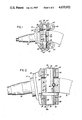
- a steering knuckle assembly 10 comprising a kingpin 12 mounted in a bore 14 in opposite ends of the rigid front axle or beam 16 of a motor vehicle, not shown, such as a heavy duty truck for example.
- the kingpin 12 is mounted through the bore 14 in the front axle or beam 16 at a slight angle to the vertical by means of a tapered lock pin 18 pressed through a tapered channel 20 through the axle or beam 16 and a corresponding straight notch 22 formed on the periphery of the kingpin 12. In this manner the kingpin 12 is held in the bore 14 against rotation and against vertical displacement along its longitudinal axis.
- a wheel spindle knuckle 24 is pivotally mounted relative to the kingpin 12 by way of two integral upper and lower yoke members 26 and 28, the upper yoke member 26 having a bore 30 accepting the upper end portion 32 of the kingpin 12, while the lower yoke member 28 of the wheel spindle knuckle 24 is similarly provided with a bore 34 surrounding the kingpin lower end portion 36.
- the upper end portion 32 of the kingpin 12, the lower end portion 36 of the kingpin 12 and the intermediate portion 38 are circularly cylindrical and usually of equal diameters.
- a bearing or bushing 44 is disposed in the upper yoke bore 30 for pivotably supporting the upper yoke member 26 around the kingpin upper end portion 32, and a similar bearing or bushing 44 is disposed in the lower yoke bore 34 between the bore surface and the lower end portion 36 of the kingpin 12.
- the peripheral surface 46 of each bushing 44 is circularly cylindrical such as to fit in the bore 30 or 36, and the internal surface 48 of each bushing 44 is circularly cylindrical corresponding to the circularly cylindrical periphery of the end portions 32 and 36 of the kingpin 12.
- Two wheel spindle knuckles 24, one on each end of the axle or beam 16, are coupled for simultaneous pivoting by an appropriate tie rod, not shown, generally provided with a ball and socket joint at each end, the ball, for example, having a stud fastened through an appropriate opening 50 in one of the yoke members, while another tie rod displaced by the steering mechanism of the vehicle, not shown, is attached at its end by way of a stud fastened through another opening 50 disposed in the other yoke member.
- the upper and lower yoke members 26 and 28 are integral parts of a single-piece forging, for example, and they form a generally U-shaped member supporting the spindle 52 of a steerable road wheel, not shown.
- a plurality of annular spacers shims 54 are mounted around the kingpin 12 where it projects on the top of the axle or beam 16 to provide appropriate clearance between the upper yoke member 26 and the axle or beam 16, while an annular thrust bearing 56 is disposed around the kingpin 12 where it projects below the axle or beam 16, the thrust bearing 56 transmitting the load from the axle or beam 16 to the lower yoke portion 28.
- the upper end of the upper yoke bore 30 is closed by a cap 58, provided at its center with a one-way check valve 60 and fastened on the edge of the upper yoke member 26 by means of bolts, such as bolts 62.
- the end of the lower yoke bore 34 is similarly closed by an end cap 58 also provided with a one-way check valve 60.
- the check valves 60 permit to observe visually the escape of lubricant introduced through grease fittings, not shown, permitting to lubricate the kingpin end portions 32 and 36 and the bearing surface of the bushings 44. When lubricant is observed to flow through the check valves 60, it is an indication that the knuckle-kingpin assembly has been fully lubricated.
- the check valves 60 are omitted and replaced by grease fittings through which lubricant is inserted into the knuckle-kingpin assembly.
- annular clearance space 64 normally exists between the cylindrical peripheral surface 66 of the kingpin upper end 32 and the internal cylindrical surface 48 of the upper yoke bushing 44, and a similar annular clearance 68 exists between the cylindrical peripheral surface 70 of the kingpin lower end 36 and the cylindrical internal surface 48 of the lower yoke bushing 46.
- the radial clearance 64 or 68 which conventionally is in the range of 0.001 to 0.003 in.
- FIG. 1 (0.025-0.762 mm), and which is shown grossly exaggerated in the drawing, allows the steering knuckle 24 to pivot relative to the kingpin 12 without binding, and permit the establishment of a lubricating film, such as a grease film, between the bearing surfaces.
- a lubricating film such as a grease film
- FIG. 2 illustrates the steering kingpin and knuckle assembly 10, assuming no load being applied to the kingpin end portions 32 and 36 by the knuckle 24, such that the bearing surfaces of the kingpin end portions 32 and 36 and of the yoke bushings 44 are disposed substantially concentric to one another, with the clearance annular spaces 64 and 68 of equal constant thickness between the peripheral surface 66 of the kingpin upper end portion 32 and the internal surface 48 of the upper yoke bushing 44 and between the peripheral surface 70 of the kingpin lower end portion 36 and the internal surface 48 of the lower yoke bushing 44.
- FIG. 3 Under static load, FIG. 3, with a portion of the weight of the vehicle being applied to the ground through the road wheel, not shown, mounted on the spindle 52, a twisting force is applied on the steering knuckle 24 from the wheel spindle 52 in the direction of the arrow.
- the twisting force causes surface engagement between a narrow surface area at the top edge 78 of the peripheral surface 66 of the kingpin upper end portion 32 and a corresponding area at or proximate the top edge of the internal surface 48 of the upper yoke bushing 44, as designated at A.
- the engagement between the respective surfaces is for all practical purpose point contact, that becomes a circular line engagement during steering, which results in expelling from between the bearing surfaces in engagement the film of lubricating grease and causes direct metal to metal contact.
- the clearance space becomes askew as shown at 64'.
- the lower annular clearance space 68 becomes askew, as shown at 68', and a point contact is established between the peripheral surface 70 at the bottom edge 80 of the lower kingpin end 36 and the corresponding internal surface 48 at the edge of the lower yoke bushing 44 as designated at B.
- the point contact areas carry the whole static load and, during pivoting of the steering knuckle 24 around the kingpin 12 in the course of steering the vehicle, the circular line contact areas continuously wear and abrade one another, such wear and abrading being further increased in the course of dynamic load variations in practical usage of the vehicle. Even while at rest, contact corrosion takes place between the surfaces in engagement.
- the stress force applied upon the kingpin 12 is applied principally at the extreme end of the kingpin end portions 32 and 36, which tends to bend the kingpin in a generally S-shape, the points A and B of application of the forces being diametrically opposed.
- the wear pattern as illustrated at 72, FIG. 3(a), and at 73, FIG. 3(b), for respectively the kingpin end and the bushing end edge, extend only over a small surface area of respectively the kingpin peripheral surface and the bushing internal surface, but nevertheless require that the components be replaced.
- the edge effect initiating the wear pattern of conventional heavy duty steering kingpin and knuckle assemblies is eliminated, according to the present invention, by providing the kingpin end portions 32 and 36 with an appropriate taper or frusto-conical shape, shown in a grossly exaggerated fashion at FIG. 4, which represents an improved structure for a steering kingpin and knuckle assembly in an unloaded condition.
- the end portions 32 and 36 of the kingpin 12 are therefore provided with peripheral tapered or frusto-conical surfaces 74 and 76 of a diameter larger at their junction with the kingpin main cylindrical portion 38 mounted in the bore 14 of the axle 16, and which progressively and linearly decreases to a smaller diameter proximate the extreme end edge 78 of the kingpin upper end portion 32 and 80 of the kingpin lower end portion 36.
- Such difference in diameters is very small and, for all practical purposes, amounts to a difference between the larger diameter and the smaller diameter of each kingpin end portions 32 and 36 in the range of 0.001 to 0.006 in (0.025 to 0.15 mm).
- the corresponding bushings 44 in the upper yoke bore 30 and lower yoke bore 34 are provided with a circularly cylindrical internal surface 48, in the example of structure illustrated at FIG. 4, such that under normal static load, FIG. 5, the peripheral tapered surface, or frusto-conical surface 74, of the kingpin upper end portion 32 tends to engage the upper yoke bushing internal surface 48 in line contact over the whole length of the kingpin end portion 32 and over the whole length of the bushing internal surface 48, as shown, an appropriate substantially wedge-shaped grease film being substantially uniformly distributed between the bearing surfaces.
- the kingpin end portions 32 and 36 may be left circularly cylindrical, FIG. 6, and the yoke bushings 44 provided with tapered, or frusto-conical, internal surfaces 82.
- the larger diameter of the upper yoke bushing bore surface 82 is larger at its top than at its bottom, while the inner diameter of the bore surface 82 of the lower yoke bushing 44 is larger at its lower end than at its upper end, the difference in diameters being of the same order as the difference in diameters of the kingpin ends of the structure of FIGS. 4-5.
- both the kingpin end portions and the yoke bushing bores may be provided with opposite tapers.
- the degree of elastic deformation is dependent upon the modulus of elasticity of the material used for the components forming the bearing surfaces in mutual engagement.
- the present invention contemplates taking advantage of elastic deformation of the kingpin peripheral bearing surface and of the yoke bushing internal bearing surface to eliminate the wear edge effect of conventional steering knuckle yoke bushing and kingpin asssemblies and to increase the areas of bearing surfaces in engagement under normal load.
- the edge effect causes uneven wear of the internal surface 48 of the upper yoke and lower yoke bushings 44 or, in the alternative, of the kingpin upper end portion peripheral surface 66 and kingpin lower end portion peripheral surface 70 proximate their upper and lower edges, according to whether the edge of the kingpin end portions 32 and 36 is disposed beyond or short of the corresponding end edge of the corresponding bushing 44.
- the edge of the kingpin upper end portion 32 in point contact at point A with the internal surface 48 of the bushing eventually forms an annular groove in the portion of the internal surface 48 of the upper yoke bushing 44 proximate the top edge thereof, resulting from continuous rubbing of the relatively sharp edge 78 of the kingpin end portion 32 against the internal surface 48 of the bushing. If the kingpin end portion 32 projects beyond the edge of the upper yoke bushing 44, the edge of the bushing wears a groove in the peripheral surface 66 of the kingpin upper end portion 32, proximate its top edge.
- edge effect also takes place, in a diametrically opposed location, with respect to the edge 80 of the kingpin lower end portion 36 and corresponding lower yoke bushing 44.
- the kingpin end portions 32 and 36 and the bushings 44 may be routinely provided with smoothly blending radiused edges, notwithstanding the relative lengths of the bearing members. It will be further appreciated that, although referred to as being radiused edges, the progressively and smoothly blending end edges 79 and 81 of the kingpin 12 are preferably in the form of a truncated ellipsoid or paraboloid rather than in the form of a spherical zone, such that the curved surface blends progressively into the cylindrical surface of the kingpin end portions 32 and 36 with practically no line of demarcation.
- the progressively and smoothly blending end edges 79' and 81' of the bushings 44 are preferably formed as reciprocal, or inverse, ellipsoidal or paraboloidal surfaces rather than formed as a reciprocal, or inverse, spherical zone surface, such that the curved surface blends progressively into the cylindrical internal surface of the bushings 44 with practically no line of demarcation.
- the edge effect is also eliminated by the structure illustrated at FIG. 8, as a result of providing the upper and lower kingpin end portions 32 and 36 with a particular geometry, shown in grossly exaggerated manner for illustrative purpose.
- the kingpin upper end portion 32 and lower end portion 36 instead of being absolutely circularly cylindrical, are slightly barrel-shaped, or spherically shaped, the radius of the sphere being very large such as a radius of several meters for example, with the result that the middle area of the kingpin upper and lower end portions 32 and 36, as shown at 84 and 86, respectively, is capable of static linear engagement with a corresponding area 88 of the internal cylindrical surface 48 of respectively the upper yoke and lower yoke bushing 44, with an appropriate grease film interposed between the bearing surfaces, and that there is a wedge-shaped annular clearance space, as shown respectively at 90 and 92, beyond the kingpin end portions bulging areas 84 and 86.
- the large radius spherical surfaces of the kingpin upper end portion 32 and lower end portion 36 tend to pivot in a vertical plane axis relative to their respective upper and lower yoke bushings 44, the relative wedge-shaped clearance spaces 90 and 92 preventing nevertheless edge engagement between the kingpin end portion edges 78 and 80, even if provided with a bevel, as shown, and the internal cylindical surface 48 of the bushings 44, proximate their end edge, in the event that the kingpin end edges are disposed lower than the bushing edges, and vice-versa in the event that the kingpin upper and lower end portions 32 and 36 have their edge disposed beyond the end edges of the corresponding bushings 44.
Landscapes
- Engineering & Computer Science (AREA)
- Chemical & Material Sciences (AREA)
- Combustion & Propulsion (AREA)
- Transportation (AREA)
- Mechanical Engineering (AREA)
- Steering-Linkage Mechanisms And Four-Wheel Steering (AREA)
- Vehicle Body Suspensions (AREA)
Priority Applications (6)
| Application Number | Priority Date | Filing Date | Title |
|---|---|---|---|
| US06/731,557 US4635952A (en) | 1985-05-07 | 1985-05-07 | Steering knuckle and kingpin assembly |
| EP86200760A EP0201965B1 (fr) | 1985-05-07 | 1986-05-02 | Articulation de direction et ensemble de fusée |
| DE8686200760T DE3673557D1 (de) | 1985-05-07 | 1986-05-02 | Lenkungsgelenk und koenigzapfen-zusammenbau. |
| BR8602029A BR8602029A (pt) | 1985-05-07 | 1986-05-06 | Aperfeicoamento em conjunto de braco de ponta de eixo e pino-mestre de direcao |
| JP61103706A JPH0775989B2 (ja) | 1985-05-07 | 1986-05-06 | ナツクル・キングピン操向構造体 |
| CA000508524A CA1247671A (fr) | 1985-05-07 | 1986-05-06 | Ensemble de rotule et fusee de direction |
Applications Claiming Priority (1)
| Application Number | Priority Date | Filing Date | Title |
|---|---|---|---|
| US06/731,557 US4635952A (en) | 1985-05-07 | 1985-05-07 | Steering knuckle and kingpin assembly |
Publications (1)
| Publication Number | Publication Date |
|---|---|
| US4635952A true US4635952A (en) | 1987-01-13 |
Family
ID=24940025
Family Applications (1)
| Application Number | Title | Priority Date | Filing Date |
|---|---|---|---|
| US06/731,557 Expired - Fee Related US4635952A (en) | 1985-05-07 | 1985-05-07 | Steering knuckle and kingpin assembly |
Country Status (6)
| Country | Link |
|---|---|
| US (1) | US4635952A (fr) |
| EP (1) | EP0201965B1 (fr) |
| JP (1) | JPH0775989B2 (fr) |
| BR (1) | BR8602029A (fr) |
| CA (1) | CA1247671A (fr) |
| DE (1) | DE3673557D1 (fr) |
Cited By (19)
| Publication number | Priority date | Publication date | Assignee | Title |
|---|---|---|---|---|
| US4786114A (en) * | 1986-05-21 | 1988-11-22 | Bergische Achsenfabrik Fr. Kotz & Sohne | Stabilizing mechanism for a follower guide axle of a vehicle trailer |
| US4915530A (en) * | 1987-08-21 | 1990-04-10 | General Motors Corporation | Kingpin assembly |
| US5340137A (en) * | 1991-06-25 | 1994-08-23 | Carraro S.P.A. | Steering axle |
| US5709399A (en) * | 1996-06-05 | 1998-01-20 | Smith, Jr.; Joseph E. | Motor vehicle steering assembly |
| US6186525B1 (en) * | 1997-04-10 | 2001-02-13 | Volvo Lastvagnar Ab | Suspension for a non-driven steerable vehicle wheel |
| US6203038B1 (en) * | 1997-11-07 | 2001-03-20 | Wandfluh Automotive Ag | Vehicle steering mechanism |
| US20050242540A1 (en) * | 2003-02-03 | 2005-11-03 | Hendrickson Usa, Llc | Adjustable boss for steering knuckle and method of installing same |
| US20100052289A1 (en) * | 2008-08-26 | 2010-03-04 | 1708828 Ontario Ltd. O/A Horst Welding | Trailer with Four Wheel Steering and Independent Suspension |
| US7918003B2 (en) | 2007-10-31 | 2011-04-05 | Acciardo Jr Andrew T | Kingpin bushing installation tool |
| US8678406B1 (en) * | 2012-09-28 | 2014-03-25 | GM Global Technology Operations LLC | Isolation sleeve |
| US8764034B2 (en) | 2012-07-27 | 2014-07-01 | Roller Bearing Company Of America, Inc. | Steering axle assembly with self-lubricated bearings |
| US20140361505A1 (en) * | 2014-08-27 | 2014-12-11 | Caterpillar Inc. | Kingpin assembly for steering and suspension linkage assembly |
| US20150175201A1 (en) * | 2012-06-21 | 2015-06-25 | Scania Cv Ab | Steering spindle arrangement |
| US20190256134A1 (en) * | 2018-02-19 | 2019-08-22 | Dana Heavy Vehicle Systems Group, Llc | King-Pin Joint Assembly |
| US10527085B2 (en) * | 2018-01-30 | 2020-01-07 | Cnh Industrial America Llc | Shim for a work vehicle axle assembly |
| CN111152840A (zh) * | 2018-11-08 | 2020-05-15 | 乔治费歇尔金属成型科技(昆山)有限公司 | 转向节 |
| US20220041213A1 (en) * | 2020-08-04 | 2022-02-10 | Dana Italia S.R.L. | King pin assembly |
| US20230241914A1 (en) * | 2022-01-30 | 2023-08-03 | Shanghai Linghuo Trading Co., Ltd. | Split-type hard front axle and vehicle having same |
| US20230303164A1 (en) * | 2022-03-22 | 2023-09-28 | Shock Therapy Suspension, Inc. | Adjustable height pin for a tie rod |
Families Citing this family (2)
| Publication number | Priority date | Publication date | Assignee | Title |
|---|---|---|---|---|
| US6113118A (en) * | 1998-09-30 | 2000-09-05 | Dana Corporation | Closed cell foam insert for a king pin/knuckle arm assembly |
| CN112032201B (zh) * | 2020-09-01 | 2022-05-03 | 中国重汽集团济南动力有限公司 | 一种主销衬套动力润滑结构 |
Citations (9)
| Publication number | Priority date | Publication date | Assignee | Title |
|---|---|---|---|---|
| US2806712A (en) * | 1955-01-31 | 1957-09-17 | Herbert T Cottrell | Steering gear for knee action suspensions in motor vehicles |
| US3441288A (en) * | 1967-04-27 | 1969-04-29 | Rockwell Standard Co | Steering knuckle sealing means |
| US3542392A (en) * | 1968-10-14 | 1970-11-24 | Rockwell Standard Co | Steering mechanism |
| US3549166A (en) * | 1968-07-18 | 1970-12-22 | Ford Motor Co | Vibration damper and preloader bearing assembly |
| US3801124A (en) * | 1972-10-13 | 1974-04-02 | Dayton Walther Corp | Knuckle assembly |
| US3861705A (en) * | 1970-11-11 | 1975-01-21 | Daimler Benz Ag | Shifting gear for the steering system of vehicle wheels |
| US4076345A (en) * | 1976-09-01 | 1978-02-28 | Caterpillar Tractor Co. | Sealed joint construction |
| US4229017A (en) * | 1978-09-29 | 1980-10-21 | Ford Motor Company | King pin assembly |
| US4286799A (en) * | 1979-09-18 | 1981-09-01 | Rockwell International Corporation | Kingpin assembly and method for making same |
Family Cites Families (2)
| Publication number | Priority date | Publication date | Assignee | Title |
|---|---|---|---|---|
| GB255290A (en) * | 1925-11-17 | 1926-07-22 | Guido Fornaca | An improved front wheel suspension for motor driven vehicles |
| GB1097273A (en) * | 1965-03-30 | 1968-01-03 | Cam Gears Clevedon Ltd | Improvements in combined journal and thrust bearing assemblies |
-
1985
- 1985-05-07 US US06/731,557 patent/US4635952A/en not_active Expired - Fee Related
-
1986
- 1986-05-02 EP EP86200760A patent/EP0201965B1/fr not_active Expired
- 1986-05-02 DE DE8686200760T patent/DE3673557D1/de not_active Expired - Fee Related
- 1986-05-06 CA CA000508524A patent/CA1247671A/fr not_active Expired
- 1986-05-06 JP JP61103706A patent/JPH0775989B2/ja not_active Expired - Lifetime
- 1986-05-06 BR BR8602029A patent/BR8602029A/pt not_active IP Right Cessation
Patent Citations (9)
| Publication number | Priority date | Publication date | Assignee | Title |
|---|---|---|---|---|
| US2806712A (en) * | 1955-01-31 | 1957-09-17 | Herbert T Cottrell | Steering gear for knee action suspensions in motor vehicles |
| US3441288A (en) * | 1967-04-27 | 1969-04-29 | Rockwell Standard Co | Steering knuckle sealing means |
| US3549166A (en) * | 1968-07-18 | 1970-12-22 | Ford Motor Co | Vibration damper and preloader bearing assembly |
| US3542392A (en) * | 1968-10-14 | 1970-11-24 | Rockwell Standard Co | Steering mechanism |
| US3861705A (en) * | 1970-11-11 | 1975-01-21 | Daimler Benz Ag | Shifting gear for the steering system of vehicle wheels |
| US3801124A (en) * | 1972-10-13 | 1974-04-02 | Dayton Walther Corp | Knuckle assembly |
| US4076345A (en) * | 1976-09-01 | 1978-02-28 | Caterpillar Tractor Co. | Sealed joint construction |
| US4229017A (en) * | 1978-09-29 | 1980-10-21 | Ford Motor Company | King pin assembly |
| US4286799A (en) * | 1979-09-18 | 1981-09-01 | Rockwell International Corporation | Kingpin assembly and method for making same |
Cited By (25)
| Publication number | Priority date | Publication date | Assignee | Title |
|---|---|---|---|---|
| US4786114A (en) * | 1986-05-21 | 1988-11-22 | Bergische Achsenfabrik Fr. Kotz & Sohne | Stabilizing mechanism for a follower guide axle of a vehicle trailer |
| US4915530A (en) * | 1987-08-21 | 1990-04-10 | General Motors Corporation | Kingpin assembly |
| US5340137A (en) * | 1991-06-25 | 1994-08-23 | Carraro S.P.A. | Steering axle |
| US5709399A (en) * | 1996-06-05 | 1998-01-20 | Smith, Jr.; Joseph E. | Motor vehicle steering assembly |
| US6186525B1 (en) * | 1997-04-10 | 2001-02-13 | Volvo Lastvagnar Ab | Suspension for a non-driven steerable vehicle wheel |
| US6203038B1 (en) * | 1997-11-07 | 2001-03-20 | Wandfluh Automotive Ag | Vehicle steering mechanism |
| US20050242540A1 (en) * | 2003-02-03 | 2005-11-03 | Hendrickson Usa, Llc | Adjustable boss for steering knuckle and method of installing same |
| US7530583B2 (en) * | 2003-02-03 | 2009-05-12 | Hendrickson Usa, L.L.C. | Adjustable boss for steering knuckle and method of installing same |
| US7918003B2 (en) | 2007-10-31 | 2011-04-05 | Acciardo Jr Andrew T | Kingpin bushing installation tool |
| US20100052289A1 (en) * | 2008-08-26 | 2010-03-04 | 1708828 Ontario Ltd. O/A Horst Welding | Trailer with Four Wheel Steering and Independent Suspension |
| US7874571B2 (en) | 2008-08-26 | 2011-01-25 | 1708828 Ontario Ltd. | Trailer with four wheel steering and independent suspension |
| US9211908B2 (en) * | 2012-06-21 | 2015-12-15 | Scania Cv Ab | Steering spindle arrangement |
| US20150175201A1 (en) * | 2012-06-21 | 2015-06-25 | Scania Cv Ab | Steering spindle arrangement |
| US8764034B2 (en) | 2012-07-27 | 2014-07-01 | Roller Bearing Company Of America, Inc. | Steering axle assembly with self-lubricated bearings |
| US8678406B1 (en) * | 2012-09-28 | 2014-03-25 | GM Global Technology Operations LLC | Isolation sleeve |
| US20140361505A1 (en) * | 2014-08-27 | 2014-12-11 | Caterpillar Inc. | Kingpin assembly for steering and suspension linkage assembly |
| US10527085B2 (en) * | 2018-01-30 | 2020-01-07 | Cnh Industrial America Llc | Shim for a work vehicle axle assembly |
| US20190256134A1 (en) * | 2018-02-19 | 2019-08-22 | Dana Heavy Vehicle Systems Group, Llc | King-Pin Joint Assembly |
| US10793189B2 (en) * | 2018-02-19 | 2020-10-06 | Dana Heavy Vehicle Systems Group, Llc | King-pin joint assembly |
| CN111152840A (zh) * | 2018-11-08 | 2020-05-15 | 乔治费歇尔金属成型科技(昆山)有限公司 | 转向节 |
| US20220041213A1 (en) * | 2020-08-04 | 2022-02-10 | Dana Italia S.R.L. | King pin assembly |
| US20230241914A1 (en) * | 2022-01-30 | 2023-08-03 | Shanghai Linghuo Trading Co., Ltd. | Split-type hard front axle and vehicle having same |
| US11731457B1 (en) * | 2022-01-30 | 2023-08-22 | Shanghai Linghuo Trading Co., Ltd. | Split-type hard front axle and vehicle having same |
| US20230303164A1 (en) * | 2022-03-22 | 2023-09-28 | Shock Therapy Suspension, Inc. | Adjustable height pin for a tie rod |
| US12017718B2 (en) * | 2022-03-22 | 2024-06-25 | Shock Therapy Suspension, Inc. | Adjustable height pin for a tie rod |
Also Published As
| Publication number | Publication date |
|---|---|
| EP0201965B1 (fr) | 1990-08-22 |
| JPS61257369A (ja) | 1986-11-14 |
| CA1247671A (fr) | 1988-12-28 |
| EP0201965A2 (fr) | 1986-11-20 |
| EP0201965A3 (en) | 1988-07-20 |
| DE3673557D1 (de) | 1990-09-27 |
| JPH0775989B2 (ja) | 1995-08-16 |
| BR8602029A (pt) | 1987-01-06 |
Similar Documents
| Publication | Publication Date | Title |
|---|---|---|
| US4635952A (en) | Steering knuckle and kingpin assembly | |
| US4690418A (en) | Steering knuckle and kingpin assembly | |
| US3007728A (en) | Joint structures and jointed suspension means | |
| US7837407B2 (en) | Cone adaptor for ball joint studs, tie rods, sway bar links and the like | |
| DE4211897C2 (de) | Kugelgelenk für Teile der Lenkung oder Radaufhängung von Kraftfahrzeugen | |
| EP0026864B1 (fr) | Joint à rotule | |
| US2827303A (en) | Vehicle suspension and pivot assembly therefor | |
| US10415632B2 (en) | Bearing for vehicle suspension | |
| US4259027A (en) | Constant torque ball joint | |
| US4907814A (en) | Self-adjusting bearing | |
| US20070273119A1 (en) | Steering arm | |
| US3375028A (en) | Ball joint for tie rod or the like | |
| US5350183A (en) | Steerable axle assembly with preloaded kingpin drawkeys | |
| US3135540A (en) | Articulated dual stud linkage joint | |
| US2108814A (en) | Joint construction | |
| US3147026A (en) | Stamped steering knuckles and brake backing plate weldment | |
| US2924469A (en) | Ball joint for independent steerable wheel suspensions | |
| US3361458A (en) | Double wedge eccentric ball joint | |
| US2464492A (en) | Self-aligning bearing | |
| US3169783A (en) | Drawbar hitch assembly | |
| US2857190A (en) | Compression-loaded ball joint | |
| EP0684404B1 (fr) | Agencement d'articulation pour tiges de réaction | |
| US3005647A (en) | Ball joint | |
| US2160862A (en) | Vehicle suspension | |
| US3352583A (en) | Joint for steering linkage and the like |
Legal Events
| Date | Code | Title | Description |
|---|---|---|---|
| AS | Assignment |
Owner name: V. W. KAISER ENGINEERING, INC., 8642 GLEASON ST., Free format text: ASSIGNMENT OF ASSIGNORS INTEREST.;ASSIGNOR:SMITH, JOSEPH E.;REEL/FRAME:004402/0526 Effective date: 19850403 |
|
| FEPP | Fee payment procedure |
Free format text: PAYOR NUMBER ASSIGNED (ORIGINAL EVENT CODE: ASPN); ENTITY STATUS OF PATENT OWNER: SMALL ENTITY |
|
| FPAY | Fee payment |
Year of fee payment: 4 |
|
| FPAY | Fee payment |
Year of fee payment: 8 |
|
| FEPP | Fee payment procedure |
Free format text: PAYER NUMBER DE-ASSIGNED (ORIGINAL EVENT CODE: RMPN); ENTITY STATUS OF PATENT OWNER: SMALL ENTITY Free format text: PAYOR NUMBER ASSIGNED (ORIGINAL EVENT CODE: ASPN); ENTITY STATUS OF PATENT OWNER: SMALL ENTITY |
|
| REMI | Maintenance fee reminder mailed | ||
| LAPS | Lapse for failure to pay maintenance fees | ||
| FP | Lapsed due to failure to pay maintenance fee |
Effective date: 19990113 |
|
| STCH | Information on status: patent discontinuation |
Free format text: PATENT EXPIRED DUE TO NONPAYMENT OF MAINTENANCE FEES UNDER 37 CFR 1.362 |