US463572A - Cabinet-organ - Google Patents
Cabinet-organ Download PDFInfo
- Publication number
- US463572A US463572A US463572DA US463572A US 463572 A US463572 A US 463572A US 463572D A US463572D A US 463572DA US 463572 A US463572 A US 463572A
- Authority
- US
- United States
- Prior art keywords
- bellows
- reed
- chamber
- reeds
- action
- Prior art date
- Legal status (The legal status is an assumption and is not a legal conclusion. Google has not performed a legal analysis and makes no representation as to the accuracy of the status listed.)
- Expired - Lifetime
Links
- 235000014676 Phragmites communis Nutrition 0.000 description 48
- 230000009471 action Effects 0.000 description 47
- 244000273256 Phragmites communis Species 0.000 description 44
- 210000000056 organ Anatomy 0.000 description 17
- 238000005192 partition Methods 0.000 description 13
- 238000010276 construction Methods 0.000 description 10
- 239000000463 material Substances 0.000 description 7
- 239000004744 fabric Substances 0.000 description 4
- 230000006835 compression Effects 0.000 description 3
- 238000007906 compression Methods 0.000 description 3
- 230000000694 effects Effects 0.000 description 2
- 238000012856 packing Methods 0.000 description 2
- 238000004026 adhesive bonding Methods 0.000 description 1
- 230000008901 benefit Effects 0.000 description 1
- 230000008859 change Effects 0.000 description 1
- 230000000881 depressing effect Effects 0.000 description 1
- 230000003467 diminishing effect Effects 0.000 description 1
- 210000003811 finger Anatomy 0.000 description 1
- 238000003780 insertion Methods 0.000 description 1
- 230000037431 insertion Effects 0.000 description 1
- 230000008439 repair process Effects 0.000 description 1
- 230000000630 rising effect Effects 0.000 description 1
- 238000000926 separation method Methods 0.000 description 1
- 210000003813 thumb Anatomy 0.000 description 1
- 239000002023 wood Substances 0.000 description 1
Images


Classifications
-
- G—PHYSICS
- G10—MUSICAL INSTRUMENTS; ACOUSTICS
- G10B—ORGANS, HARMONIUMS OR SIMILAR WIND MUSICAL INSTRUMENTS WITH ASSOCIATED BLOWING APPARATUS
- G10B1/00—General design of organs, harmoniums or similar wind musical instruments with associated blowing apparatus
- G10B1/08—General design of organs, harmoniums or similar wind musical instruments with associated blowing apparatus of harmoniums, i.e. reed organs
Definitions
- This invention belongs to the class of organs which have blast-bellows as distinguished from exhaustbellows-that is, in which the vibration of the reeds is produced by a blast of air forced through the reed blocks by pressure as distinguished from those in which the vibration is produced by air drawn through the reed-blocks by exhaustion or partial exhaustion of air from a chamber at one side.
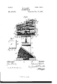
- Figure 1 is a perspective of an entire organ embodying my invention in position for use.
- Fig. 2 is a perspective of the same, showing the upper half turned back, the case and action both being divided at the plane of the reeds, which appear exposed in the lower half.
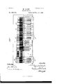
- Fig. 3 is a vertical section through the action, the case being stripped ott.
- Fig. et is a plan of the manual and valve action, part of the keys of the manual being removed to show the action underneath.
- Fig. 5 is a bottom plan of the storage-bellows, the bottom plate thereof being removed to show the mutes and their action and certain interior springs termed expressioirsprings.
- Fig. 6 is alongitudinal vertical section at the line 6 (5 on Fig. 3.
- Fig. 7 is a plan of one ot the pedals and pedalspring.
- A is the base or bottom plank constituting the lower side of the blast-bellows, of which the upper sides A A constitute the pedals in the usual position of pedals in cabinet-organs, A being the flexible back and sides of such bellows.
- the bellows are held normally with the pedals in the highest position, as shown in Fig.
- springs B 13 of any convenient form; but as illustrated and preferred they are simple torsionsprings made of heavy wire, having the end 13 secured to the base near the inner edge of thepedal and extending thence outwardly along the forward edge to the outer corner, near which it is provided with a bearing Z1, and then bent around the corner of the bellows to form a lever-arm 13 which in the normal position of the springs extends upward from the bend at a steeper inclination than the highest position of the pedal, so that some torsion is given to the spring when the lever-arm is pushed down and engaged under the stop a at the edge of the pedal, this torsion being sutficient by the upward reaction which it causes to hold the pedal normally at the highest position, and the further torsion experienced by depressing the pedal being sufficient to restore the latter promptly to its highest position, the bellows drawing in air through the inlet-valve A
- the base A is channeled on the upper side under the bellows and said channel a communicates at the ends with the lower ends respectively
- D is top of the storage-bellows or compression-chamber and the bottom of the reedchamber.
- D is the bottom of the storage or compression chamber.
- the walls of said compressionchamber comprise the rigid part D and the flexible or bellows part D the latter being joined air-tight to the bottom D and to the rigid portion D of the sides.
- E E E E E are springs which react upwardly against the bottom of the storage-bellows D, being stopped at their lower ends by ledgesc on the legs 0, and F F are springs within the storage-bellows and which may be, as illustrated,secured to the under side of the top D thereof and which, when stopped at their lower ends against the bottom of said chamber or any projection therefrom, tend by their downward reaction to resist the collapse of the storage-bellows by the rising of the bottom D thereof.
- springs F are less powerful than the springs E, the latter being strong enough to collapse the storage-bellows, notwithstanding the resistance of the springs E, which, however, are preferably strong enough so that at the limit of the upward or collapsing movement of the bellows, (bottom D,) the springs E in that movement steadily diminishing in pressure and the springs F steadily increasing in resistance, the two are properly balanced.
- the communication of the tubular posts (J with the storage-bellows is made through the end portions of the rigid part D of said bellows.
- G is a shallow chamber above the compression chamber or storage bellows, serving merely to distribute the air from the storagebellows to all the reeds, and itis partitioned, as at G, to form a separate compartment underneath each set of reeds.
- Each compartment of this chamber receives air from the storage-bellows through separate openings 9 g, the mutes H H, which muffle said openings, being connected to and operated by a separate stop for each compartment. As illustrated, such mutes are hinged to the under side of the top D of the storage-bellows and close upward.
- the top of the chamber G is formed by the reed-board J.
- the marginal walls of said chamber and the partitions which separate the several compartments of said chamber may be secured indifferently to the top or to the bottom of said chamber, and their edges are covered with feltj, so that when the reed-board J covers the reed-chamber, and especially when it is bound down thereto, as hereinafter described, air-tight junctions are made by the felt-covered edges of said walls and partitions, so that when the mutes which control the openings from storage-bellows into any compartment or chamber pertaining to a given set of reeds are opened air is thereby admitted into such compartment only, which then constitutes, practically, a continuation of the storage-bellows or compression chamber.
- This chamber G may properly be named the reed-chamber, because it is the chamber in which the reeds are exposed to the air-blast, and each compart ment, when in communication with the storage-bellows by the opening of the mutes, c011- tains air at the same tension as that in the storagebellows.
- the action thus far described is divided at a plane through the reed-chamber G from the portion of the action above that plane-to wit, the plane of the felt-covered edges of the marginal walls and partitions of the chamber G, and, as hereinafter described, the remainder of the action is secured to the cover or top of this chamber-to wit, the reed-board J.
- the portion of the case which incloses the lower part of the action up to said horizontal plane of division is secured to said lower portion, and is also divided from the upper portion of the case at the same plane, and the upper portion of the case is secured to the upper portion of the action.
- the reed-board J constitutes the base of the upper part of the action, which is mounted thereon, so as to be entirely independent of all parts of the action which are below the said horizontal plane of division, so that the two parts of the action, being separable at that plane, may be handled and manipulated with entire independence. It is not material that the separation be made as in the drawingsat the upper limit of the reed-ohamber G. It may be anywhere between the storage-bellows and the reeds.
- the most convenient mode of connectingthe two parts of the action at this division plane is by hinging them at one side, and since the portions of the case inclosing the divided portions of the action are secured to their respective portions of the action and are divided at substantially the same plane as the action, the hinging together of the action is most conveniently accomplished by hinging together the parts of the case, and this is the construction which is illustrated.
- Said levers are each apertured at the point at which they cross this fulcrum-rib, and one end of the valve-spring in the form shown in Fig. 3 is inserted loosely through said aperture m and rigidly into the rib L, and thereby causes the lever to fulcrum at the point at which said aperture m is located.
- the other end of ,the spring rests upon the uppersurface of the rear end of the lever and reacts downward thereon to seat the valves M which are secured to said levers underneath their rear ends. As illustrated, these valves are secured rigidly to the levers; but I do not limit myself to this construction.
- 0 are the reed-blocks having the vibrators or reeds O.
- I mount these on the upper side of the reed-board in the following peculiar manner:
- I form the channels J for the reed-blocks, respectively, said channels being undercut laterally, forming the lateral grooves j, which receive the edges of the blocks, the center of said channels be ing open in the vertical plane of the reeds O to allow ample room for them to vibrate.
- the reeds are designed to be arranged in double rows point to pointthat is, with the vibrating ends of corresponding reeds toward each otherand the corresponding channels J are accordingly cut back from opposite directions toward each other and stop short of meeting and merging only enough to leave standing between them at their ends enough wood to form a stop for the reed-block to permit it to be inserted just far enough to bring the reed intoproper position under the valve-opening and to form a part of a partition between the compartments which pertain to the two sets of reeds, respectively, the remainder of such partition projecting up from the top of the storage-bellows and contacting said portion of the reed-block left standing between the rows of reeds.
- This construction enables me to locate two sets of reeds, and consequently two openings, very close together and still have them lead into their respective reedchambers, so that the two valves for such corresponding valve-opcnings, being rigid on one lever and operated by one key, are neverthe less opened much more nearly equally than if the construction were not such as to permit the valve-openings to be so close together.
- the reedboard is furrowed longitudinally on opposite sides of each double row of reed-channels, as at J J the Width of such furrow being substantially the length of the reed-block, except in the case of the furrow for the last row of reeds next to either edge, where it is only necessary to cut back the reed-board to the edge to obtain the necessary opportunity to insert the reeds.
- the reed-board or board which forms the entire top of the chamber G should be integral, although I have described it without regard to its being made in separate pieces or parts; but it may be formed, as the drawings indicate, by gluing onto a thin board, whose horizontal extent is sufficient to cover the whole chamber, ribs or longitudinal blocks in which the channels J are cut, as described, the furrows J being formed by space left between and at the outer sides of such blocks; but I do not limit myself to this specific mode of constructing the reed-board of several pieces.
- the compartments for the different sets of reeds formed by a longitudinal partition only; but the chamber G may be partitioned in any direction and at any point necessary to set off a compartment for any reeds which it is desired to control by a separate stop, and the term set of reeds is here used merely with this significance-2 (A, a group ofreeds controlled by one stop.
- the stop-rods ll ll which operate the mutes II II, extend out through the front of the storage-bellows and through the front of the case to their operating-knobs, which are outside of the case, and they actuate the mutes to open them by means of the inclined portions l'l Il which engage the projections 71. h on the free edge of the mutes, respectively, as the stops are actuated longitudinally.
- the flexible wall of these bellows is made of a singlepiece (Z, of rubber cloth or suitably-flexible material impervious to air, which I fold around a l four sides of the bellows, joining the ends together at any convenient point (1 and preferably not at either corner, and to the inner side of this integral piece of cloth I secure the stiffening boards or plates (i of pasteboard or similar light and comparatively stiff material, two such pieces of stiffening material of equal width being secured at each of the four sides of the bellows, said stiffeningpieces being mitered at the corners of the bellows, so that when the bellows is fully compressed these mitered edges will still just meet or perhaps not perfectly meet.
- the hook To facilitate forcing the hook onto the stud, in view of the resistance which will be experienced in compressing the felt by such action, I provide the hook with thumb and finger flanges S S on opposite sides of its pivot.
- the partitions between said compartments may be provided with a groove g in the edge, which will extend to the end of the partition and there communicate through the unpacked joints of the case with the outer air, and if the airpressure in one compartment should be enough to force the air past the felt on one side of the groove it will lind relief as soon as it reaches the grooves and will not be forced past the felt on the other side of the groove.
- I claim 1 An organ having the action divided at a plane between the reeds and the air-chamber by which the reeds are vibrated, substantially as set forth.
- An organ having the action divided at a plane between the reeds and the air-chamber by which the reeds are vibrated, and having the case also divided and secured part to the upper and part to the lower of said divided portions of the action, whereby the case and action may be parted at such division plane to give access to the reeds, substantially as set forth.
- An organ having the action divided at a plane between the reeds and the air-chamber by which the reeds are vibrated, and having the case also divided and secured part to the upper and part to the lower of said divided portions of the action, whereby the case and action may be parted at such division plane to give access to the reeds, and having the IIO two parts of said action and case hinged together at one edge, substantially as set forth.
- An organ having the action divided at a plane between the reeds and the air-chamber by which the reeds are vibrated, and having the mutes mounted with the portion of such divided action, which comprises said air-chamber and the manual valves and levers mounted with the portion having the reeds, substantially as set forth.
- An organ having the action divided at a horizontal plane through the reed-chamber and having the contacting edges of the divided vertical walls of the air-chamber provided with yielding packing to make said junctions air-tight, substantially as set forth.
- the re'edchamber bounded above by the reed-board and below by the top of the storage-bellows or compression-chamber and provided with vertical partitions dividing said chamber into compartments corresponding to and inclosing the different sets of reeds, the top of the blast-bellows being provided with apertures leading into the said compartments, respectively, mutes mounted on the compression-chamber and controlling the apertures into the several compartments, respectively, stops which actuate said mutes, and man rial-valves mounted upon the upper side of the reed-board, substantially as set forth.
- the reed chamber bounded above by the reed-board and below by the top of the storage bellows or compression-chamber and provided with vertical partitions dividing said chamber into compartments corresponding to and inclosing the different sets of reeds, the top of the blast-bellows being provided with apertures leading into the said compartments, respectively, mutes mounted on the compression-chamber and controlling the apertures into the several compartments, respectively, stops which actuate said mutes, and the manual-valves mounted upon the upper side of the reed-board, said reedchamber being divided horizontally throughout and the divided parts being separably secured together, whereby the action may be divided between the compressionchamber and the reeds, substantially as set forth.
- a reed-board provided with vertically-open channels J, having laterallyundercut grooves j to receive the edges of the reed-blocks, and having the valve-openings through the board in a position corresponding vertically to the said channels, substantially as set forth.
- a reed-chamber comprised between the reed-board upon one side and the air-chamber, the condition of Whose air-contents produces the vibration of the reeds upon the other side
- said reed-board having the reed-valve openings and having on the side within said reed-chamber the channels J, open in said chamber toward the air-chamber and provided with thelaterally-undercut grooves to receive the edges of the reed-blocks, said chamber being partitioned vertically into compartmentsinclosing, respectively, each the reeds pertaining to one stop, substantially as set forth.
- a reed-chamber bounded at one side by the reed-board and at the other side by the apertured wall of the air-chamber, the condition of whose air contents produces vibration of the reeds, such reed-board being provided on the side within said reed-chainber with channels open toward the airchamber and arranged in double rows end to end, respectively, and provided with the laterally-undercut grooves to receive the edges of the reed-blocks, the opposite wall of said reed-chamberto wit, the apertured wall of the airchamber-having ribs which contact the line between the rows of grooves and which with the material left standing between said rows constitute vertical partitions in the reed-chamber, the apertures in said air-chamber wall being between such partitions, combined with mutes which control said aperturcs and stops which actuate the mutes pertaining to the compartments of said reedchainber, respectively, substantially as set forth.
- the rib L projecting upward from the reed-board, the valve-levers extending transversely across such rib, and the springs having one end inserted loosely through said levers and rigidly into said rib and the other ends reacting against the levers to force their valve ends down onto the reed-board to close the valve-opening, substantially as set forth.
Landscapes
- Physics & Mathematics (AREA)
- Engineering & Computer Science (AREA)
- Acoustics & Sound (AREA)
- Multimedia (AREA)
- Mattresses And Other Support Structures For Chairs And Beds (AREA)
Description
(No Model.) 6 SheetsSheet 1.
M. CLARK.
CABINET ORGAN.
No. 463,572. Patented Now 1'7, 1891.
6 Sheets Sheet 2.
(No Model.)
M. CLARK. CABINET ORGAN.
Nor 463,572.
Patented Nov. 17, 1891.
WWW
(No Model.) 6 Sheets-Sheet 3.
M. CLARK.
CABINET ORGAN.
No. 463,572. Patented Nov. 17, 1891.
A" 15 JV 1 "L, A] J (No Model.) 6 Sheets-Sheet 4.
M. CLARK.
v CABINET ORGAN. No. 463,572. Patented Nov. 17, 1891.
Ne on none 000 n n ,Ziwemfor Wlbl? N o M o a e 1 6 s n e e t s s n e e t 5. M. CLARK.
GGGGGGGGGGG N.-
' Patented Nov. 17,1891.
(NoModeL) 6 SheetsSheet '6.
M. CLARK.
I CABINET ORGAN. No. 463,572. Patented. Nov. 17,1891.
&: E1 I i I 1 J E U\ k g i F; is I Zia alto]:
1 MW mm UNITED STATES PATENT OFFICE.
MELVILLE CLARK, OF CHICAGO, ILLINOIS.
CABINET-ORGAN.
SPECIFICATION forming part of Letters Patent No. 463,572, dated November 17', 1891.
Application filed February 9, 1891. Serial No. 380,744. (No model.) 0
T0 aZZ whom, it may concern.-
Be it known that I, MELviLLE CLARK, a citizen of the United States, residing at Chicago, county of Cook, and State of Illinois, have invented certain new and useful Improvements in a Cabinet-Organ, which are fully set forth in the following specification, reference being had to the accompanying drawings, forming a part thereof.
This invention belongs to the class of organs which have blast-bellows as distinguished from exhaustbellows-that is, in which the vibration of the reeds is produced by a blast of air forced through the reed blocks by pressure as distinguished from those in which the vibration is produced by air drawn through the reed-blocks by exhaustion or partial exhaustion of air from a chamber at one side.
It consists of improvements in the bellows, by means of which a better expression is obtained from the reeds, improvements in the action by which pitmen or plungers to actuate the valves are dispensed with and the action simplified in other respects, improvements in the construction of the reed board or base upon which the reed-blocks are mounted and by means of which they are rendered more readily accessible for tuning or repairs, and correlative improvements in the action and case by means of which both are divided between the plane of the reeds and the storage-bellows, the portions of the action which are re spectively above and below the reeds being joined to the corresponding portions of the case.
Other specific details of the invention are set forth in the claims.
Figure 1 is a perspective of an entire organ embodying my invention in position for use. Fig. 2 is a perspective of the same, showing the upper half turned back, the case and action both being divided at the plane of the reeds, which appear exposed in the lower half. Fig. 3 is a vertical section through the action, the case being stripped ott. Fig. et is a plan of the manual and valve action, part of the keys of the manual being removed to show the action underneath. Fig. 5 is a bottom plan of the storage-bellows, the bottom plate thereof being removed to show the mutes and their action and certain interior springs termed expressioirsprings. Fig. 6 is alongitudinal vertical section at the line 6 (5 on Fig. 3. Fig. 7 is a plan of one ot the pedals and pedalspring.
The action of this organ is constructed so as to be supported independently of the case.
A is the base or bottom plank constituting the lower side of the blast-bellows, of which the upper sides A A constitute the pedals in the usual position of pedals in cabinet-organs, A being the flexible back and sides of such bellows. The bellows are held normally with the pedals in the highest position, as shown in Fig. 3, by means of springs B 13 of any convenient form; but as illustrated and preferred they are simple torsionsprings made of heavy wire, having the end 13 secured to the base near the inner edge of thepedal and extending thence outwardly along the forward edge to the outer corner, near which it is provided with a bearing Z1, and then bent around the corner of the bellows to form a lever-arm 13 which in the normal position of the springs extends upward from the bend at a steeper inclination than the highest position of the pedal, so that some torsion is given to the spring when the lever-arm is pushed down and engaged under the stop a at the edge of the pedal, this torsion being sutficient by the upward reaction which it causes to hold the pedal normally at the highest position, and the further torsion experienced by depressing the pedal being sufficient to restore the latter promptly to its highest position, the bellows drawing in air through the inlet-valve A The base A is channeled on the upper side under the bellows and said channel a communicates at the ends with the lower ends respectively of the tubular posts or legs 0 O, which are secured to the base and extend up past the bellows and support the upper part of the action, communicating at their upper end with the compression-chamber'or storagebellows.
D is top of the storage-bellows or compression-chamber and the bottom of the reedchamber. I
D is the bottom of the storage or compression chamber. The walls of said compressionchamber comprise the rigid part D and the flexible or bellows part D the latter being joined air-tight to the bottom D and to the rigid portion D of the sides.
E E E E are springs which react upwardly against the bottom of the storage-bellows D, being stopped at their lower ends by ledgesc on the legs 0, and F F are springs within the storage-bellows and which may be, as illustrated,secured to the under side of the top D thereof and which, when stopped at their lower ends against the bottom of said chamber or any projection therefrom, tend by their downward reaction to resist the collapse of the storage-bellows by the rising of the bottom D thereof. These springs F are less powerful than the springs E, the latter being strong enough to collapse the storage-bellows, notwithstanding the resistance of the springs E, which, however, are preferably strong enough so that at the limit of the upward or collapsing movement of the bellows, (bottom D,) the springs E in that movement steadily diminishing in pressure and the springs F steadily increasing in resistance, the two are properly balanced. The communication of the tubular posts (J with the storage-bellows is made through the end portions of the rigid part D of said bellows.
G is a shallow chamber above the compression chamber or storage bellows, serving merely to distribute the air from the storagebellows to all the reeds, and itis partitioned, as at G, to form a separate compartment underneath each set of reeds. Each compartment of this chamber receives air from the storage-bellows through separate openings 9 g, the mutes H H, which muffle said openings, being connected to and operated by a separate stop for each compartment. As illustrated, such mutes are hinged to the under side of the top D of the storage-bellows and close upward. The top of the chamber G is formed by the reed-board J. The marginal walls of said chamber and the partitions which separate the several compartments of said chamber may be secured indifferently to the top or to the bottom of said chamber, and their edges are covered with feltj, so that when the reed-board J covers the reed-chamber, and especially when it is bound down thereto, as hereinafter described, air-tight junctions are made by the felt-covered edges of said walls and partitions, so that when the mutes which control the openings from storage-bellows into any compartment or chamber pertaining to a given set of reeds are opened air is thereby admitted into such compartment only, which then constitutes, practically, a continuation of the storage-bellows or compression chamber. This chamber G may properly be named the reed-chamber, because it is the chamber in which the reeds are exposed to the air-blast, and each compart ment, when in communication with the storage-bellows by the opening of the mutes, c011- tains air at the same tension as that in the storagebellows.
It will be observed that the action thus far described is divided at a plane through the reed-chamber G from the portion of the action above that plane-to wit, the plane of the felt-covered edges of the marginal walls and partitions of the chamber G, and, as hereinafter described, the remainder of the action is secured to the cover or top of this chamber-to wit, the reed-board J. The portion of the case which incloses the lower part of the action up to said horizontal plane of division is secured to said lower portion, and is also divided from the upper portion of the case at the same plane, and the upper portion of the case is secured to the upper portion of the action. The reed-board J constitutes the base of the upper part of the action, which is mounted thereon, so as to be entirely independent of all parts of the action which are below the said horizontal plane of division, so that the two parts of the action, being separable at that plane, may be handled and manipulated with entire independence. It is not material that the separation be made as in the drawingsat the upper limit of the reed-ohamber G. It may be anywhere between the storage-bellows and the reeds. It is preferably made between the board which forms the top of the storage-bellows and which has the air-apertures controlled by the mutes H and the board in which the reeds are mounted, so as to separate the mute action from the reed-valve action, as above described. The most convenient mode of connectingthe two parts of the action at this division plane is by hinging them at one side, and since the portions of the case inclosing the divided portions of the action are secured to their respective portions of the action and are divided at substantially the same plane as the action, the hinging together of the action is most conveniently accomplished by hinging together the parts of the case, and this is the construction which is illustrated.
I will now describe the upper portion of the action. Upon the upper side of the reedboard J there is mounted the man ual-fram ea rectangular frame comprising the front bar K, rear bars K K, and end bars K bounding the intermediate rectangular aperture K. This frame is blocked up a short distance from the reed-board to allow room for the valve action under it and above the reed-board. Upon the upper side of the reed-board under the manual-frame there is secured the rib L, the upper edge of which is preferably rounded and covered with felt. This rib constitutes the fulcrum for the reed-valve levers M M M, the. Said levers are each apertured at the point at which they cross this fulcrum-rib, and one end of the valve-spring in the form shown in Fig. 3 is inserted loosely through said aperture m and rigidly into the rib L, and thereby causes the lever to fulcrum at the point at which said aperture m is located. The other end of ,the spring rests upon the uppersurface of the rear end of the lever and reacts downward thereon to seat the valves M which are secured to said levers underneath their rear ends. As illustrated, these valves are secured rigidly to the levers; but I do not limit myself to this construction. The forward ends of the levers stand underneath the keys of the manual, respectively, and said keys N N are I provided with rigid projections from their under side, which reach the levers, respectively, near their rear ends. The keys are pivoted in a customary manner upon the vertical studs 7t, secured in the rear bar II of the manual-frame and guided at their forward ends by the studs 7c in the front bar K of said frame.
0 are the reed-blocks having the vibrators or reeds O. I mount these on the upper side of the reed-board in the following peculiar manner: In said reed-board I form the channels J for the reed-blocks, respectively, said channels being undercut laterally, forming the lateral grooves j, which receive the edges of the blocks, the center of said channels be ing open in the vertical plane of the reeds O to allow ample room for them to vibrate. The reeds are designed to be arranged in double rows point to pointthat is, with the vibrating ends of corresponding reeds toward each otherand the corresponding channels J are accordingly cut back from opposite directions toward each other and stop short of meeting and merging only enough to leave standing between them at their ends enough wood to form a stop for the reed-block to permit it to be inserted just far enough to bring the reed intoproper position under the valve-opening and to form a part of a partition between the compartments which pertain to the two sets of reeds, respectively, the remainder of such partition projecting up from the top of the storage-bellows and contacting said portion of the reed-block left standing between the rows of reeds. This construction enables me to locate two sets of reeds, and consequently two openings, very close together and still have them lead into their respective reedchambers, so that the two valves for such corresponding valve-opcnings, being rigid on one lever and operated by one key, are neverthe less opened much more nearly equally than if the construction were not such as to permit the valve-openings to be so close together. In order to permit the insertion and withdrawal endwise of the reed-blocks the reedboard is furrowed longitudinally on opposite sides of each double row of reed-channels, as at J J the Width of such furrow being substantially the length of the reed-block, except in the case of the furrow for the last row of reeds next to either edge, where it is only necessary to cut back the reed-board to the edge to obtain the necessary opportunity to insert the reeds.
I have shown only two sets of reeds and corresponding mutes and stops; but any number of sets may be located in the chamber G, limited only by its horizontal extent, and the above-described mode of construction is applicable whatever the number of sets of reeds employed.
It is not essential that the reed-board or board which forms the entire top of the chamber G should be integral, although I have described it without regard to its being made in separate pieces or parts; but it may be formed, as the drawings indicate, by gluing onto a thin board, whose horizontal extent is sufficient to cover the whole chamber, ribs or longitudinal blocks in which the channels J are cut, as described, the furrows J being formed by space left between and at the outer sides of such blocks; but I do not limit myself to this specific mode of constructing the reed-board of several pieces. I have shown the compartments for the different sets of reeds formed by a longitudinal partition only; but the chamber G may be partitioned in any direction and at any point necessary to set off a compartment for any reeds which it is desired to control by a separate stop, and the term set of reeds is here used merely with this significance-2 (A, a group ofreeds controlled by one stop.
The stop-rods ll ll, which operate the mutes II II, extend out through the front of the storage-bellows and through the front of the case to their operating-knobs, which are outside of the case, and they actuate the mutes to open them by means of the inclined portions l'l Il which engage the projections 71. h on the free edge of the mutes, respectively, as the stops are actuated longitudinally.
I construct the bellowsboth the blast-bob lows under the pedals and the storage-bellowsin a novel manner as follows: I will describe the storage-bellows. The flexible wall of these bellows is made of a singlepiece (Z, of rubber cloth or suitably-flexible material impervious to air, which I fold around a l four sides of the bellows, joining the ends together at any convenient point (1 and preferably not at either corner, and to the inner side of this integral piece of cloth I secure the stiffening boards or plates (i of pasteboard or similar light and comparatively stiff material, two such pieces of stiffening material of equal width being secured at each of the four sides of the bellows, said stiffeningpieces being mitered at the corners of the bellows, so that when the bellows is fully compressed these mitered edges will still just meet or perhaps not perfectly meet. The cloth at the junction of the two stiffeningpieces on each side is thus left free to fold inwardly, and the portion d of said cloth, which is not covered by the stiffening-pieces because the ends of said stiffening-pieces are mitered, as described, is free to fold and collapse in any manner in which it may, such collapse, however, naturally occurring in the form shown in Fig. 6that is to say, along the lines d cl (1'. .lhis construction differs from the construction heretofore employed, in that it has heretofore been customary to form the collapsing portion of the bellows of stiff pieces hinged together by flexible strips glued to them at their folding-points, the corner connections between such stiffening-pieces being formed by a diamond-shaped piece of flexible character glued to the four mitered edges which meet at the corner. My construction avoids the many glue-junctions, which are liable to leak, and forms the entire collapsing sides of one piece of collapsible material, and merely determines the foldinglines for the collapse by stiffening such material except at such folding-lines. 'lhe blast-bellows, being wedge-shaped, have only two instead of four corners, and the stiffening-pieces for the triangular sides are triangular instead of quadrangular; but otherwise the construction is substantially as that described. The value of the interior springs in the storage-bellows consists in their capacity to render the collapse of the bellows more gradual than it would be under the action of the exterior springs alone. \Vhen only the springs tending to collapse the bellows are employed, the volume of tone is maintained with scarcely any change during the entire collapse, or until very nearly the end, and at the completion of the collapsing action the last remaining portion of air is expelled with a puff, and the tone ends abruptly with a sharply-diminishin g volume, producing a very unpleasant effect. hen the springs which resist the collapse are employed in addition to the springs which tend to cause the collapse of the bellows, the tension of the former increases gradually after they come into action, as the collapse of the bellows continues, and so retards the collapse and causes the tone to diminish gradually and imperceptibly, and this can be taken advantage of by the operator to get finely-shaded expression from the instrument, and for this reason I call these interior springs expression-springs. It is obviously immaterial whether these springs are located inside or outside of the bellows, except that the interior location is a convenient one for the springs which resist the collapse, and the exterior one is more convenient for the springs which cause the collapse. When the storage-bellows is fully inliated, presumably the maximum power of the organ is desired, and I prefer, therefore, to make the interior or anti-collapsing springs not quite long enough to reach the bottom of the bellows when the latter is fully expanded, so that for the first inchor thereabout of the collapsing movement of the bellows there will be no resistance to the power of the exterior springs; but as the collapse continues, as will be the case if the blast-bellows are not operated powerfully enough to maintain the tension of air in the storage -bellows, the graduated effect caused by the counter operation of the two springs will be observed. In view of the division of the organ between the plane of the reeds and the storage-bellows it is necessary that the junction at the division plane should be made air-tight when the instrument is in use, and for that reason felt edges are employed on the partitions or margins of the chamber G, as represented; but the pressure of air in the chamber will often be sufficient to lift the upper section of the action enough to allow some escape if the two parts are not securely bound together, and to prevent this I provide the hooks S S at the front of the case, by which the upper section is positively secured to the lower section, and in order to draw the two together forcibly enough to compress the felt at the junction and make the said junction thereby perfectly tight I make the hook eccentric to its pivot, so that as it is forced onto the stud S it draws the top of the organ down forcibly. To facilitate forcing the hook onto the stud, in view of the resistance which will be experienced in compressing the felt by such action, I provide the hook with thumb and finger flanges S S on opposite sides of its pivot. To prevent the escape of air from one compartment to another when the pressure in the reed-chamber is great, the partitions between said compartments may be provided with a groove g in the edge, which will extend to the end of the partition and there communicate through the unpacked joints of the case with the outer air, and if the airpressure in one compartment should be enough to force the air past the felt on one side of the groove it will lind relief as soon as it reaches the grooves and will not be forced past the felt on the other side of the groove.
I claim 1. An organ having the action divided at a plane between the reeds and the air-chamber by which the reeds are vibrated, substantially as set forth.
2. An organ having the action divided at a plane between the reeds and the air-chamber by which the reeds are vibrated, and having the case also divided and secured part to the upper and part to the lower of said divided portions of the action, whereby the case and action may be parted at such division plane to give access to the reeds, substantially as set forth.
An organ having the action divided at a plane between the reeds and the air-chamber by which the reeds are vibrated, and having the case also divided and secured part to the upper and part to the lower of said divided portions of the action, whereby the case and action may be parted at such division plane to give access to the reeds, and having the IIO two parts of said action and case hinged together at one edge, substantially as set forth.
4. An organ having the action divided at a plane between the reeds and the air-chamber by which the reeds are vibrated, and having the mutes mounted with the portion of such divided action, which comprises said air-chamber and the manual valves and levers mounted with the portion having the reeds, substantially as set forth.
5. An organ having the action divided at a horizontal plane through the reed-chamber and having the contacting edges of the divided vertical walls of the air-chamber provided with yielding packing to make said junctions air-tight, substantially as set forth.
(3. An organ having the action divided at a horizontal plane through the reed-chamber and having the contacting edges of the divided vertical walls of the air-chamber provided with yielding packing to make said junctions air-tight, said divided portions of the actions being hinged together at one edge and provided with clamping-hooks at the opposite edges, whereby the packed junctions of the divided wallsof the reed-chamber may be forced tightly together, substantially as set forth.
7. In a blast organ, the re'edchamber bounded above by the reed-board and below by the top of the storage-bellows or compression-chamber and provided with vertical partitions dividing said chamber into compartments corresponding to and inclosing the different sets of reeds, the top of the blast-bellows being provided with apertures leading into the said compartments, respectively, mutes mounted on the compression-chamber and controlling the apertures into the several compartments, respectively, stops which actuate said mutes, and man rial-valves mounted upon the upper side of the reed-board, substantially as set forth.
8. In a blastorgan, the reed chamber bounded above by the reed-board and below by the top of the storage bellows or compression-chamber and provided with vertical partitions dividing said chamber into compartments corresponding to and inclosing the different sets of reeds, the top of the blast-bellows being provided with apertures leading into the said compartments, respectively, mutes mounted on the compression-chamber and controlling the apertures into the several compartments, respectively, stops which actuate said mutes, and the manual-valves mounted upon the upper side of the reed-board, said reedchamber being divided horizontally throughout and the divided parts being separably secured together, whereby the action may be divided between the compressionchamber and the reeds, substantially as set forth.
9. In an organ, a reed-board provided with vertically-open channels J, having laterallyundercut grooves j to receive the edges of the reed-blocks, and having the valve-openings through the board in a position corresponding vertically to the said channels, substantially as set forth.
10. In an organ,a reed-chamber comprised between the reed-board upon one side and the air-chamber, the condition of Whose air-contents produces the vibration of the reeds upon the other side, said reed-board having the reed-valve openings and having on the side within said reed-chamber the channels J, open in said chamber toward the air-chamber and provided with thelaterally-undercut grooves to receive the edges of the reed-blocks, said chamber being partitioned vertically into compartmentsinclosing, respectively, each the reeds pertaining to one stop, substantially as set forth.
11. In an organ, a reed-chamber bounded at one side by the reed-board and at the other side by the apertured wall of the air-chamber, the condition of whose air contents produces vibration of the reeds, such reed-board being provided on the side within said reed-chainber with channels open toward the airchamber and arranged in double rows end to end, respectively, and provided with the laterally-undercut grooves to receive the edges of the reed-blocks, the opposite wall of said reed-chamberto wit, the apertured wall of the airchamber-having ribs which contact the line between the rows of grooves and which with the material left standing between said rows constitute vertical partitions in the reed-chamber, the apertures in said air-chamber wall being between such partitions, combined with mutes which control said aperturcs and stops which actuate the mutes pertaining to the compartments of said reedchainber, respectively, substantially as set forth.
12. In combination, substantiall3 as set forth, the reed-board and the manual-frame supported thereby, the keys pivoted to said manual-frame, and the manual-levers underncaththe keys, respectively, and fulcrumed on the rced-board, the keys having each a rigid projection extending from its under side downward to its corresponding lever.
13. In combination with the reed-board having valve-apertures leading to the reeds, respectively, the rib L, projecting upward from the reed-board, the valve-levers extending transversely across such rib, and the springs having one end inserted loosely through said levers and rigidly into said rib and the other ends reacting against the levers to force their valve ends down onto the reed-board to close the valve-opening, substantially as set forth.
it. In a blast-organ, in combination with the blast-bellows and an air-conduit from the blast-bellows into the storage-bellows, springs which resist the expansion of the storage-bellows, and springs tending to resist the collapse of said bellows, the reaction of the latter springs when the collapse of the bellows com- ITS nlenees being less than that of the former In testimony whereof I have hereunto set 10 springs,but the tension of said springs being my hand, at Cl1iongo,1lli11o1s,1n the presence approximately equal-When the bellows isfully of two witnesses, this 27th day 01": January,
collapsed, substantially as set forth. 1891.
- 5 15. In an organ, a bellows having oollnpsv e t I r ing sides, all in one piece and provided with Mum ILIE CLARK stiffening parts whose edges determine the Witnesses: lines of folding in the collapse of the bellows, CHAS. S. BURTON,
substantially as set forth. JEAN ELLIOTT.
Publications (1)
| Publication Number | Publication Date |
|---|---|
| US463572A true US463572A (en) | 1891-11-17 |
Family
ID=2532444
Family Applications (1)
| Application Number | Title | Priority Date | Filing Date |
|---|---|---|---|
| US463572D Expired - Lifetime US463572A (en) | Cabinet-organ |
Country Status (1)
| Country | Link |
|---|---|
| US (1) | US463572A (en) |
-
0
- US US463572D patent/US463572A/en not_active Expired - Lifetime
Similar Documents
| Publication | Publication Date | Title |
|---|---|---|
| US463572A (en) | Cabinet-organ | |
| US3665092A (en) | Mechanically balanced keyboard and reed chamber assembly for musical instruments | |
| US2162382A (en) | Bellows-operated reed instrument | |
| US787056A (en) | Reed-organ. | |
| US253393A (en) | kelly | |
| US2559777A (en) | Child's musical instrument | |
| US3188903A (en) | Bellows operated musical instruments | |
| US1965475A (en) | Musical instrument | |
| US1014809A (en) | Interior-player piano. | |
| US1003279A (en) | Pneumatic piano-player. | |
| US795817A (en) | Automatic piano. | |
| US523649A (en) | reynolds | |
| US402427A (en) | Combined piano and harmonium | |
| US1197302A (en) | Pneumatic calliope. | |
| US527467A (en) | Reed-organ | |
| US1059324A (en) | Pneumatic attachment for pianos. | |
| US1288465A (en) | Toy reed-organ. | |
| US323829A (en) | roosevelt | |
| US437131A (en) | Reed-organ | |
| US797389A (en) | Self-playing piano. | |
| US778545A (en) | Musical instrument. | |
| US247099A (en) | Valve-tremolo for reed-organs | |
| US1120775A (en) | Combination grand piano. | |
| US683990A (en) | Tuning instrument. | |
| US518980A (en) | Pipe-organ |