US4635592A - Valve control for an internal combustion engine - Google Patents
Valve control for an internal combustion engine Download PDFInfo
- Publication number
- US4635592A US4635592A US06/709,761 US70976185A US4635592A US 4635592 A US4635592 A US 4635592A US 70976185 A US70976185 A US 70976185A US 4635592 A US4635592 A US 4635592A
- Authority
- US
- United States
- Prior art keywords
- valve control
- valves
- cams
- control according
- valve
- Prior art date
- Legal status (The legal status is an assumption and is not a legal conclusion. Google has not performed a legal analysis and makes no representation as to the accuracy of the status listed.)
- Expired - Lifetime
Links
Images


Classifications
-
- F—MECHANICAL ENGINEERING; LIGHTING; HEATING; WEAPONS; BLASTING
- F01—MACHINES OR ENGINES IN GENERAL; ENGINE PLANTS IN GENERAL; STEAM ENGINES
- F01L—CYCLICALLY OPERATING VALVES FOR MACHINES OR ENGINES
- F01L1/00—Valve-gear or valve arrangements, e.g. lift-valve gear
- F01L1/26—Valve-gear or valve arrangements, e.g. lift-valve gear characterised by the provision of two or more valves operated simultaneously by same transmitting-gear; peculiar to machines or engines with more than two lift-valves per cylinder
- F01L1/262—Valve-gear or valve arrangements, e.g. lift-valve gear characterised by the provision of two or more valves operated simultaneously by same transmitting-gear; peculiar to machines or engines with more than two lift-valves per cylinder with valve stems disposed radially from a centre which is substantially the centre of curvature of the upper wall surface of a combustion chamber
-
- F—MECHANICAL ENGINEERING; LIGHTING; HEATING; WEAPONS; BLASTING
- F01—MACHINES OR ENGINES IN GENERAL; ENGINE PLANTS IN GENERAL; STEAM ENGINES
- F01L—CYCLICALLY OPERATING VALVES FOR MACHINES OR ENGINES
- F01L1/00—Valve-gear or valve arrangements, e.g. lift-valve gear
- F01L1/20—Adjusting or compensating clearance
- F01L1/205—Adjusting or compensating clearance by means of shims or the like
-
- F—MECHANICAL ENGINEERING; LIGHTING; HEATING; WEAPONS; BLASTING
- F01—MACHINES OR ENGINES IN GENERAL; ENGINE PLANTS IN GENERAL; STEAM ENGINES
- F01L—CYCLICALLY OPERATING VALVES FOR MACHINES OR ENGINES
- F01L1/00—Valve-gear or valve arrangements, e.g. lift-valve gear
- F01L1/20—Adjusting or compensating clearance
- F01L1/22—Adjusting or compensating clearance automatically, e.g. mechanically
- F01L1/24—Adjusting or compensating clearance automatically, e.g. mechanically by fluid means, e.g. hydraulically
-
- F—MECHANICAL ENGINEERING; LIGHTING; HEATING; WEAPONS; BLASTING
- F01—MACHINES OR ENGINES IN GENERAL; ENGINE PLANTS IN GENERAL; STEAM ENGINES
- F01L—CYCLICALLY OPERATING VALVES FOR MACHINES OR ENGINES
- F01L13/00—Modifications of valve-gear to facilitate reversing, braking, starting, changing compression ratio, or other specific operations
- F01L13/0015—Modifications of valve-gear to facilitate reversing, braking, starting, changing compression ratio, or other specific operations for optimising engine performances by modifying valve lift according to various working parameters, e.g. rotational speed, load, torque
- F01L13/0036—Modifications of valve-gear to facilitate reversing, braking, starting, changing compression ratio, or other specific operations for optimising engine performances by modifying valve lift according to various working parameters, e.g. rotational speed, load, torque the valves being driven by two or more cams with different shape, size or timing or a single cam profiled in axial and radial direction
- F01L13/0042—Modifications of valve-gear to facilitate reversing, braking, starting, changing compression ratio, or other specific operations for optimising engine performances by modifying valve lift according to various working parameters, e.g. rotational speed, load, torque the valves being driven by two or more cams with different shape, size or timing or a single cam profiled in axial and radial direction with cams being profiled in axial and radial direction
-
- F—MECHANICAL ENGINEERING; LIGHTING; HEATING; WEAPONS; BLASTING
- F01—MACHINES OR ENGINES IN GENERAL; ENGINE PLANTS IN GENERAL; STEAM ENGINES
- F01L—CYCLICALLY OPERATING VALVES FOR MACHINES OR ENGINES
- F01L1/00—Valve-gear or valve arrangements, e.g. lift-valve gear
- F01L1/02—Valve drive
- F01L1/04—Valve drive by means of cams, camshafts, cam discs, eccentrics or the like
- F01L1/047—Camshafts
- F01L1/053—Camshafts overhead type
- F01L1/0532—Camshafts overhead type the cams being directly in contact with the driven valve
-
- F—MECHANICAL ENGINEERING; LIGHTING; HEATING; WEAPONS; BLASTING
- F01—MACHINES OR ENGINES IN GENERAL; ENGINE PLANTS IN GENERAL; STEAM ENGINES
- F01L—CYCLICALLY OPERATING VALVES FOR MACHINES OR ENGINES
- F01L1/00—Valve-gear or valve arrangements, e.g. lift-valve gear
- F01L1/02—Valve drive
- F01L1/04—Valve drive by means of cams, camshafts, cam discs, eccentrics or the like
- F01L1/08—Shape of cams
-
- F—MECHANICAL ENGINEERING; LIGHTING; HEATING; WEAPONS; BLASTING
- F01—MACHINES OR ENGINES IN GENERAL; ENGINE PLANTS IN GENERAL; STEAM ENGINES
- F01L—CYCLICALLY OPERATING VALVES FOR MACHINES OR ENGINES
- F01L3/00—Lift-valve, i.e. cut-off apparatus with closure members having at least a component of their opening and closing motion perpendicular to the closing faces; Parts or accessories thereof
- F01L2003/25—Valve configurations in relation to engine
- F01L2003/256—Valve configurations in relation to engine configured other than perpendicular to camshaft axis
-
- F—MECHANICAL ENGINEERING; LIGHTING; HEATING; WEAPONS; BLASTING
- F02—COMBUSTION ENGINES; HOT-GAS OR COMBUSTION-PRODUCT ENGINE PLANTS
- F02B—INTERNAL-COMBUSTION PISTON ENGINES; COMBUSTION ENGINES IN GENERAL
- F02B1/00—Engines characterised by fuel-air mixture compression
- F02B1/02—Engines characterised by fuel-air mixture compression with positive ignition
- F02B1/04—Engines characterised by fuel-air mixture compression with positive ignition with fuel-air mixture admission into cylinder
-
- F—MECHANICAL ENGINEERING; LIGHTING; HEATING; WEAPONS; BLASTING
- F02—COMBUSTION ENGINES; HOT-GAS OR COMBUSTION-PRODUCT ENGINE PLANTS
- F02B—INTERNAL-COMBUSTION PISTON ENGINES; COMBUSTION ENGINES IN GENERAL
- F02B2275/00—Other engines, components or details, not provided for in other groups of this subclass
- F02B2275/18—DOHC [Double overhead camshaft]
-
- F—MECHANICAL ENGINEERING; LIGHTING; HEATING; WEAPONS; BLASTING
- F02—COMBUSTION ENGINES; HOT-GAS OR COMBUSTION-PRODUCT ENGINE PLANTS
- F02F—CYLINDERS, PISTONS OR CASINGS, FOR COMBUSTION ENGINES; ARRANGEMENTS OF SEALINGS IN COMBUSTION ENGINES
- F02F1/00—Cylinders; Cylinder heads
- F02F1/24—Cylinder heads
- F02F1/42—Shape or arrangement of intake or exhaust channels in cylinder heads
- F02F1/4214—Shape or arrangement of intake or exhaust channels in cylinder heads specially adapted for four or more valves per cylinder
-
- F—MECHANICAL ENGINEERING; LIGHTING; HEATING; WEAPONS; BLASTING
- F02—COMBUSTION ENGINES; HOT-GAS OR COMBUSTION-PRODUCT ENGINE PLANTS
- F02F—CYLINDERS, PISTONS OR CASINGS, FOR COMBUSTION ENGINES; ARRANGEMENTS OF SEALINGS IN COMBUSTION ENGINES
- F02F1/00—Cylinders; Cylinder heads
- F02F1/24—Cylinder heads
- F02F2001/244—Arrangement of valve stems in cylinder heads
- F02F2001/245—Arrangement of valve stems in cylinder heads the valve stems being orientated at an angle with the cylinder axis
- F02F2001/246—Arrangement of valve stems in cylinder heads the valve stems being orientated at an angle with the cylinder axis and orientated radially from the combustion chamber surface
Definitions
- the invention relates to a valve control for an internal combustion engine with at least one cylinder whose cylinder head has at least one pair of valves inclined towards each other and arranged to be radially aligned with respect to the combustion chamber, the valves being operable by a common camshaft by means of conical cams.
- hemispherical combustion chambers are desirable in internal combustion engines, which require valve arrangements radially aligned with respect to the combustion chamber.
- a particularly advantageous gas exchange is obtained with a favorable utilization of the combustion chamber by providing two inlet and two outlet valves per cylinder, the valves having the same function being disposed diametrically opposed to each other with repect to the axis of the cylinder.
- subtending camshafts are used primarily for operating the valves to actuate the lifting of the valves by push-rods and rocker arms since the transmission of the lifting stroke from conventional cams of superposed camshafts to the valves of such a valve arrangement is possible only by complicated drag and toggle levers.
- subtending camshafts a suitable valve control cannot be assured for fast-running internal combustion engines because the masses to be moved do not enable accurate valve control times to be maintained. Because the valves have a relatively low flutter limit, it is not possible to attain a high rotational speed of the engine.
- the invention accomplishes this object with bucket type tappets displaceably mounted in the cylinder head between the radially aligned valves and the conically shaped cams.
- bucket type tappets between the conically shaped cams and the valves first of all enables the additional mass moved by the cam drive to be relatively small so that the attainable motor speed will not be reduced in this respect.
- the bucket type tappet which is arranged coaxially with the valve stem, may be guided in a bore of the cylinder head which accommodates the valve spring so that the transverse forces transmitted from the conical cams to the bucket type tappet may be absorbed simply by the cylinder head without subjecting the valves to any load.
- the possible length of the guide for bucket type tappets assures the absorption of the torque generated by the lifting of the cam by the bucket type tappet.
- these torque forces may be eliminated entirely if the conical cams, in the rotational position for the maximal lifting stroke, are bent in the lifting stroke range from a plane perpendicular to the axis towards the associated bucket type tappet so that the bucket type tappet is not eccentrically overrun even during the complete cam lifting stroke.
- the curvature of the cams assures in a simple manner that the bucket type tappet will always be centrally loaded, which permits a torque-free mounting of the bucket type tappets even if the angle of inclination of the individual valves is relatively large.
- any desired valve clearance may be adjusted in a simple manner because the distance of the control faces of the cams from the bucket type tappet is changed by an axial displacement of the conical cams. This removes the necessity to adjust the valve clearance by washer discs between the bucket type tappet and the valve shaft, for example.
- a possible embodiment of axially displaceably arranging the cams consists of mounting the cams on the camshaft axially displaceably, the respective axial positions of the cams being defined, for example, by nuts of the shaft.
- Another possible embodiment for adjusting the valve clearance may be obtained by dividing the camshaft and that each shaft section carrying a single cam is individually axially displaceable. In this case, the sections of the camshaft are axially held in position to fix the adjusted valve clearance, which may be effected in various manners.
- the arrangement of individually adjustable camshaft sections furthermore permits an independent adjustment of the valve clearance if the camshaft sections are hydraulically adjustable.
- each camshaft section is hydraulically actuated by a respective check valve to reduce the valve clearance because the axial position of each camshaft section is maintained with the closing of the check valve following an adjustment.
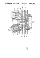
- FIG. 1 shows a valve control for an internal combustion engine according to the invention in a schematic top view on a cylinder head
- FIG. 2 is a section along line II--II of FIG. 1,
- FIG. 3 is a partial section along line III--III of FIG. 2 and
- FIG. 4 shows a modified construction in a section corresponding to that of FIG. 3.
- the illustrated internal combustion engine comprises essentially a cylinder 1 whose cylinder head 2 has two inlet valves 3 and two outlet valves 4, the arrangement being such that the valves having the same function are positioned diametrically opposite each other with respect to the cylinder axis.
- valves 3, 4 are radially aligned with respect of the combustion chamber which is closed by a spherical segment so that the axes of valve stems 5 intersect in the center of the sphere defining the spherical segment.
- a respective camshaft 6, which carries conical cams 7, is associated with each pair of valves 3, 4.
- valve stems 5 The transmission of the cam lifting stroke to valve stems 5 is effected by a respective bucket type tappet 8 which is pot-shaped and coaxially surrounds valve springs 9 and valve disc 10.
- This bucket type tappet is displaceably guided in a bore 11 of cylinder head 2 coaxial with valve stems 5 so that the transverse forces transmitted from conical cams 7 to bucket type tappets 8 may be absorbed by the cylinder head through the wall of bore 11. Since bucket type tappet 8 loosely engages valve stem 5, a force transmission is possible only in the direction of the axis of valve stem 5 and not transversely thereto.
- conical cams 7 are bent in the rotational position for the maximal lifting stroke in the range of the lifting from a plane extending perpendicularly to the axis towards the associated bucket type tappet 8 so that cup-shaped tappet 8 cannot be overrun eccentrically by the cam during the lifting stroke. Therefore, the bucket type tappet remains centrally loaded in each lifting stroke position.
- camshaft 6 is divided into two shaft sections 6a and 6b according to FIG. 3, each section being individually mounted for axial displacement in the cylinder head.
- the two shaft sections 6a and 6b are connected for common rotation but axially displaceable by an axially fixed coupling piece 12, and a multi-groove connection is provided between shaft sections 6a, 6b and coupling piece 12.
- the desired valve clearance is adjusted by an axial displacement of shaft sections 6a, 6b, their position being fixed by shims 13 in the form of half-rings of a predetermined thickness inserted between coupling piece 12 and shaft collars 14 before the shaft sections are clamped together axially with coupling piece 12 with tension bolt 15.
- shaft sections 6a, 6b are connected to pressure cylinders 16 to which pressure oil taken from the lubricating system of the motor may be fed through channels 17 in coupling piece 12 and check valves 19 mounted in axial bores 18 of the shaft sections.
- any clearance between the cam and the bucket type tappet is compensated because the pressure oil can flow through check valve 19 to pressure cylinder 16 and displaces the shaft section axially in the direction of a clearance reduction until the check valve is closed again by the pressure building up in pressure cylinder 16 so that the shaft section is held fixed in its axial position.
- Leakage losses which occur because of a pressure reduction in pressure cylinder 16 when the cam moves over the bucket type tappet in the range of its base circle, are compensated immediately because, in this case, check valve 19 is opened again.
- a flow channel 20 for a cooling medium may be accommodated between the two camshafts 6 and valves 3 and 4 associated with these camshafts, which provides favorable cooling conditions in the range of central spark plug 21, too, particularly in air-cooled motors.
Landscapes
- Engineering & Computer Science (AREA)
- Mechanical Engineering (AREA)
- General Engineering & Computer Science (AREA)
- Chemical & Material Sciences (AREA)
- Combustion & Propulsion (AREA)
- Valve-Gear Or Valve Arrangements (AREA)
- Valve Device For Special Equipments (AREA)
- Lubrication Of Internal Combustion Engines (AREA)
Applications Claiming Priority (2)
| Application Number | Priority Date | Filing Date | Title |
|---|---|---|---|
| AT0084384A AT382933B (de) | 1984-03-14 | 1984-03-14 | Ventilbetaetigung fuer hubkolben - brennkraftmaschinen |
| AT843/84 | 1984-03-14 |
Publications (1)
| Publication Number | Publication Date |
|---|---|
| US4635592A true US4635592A (en) | 1987-01-13 |
Family
ID=3501045
Family Applications (1)
| Application Number | Title | Priority Date | Filing Date |
|---|---|---|---|
| US06/709,761 Expired - Lifetime US4635592A (en) | 1984-03-14 | 1985-03-07 | Valve control for an internal combustion engine |
Country Status (4)
| Country | Link |
|---|---|
| US (1) | US4635592A (de) |
| EP (1) | EP0155261B2 (de) |
| AT (2) | AT382933B (de) |
| DE (1) | DE3571061D1 (de) |
Cited By (10)
| Publication number | Priority date | Publication date | Assignee | Title |
|---|---|---|---|---|
| US4982705A (en) * | 1990-02-21 | 1991-01-08 | Tecumseh Products Company | Cam pulley and cylinder head arrangement for an overhead cam engine |
| US5111791A (en) * | 1989-02-14 | 1992-05-12 | Yamaha Hatsudoki Kabushiki Kaisha | Cylinder head and valve train arrangement for multiple valve engine |
| EP0867601A1 (de) * | 1997-03-27 | 1998-09-30 | Toyota Jidosha Kabushiki Kaisha | Ventilsteuerung für eine Brennkraftmaschine |
| US6112717A (en) * | 1997-11-25 | 2000-09-05 | Nagano; Shigeru | Engine cylinder system |
| US6125806A (en) * | 1998-06-24 | 2000-10-03 | Yamaha Hatsudoki Kabushiki Kaisha | Valve drive system for engines |
| US6170449B1 (en) * | 1998-09-30 | 2001-01-09 | Yamaha Hatsudoki Kabushiki Kaisha | Valve operating system for engine |
| US20020187734A1 (en) * | 2001-06-12 | 2002-12-12 | Yuji Saiki | Three dimensional cam, grinding method and grinding apparatus |
| US20040182362A1 (en) * | 2003-02-24 | 2004-09-23 | Takaaki Tsukui | Internal combustion engine |
| WO2009006973A1 (de) * | 2007-07-11 | 2009-01-15 | Bayerische Motoren Werke Aktiengesellschaft | Brennkraftmaschine mit einer kurbelwelle und wenigstens einem zylinderkopf sowie kraftfahrzeug mit einer derartigen brennkraftmaschine |
| CN103277209A (zh) * | 2013-06-08 | 2013-09-04 | 清华大学 | 单缸机交叉气道缸盖总成结构 |
Families Citing this family (8)
| Publication number | Priority date | Publication date | Assignee | Title |
|---|---|---|---|---|
| AT399021B (de) * | 1985-03-18 | 1995-03-27 | Weichsler Hermann | Ventilsteuerung für brennkraftmaschinen |
| AT400971B (de) * | 1985-10-17 | 1996-05-28 | Bombardier Rotax Gmbh | Ventilsteuerung für einen zylinder einer brennkraftmaschine |
| AT404388B (de) * | 1986-02-20 | 1998-11-25 | Weichsler Hermann | Brennkraftmaschine |
| DE3818636A1 (de) * | 1988-06-01 | 1989-12-07 | Bayerische Motoren Werke Ag | Hubkolben-brennkraftmaschine mit einem zwei obenliegende steuerwellen umfassenden zylinderkopf |
| DE3838305A1 (de) * | 1988-11-11 | 1990-05-17 | Audi Ag | Zylinderkopf einer brennkraftmaschine |
| FR2668797A1 (fr) * | 1990-11-05 | 1992-05-07 | Silvetti Gabriel | Culasse pour moteurs thermiques avec soupapes a levee variable. |
| DE19731974B4 (de) | 1997-07-24 | 2006-09-07 | Peter Pelz | Hubkolbenbrennkraftmaschine |
| DE102007052251A1 (de) * | 2007-11-02 | 2009-05-07 | Daimler Ag | Ventiltriebvorrichtung |
Citations (10)
| Publication number | Priority date | Publication date | Assignee | Title |
|---|---|---|---|---|
| GB226442A (en) * | 1924-06-12 | 1924-12-24 | Montague Stanley Napier | Improvements in or relating to internal combustion engines |
| DE953672C (de) * | 1952-05-07 | 1956-12-06 | Daimler Benz Ag | Ventilsteuerung fuer Brennkraftmaschinen |
| US3481314A (en) * | 1967-08-29 | 1969-12-02 | Georges G Lecrenn | Means for optimizing the performance of internal combustion engines |
| US3638624A (en) * | 1970-04-13 | 1972-02-01 | Donald J O Grady | Engine valve control means |
| US3730150A (en) * | 1971-10-20 | 1973-05-01 | S Codner | Method and apparatus for control of valve operation |
| DE2300827A1 (de) * | 1973-01-09 | 1974-07-11 | Keller Edmund | Ventilbetaetigungssystem einer hubkolbenbrennkraftmaschine |
| JPS538415A (en) * | 1976-07-13 | 1978-01-25 | Toyota Motor Corp | Hydraulic valve lifter assembly for overhead cam-type engine |
| JPS5596310A (en) * | 1979-01-12 | 1980-07-22 | Nissan Motor Co Ltd | Valve rocking device |
| US4352344A (en) * | 1979-07-03 | 1982-10-05 | Nissan Motor Co., Ltd. | Valve operating mechanism for internal combustion engines |
| JPS57210126A (en) * | 1981-06-19 | 1982-12-23 | Yamaha Motor Co Ltd | High pressure gas fuel engine |
Family Cites Families (7)
| Publication number | Priority date | Publication date | Assignee | Title |
|---|---|---|---|---|
| FR327184A (fr) * | 1902-12-09 | 1903-06-16 | Filtz Joseph | Mécanisme de commande des soupapes d'un moteur à explosion |
| GB242919A (en) * | 1925-07-10 | 1925-11-19 | Napier & Son Ltd | Improvements in or relating to valve operating mechanism for internal combustion engines |
| GB375459A (en) * | 1931-04-07 | 1932-06-30 | Frank Albert George Butters | Improvements in or relating to the valve mechanism of internal combustion engines |
| GB467320A (en) * | 1935-12-20 | 1937-06-15 | Ludwig Apfelbeck | Improvements in cylinder-heads for internal combustion engines |
| GB558779A (en) * | 1943-05-19 | 1944-01-20 | Harold Raymond Morgan | Improvements in combustion chambers and overhead valve gear in internal combustion engines |
| GB1505643A (en) * | 1975-05-20 | 1978-03-30 | British Leyland Uk Ltd | Internal combustion engine |
| JPS5261618A (en) * | 1975-11-17 | 1977-05-21 | Nissan Motor Co Ltd | Open and close time control mechanism for inlet or exhaust valve of in ternal combustion engine |
-
1984
- 1984-03-14 AT AT0084384A patent/AT382933B/de not_active IP Right Cessation
-
1985
- 1985-03-07 US US06/709,761 patent/US4635592A/en not_active Expired - Lifetime
- 1985-03-12 DE DE8585890059T patent/DE3571061D1/de not_active Expired
- 1985-03-12 AT AT85890059T patent/ATE44074T1/de active
- 1985-03-12 EP EP85890059A patent/EP0155261B2/de not_active Expired - Lifetime
Patent Citations (10)
| Publication number | Priority date | Publication date | Assignee | Title |
|---|---|---|---|---|
| GB226442A (en) * | 1924-06-12 | 1924-12-24 | Montague Stanley Napier | Improvements in or relating to internal combustion engines |
| DE953672C (de) * | 1952-05-07 | 1956-12-06 | Daimler Benz Ag | Ventilsteuerung fuer Brennkraftmaschinen |
| US3481314A (en) * | 1967-08-29 | 1969-12-02 | Georges G Lecrenn | Means for optimizing the performance of internal combustion engines |
| US3638624A (en) * | 1970-04-13 | 1972-02-01 | Donald J O Grady | Engine valve control means |
| US3730150A (en) * | 1971-10-20 | 1973-05-01 | S Codner | Method and apparatus for control of valve operation |
| DE2300827A1 (de) * | 1973-01-09 | 1974-07-11 | Keller Edmund | Ventilbetaetigungssystem einer hubkolbenbrennkraftmaschine |
| JPS538415A (en) * | 1976-07-13 | 1978-01-25 | Toyota Motor Corp | Hydraulic valve lifter assembly for overhead cam-type engine |
| JPS5596310A (en) * | 1979-01-12 | 1980-07-22 | Nissan Motor Co Ltd | Valve rocking device |
| US4352344A (en) * | 1979-07-03 | 1982-10-05 | Nissan Motor Co., Ltd. | Valve operating mechanism for internal combustion engines |
| JPS57210126A (en) * | 1981-06-19 | 1982-12-23 | Yamaha Motor Co Ltd | High pressure gas fuel engine |
Cited By (18)
| Publication number | Priority date | Publication date | Assignee | Title |
|---|---|---|---|---|
| US5111791A (en) * | 1989-02-14 | 1992-05-12 | Yamaha Hatsudoki Kabushiki Kaisha | Cylinder head and valve train arrangement for multiple valve engine |
| US4982705A (en) * | 1990-02-21 | 1991-01-08 | Tecumseh Products Company | Cam pulley and cylinder head arrangement for an overhead cam engine |
| EP0867601A1 (de) * | 1997-03-27 | 1998-09-30 | Toyota Jidosha Kabushiki Kaisha | Ventilsteuerung für eine Brennkraftmaschine |
| US5988128A (en) * | 1997-03-27 | 1999-11-23 | Toyota Jidosha Kabushiki Kaisha | Valve driving apparatus for engine |
| US6067947A (en) * | 1997-03-27 | 2000-05-30 | Toyota Jidosha Kabushiki Kaisha | Valve driving apparatus for engine |
| US6112717A (en) * | 1997-11-25 | 2000-09-05 | Nagano; Shigeru | Engine cylinder system |
| US6125806A (en) * | 1998-06-24 | 2000-10-03 | Yamaha Hatsudoki Kabushiki Kaisha | Valve drive system for engines |
| US6170449B1 (en) * | 1998-09-30 | 2001-01-09 | Yamaha Hatsudoki Kabushiki Kaisha | Valve operating system for engine |
| US20020187734A1 (en) * | 2001-06-12 | 2002-12-12 | Yuji Saiki | Three dimensional cam, grinding method and grinding apparatus |
| US6834629B2 (en) | 2001-06-12 | 2004-12-28 | Yamaha Hatsudoki Kabushiki Kaisha | Three dimensional cam, grinding method and grinding apparatus |
| US20040182362A1 (en) * | 2003-02-24 | 2004-09-23 | Takaaki Tsukui | Internal combustion engine |
| US6892696B2 (en) * | 2003-02-24 | 2005-05-17 | Honda Motor Co., Ltd. | Internal combustion engine |
| WO2009006973A1 (de) * | 2007-07-11 | 2009-01-15 | Bayerische Motoren Werke Aktiengesellschaft | Brennkraftmaschine mit einer kurbelwelle und wenigstens einem zylinderkopf sowie kraftfahrzeug mit einer derartigen brennkraftmaschine |
| US20100050968A1 (en) * | 2007-07-11 | 2010-03-04 | Bayerische Motoren Werke Aktiengesellschaft | Internal Combustion Engine With a Crankshaft and at Least One Cylinder Head as Well as a Motor Vehicle With Such an Internal Combustion Engine |
| JP2010532839A (ja) * | 2007-07-11 | 2010-10-14 | バイエリッシェ モートーレン ウエルケ アクチエンゲゼルシャフト | クランク軸と少なくとも一つのシリンダヘッドを有する内燃機関、並びにそのような内燃機関を搭載した自動車 |
| US8307798B2 (en) | 2007-07-11 | 2012-11-13 | Bayerische Motoren Werke Aktiengesellschaft | Internal combustion engine with a crankshaft and at least one cylinder head as well as a motor vehicle with such an internal combustion engine |
| CN103277209A (zh) * | 2013-06-08 | 2013-09-04 | 清华大学 | 单缸机交叉气道缸盖总成结构 |
| CN103277209B (zh) * | 2013-06-08 | 2015-08-19 | 清华大学 | 单缸机交叉气道缸盖总成结构 |
Also Published As
| Publication number | Publication date |
|---|---|
| EP0155261A2 (de) | 1985-09-18 |
| EP0155261B1 (de) | 1989-06-14 |
| ATE44074T1 (de) | 1989-06-15 |
| EP0155261A3 (en) | 1987-01-07 |
| AT382933B (de) | 1987-04-27 |
| ATA84384A (de) | 1986-09-15 |
| EP0155261B2 (de) | 1996-03-20 |
| DE3571061D1 (en) | 1989-07-20 |
Similar Documents
| Publication | Publication Date | Title |
|---|---|---|
| US4635592A (en) | Valve control for an internal combustion engine | |
| US5345904A (en) | Valve control means | |
| US3641988A (en) | Valve-actuating mechanism for an internal combustion engine | |
| US4624222A (en) | Intake valve structure for internal combustion engine | |
| CA1074197A (en) | Valve timing mechanisms | |
| US4892067A (en) | Valve control system for engines | |
| USRE33787E (en) | Four-cycle engine | |
| US5359970A (en) | Valve drive for an internal combustion engine | |
| US5235940A (en) | Engine valve driving apparatus | |
| JPH07507119A (ja) | 駆動結合された2つの軸の間の連続的な角度調節のための装置 | |
| US5095858A (en) | Timing system, particularly for an internal combustion engine with a number of valves per cylinder | |
| US4622927A (en) | Internal combustion engine | |
| US5427064A (en) | Valve-moving apparatus for internal combustion engine | |
| US4333426A (en) | Internal combustion engine construction | |
| US4020806A (en) | Hydraulic valve lifter for internal combustion engine | |
| US5099812A (en) | Cylinder head for internal combustion engine | |
| US4502427A (en) | Rocker arm for axial engine | |
| US4610223A (en) | Cam engine | |
| US3989025A (en) | Rotary valve | |
| US6035821A (en) | Cam shaft for engine | |
| US4572117A (en) | Valve arrangement for an internal combustion engine | |
| KR100235781B1 (ko) | 밸브구동장치 | |
| US4911113A (en) | Valve actuating device for multiple valve type engine | |
| US5906186A (en) | Cylinder head for tappet arrangement for multi-valve engine | |
| US4615309A (en) | Valve actuating mechanism for internal combustion engine |
Legal Events
| Date | Code | Title | Description |
|---|---|---|---|
| AS | Assignment |
Owner name: BOMBARDIER-ROTAX GESELLSCHAFT M.B.H. A-4623 GUNSKI Free format text: ASSIGNMENT OF ASSIGNORS INTEREST.;ASSIGNOR:WEICHSLER, HERMANN;REEL/FRAME:004422/0529 Effective date: 19850227 |
|
| AS | Assignment |
Owner name: WEICHSLER, HERMANN, ROSENTALER STRASSE 218, A-9020 Free format text: ASSIGNMENT OF ASSIGNORS INTEREST.;ASSIGNOR:BOMBARDIER-ROTAX GESELLSCHAFT M.B.H. A JOINT STOCK COMPANY OF AUSTRIA;REEL/FRAME:004467/0813 Effective date: 19851017 |
|
| STCF | Information on status: patent grant |
Free format text: PATENTED CASE |
|
| CC | Certificate of correction | ||
| FPAY | Fee payment |
Year of fee payment: 4 |
|
| FPAY | Fee payment |
Year of fee payment: 8 |
|
| FPAY | Fee payment |
Year of fee payment: 12 |