US4586574A - Cutter configuration for a gage-to-shoulder transition and face pattern - Google Patents
Cutter configuration for a gage-to-shoulder transition and face pattern Download PDFInfo
- Publication number
- US4586574A US4586574A US06/496,611 US49661183A US4586574A US 4586574 A US4586574 A US 4586574A US 49661183 A US49661183 A US 49661183A US 4586574 A US4586574 A US 4586574A
- Authority
- US
- United States
- Prior art keywords
- bit
- elements
- cutting elements
- gage
- diamond
- Prior art date
- Legal status (The legal status is an assumption and is not a legal conclusion. Google has not performed a legal analysis and makes no representation as to the accuracy of the status listed.)
- Expired - Lifetime
Links
- 230000007704 transition Effects 0.000 title claims abstract description 8
- 238000005520 cutting process Methods 0.000 claims abstract description 138
- 239000010432 diamond Substances 0.000 claims description 176
- 229910003460 diamond Inorganic materials 0.000 claims description 139
- 238000005553 drilling Methods 0.000 claims description 27
- 239000011159 matrix material Substances 0.000 claims description 26
- 230000006872 improvement Effects 0.000 claims description 23
- 239000000463 material Substances 0.000 claims description 17
- 238000000034 method Methods 0.000 claims description 10
- 230000000737 periodic effect Effects 0.000 claims description 10
- 238000004519 manufacturing process Methods 0.000 claims description 6
- 230000004075 alteration Effects 0.000 claims description 5
- 230000000063 preceeding effect Effects 0.000 claims description 2
- 230000002829 reductive effect Effects 0.000 claims description 2
- 230000010076 replication Effects 0.000 claims 8
- 238000006073 displacement reaction Methods 0.000 claims 4
- 230000008595 infiltration Effects 0.000 claims 2
- 238000001764 infiltration Methods 0.000 claims 2
- 230000002028 premature Effects 0.000 abstract description 3
- 238000004904 shortening Methods 0.000 abstract 1
- 229910052751 metal Inorganic materials 0.000 description 12
- 239000002184 metal Substances 0.000 description 12
- 238000005755 formation reaction Methods 0.000 description 11
- 230000015572 biosynthetic process Effects 0.000 description 10
- 230000009471 action Effects 0.000 description 7
- 239000011435 rock Substances 0.000 description 6
- 230000008901 benefit Effects 0.000 description 5
- 239000012530 fluid Substances 0.000 description 5
- 239000007787 solid Substances 0.000 description 5
- 238000003776 cleavage reaction Methods 0.000 description 3
- 239000013078 crystal Substances 0.000 description 3
- 238000010586 diagram Methods 0.000 description 3
- 230000035515 penetration Effects 0.000 description 3
- 230000007017 scission Effects 0.000 description 3
- UONOETXJSWQNOL-UHFFFAOYSA-N tungsten carbide Chemical compound [W+]#[C-] UONOETXJSWQNOL-UHFFFAOYSA-N 0.000 description 3
- 238000005219 brazing Methods 0.000 description 2
- 230000000694 effects Effects 0.000 description 2
- 230000014759 maintenance of location Effects 0.000 description 2
- 238000005498 polishing Methods 0.000 description 2
- 238000005245 sintering Methods 0.000 description 2
- 239000004575 stone Substances 0.000 description 2
- 229920002994 synthetic fiber Polymers 0.000 description 2
- XLYOFNOQVPJJNP-UHFFFAOYSA-N water Substances O XLYOFNOQVPJJNP-UHFFFAOYSA-N 0.000 description 2
- 229910000831 Steel Inorganic materials 0.000 description 1
- 230000002411 adverse Effects 0.000 description 1
- 238000005266 casting Methods 0.000 description 1
- 239000003054 catalyst Substances 0.000 description 1
- 238000005352 clarification Methods 0.000 description 1
- 230000006835 compression Effects 0.000 description 1
- 238000007906 compression Methods 0.000 description 1
- 238000007796 conventional method Methods 0.000 description 1
- 230000007423 decrease Effects 0.000 description 1
- 238000009826 distribution Methods 0.000 description 1
- 230000003628 erosive effect Effects 0.000 description 1
- 239000010419 fine particle Substances 0.000 description 1
- 238000010438 heat treatment Methods 0.000 description 1
- 230000001771 impaired effect Effects 0.000 description 1
- 230000000670 limiting effect Effects 0.000 description 1
- 229910001092 metal group alloy Inorganic materials 0.000 description 1
- 238000005065 mining Methods 0.000 description 1
- 238000012986 modification Methods 0.000 description 1
- 230000004048 modification Effects 0.000 description 1
- 239000003129 oil well Substances 0.000 description 1
- 230000036961 partial effect Effects 0.000 description 1
- 239000003208 petroleum Substances 0.000 description 1
- 238000004663 powder metallurgy Methods 0.000 description 1
- 230000008569 process Effects 0.000 description 1
- 230000003252 repetitive effect Effects 0.000 description 1
- 230000000717 retained effect Effects 0.000 description 1
- 238000010008 shearing Methods 0.000 description 1
- 239000002904 solvent Substances 0.000 description 1
- 239000010959 steel Substances 0.000 description 1
- 230000035882 stress Effects 0.000 description 1
- 239000000758 substrate Substances 0.000 description 1
- 230000008646 thermal stress Effects 0.000 description 1
Images


Classifications
-
- E—FIXED CONSTRUCTIONS
- E21—EARTH DRILLING; MINING
- E21B—EARTH DRILLING, e.g. DEEP DRILLING; OBTAINING OIL, GAS, WATER, SOLUBLE OR MELTABLE MATERIALS OR A SLURRY OF MINERALS FROM WELLS
- E21B10/00—Drill bits
- E21B10/46—Drill bits characterised by wear resisting parts, e.g. diamond inserts
- E21B10/56—Button-type inserts
- E21B10/567—Button-type inserts with preformed cutting elements mounted on a distinct support, e.g. polycrystalline inserts
- E21B10/5673—Button-type inserts with preformed cutting elements mounted on a distinct support, e.g. polycrystalline inserts having a non planar or non circular cutting face
-
- E—FIXED CONSTRUCTIONS
- E21—EARTH DRILLING; MINING
- E21B—EARTH DRILLING, e.g. DEEP DRILLING; OBTAINING OIL, GAS, WATER, SOLUBLE OR MELTABLE MATERIALS OR A SLURRY OF MINERALS FROM WELLS
- E21B10/00—Drill bits
- E21B10/46—Drill bits characterised by wear resisting parts, e.g. diamond inserts
-
- E—FIXED CONSTRUCTIONS
- E21—EARTH DRILLING; MINING
- E21B—EARTH DRILLING, e.g. DEEP DRILLING; OBTAINING OIL, GAS, WATER, SOLUBLE OR MELTABLE MATERIALS OR A SLURRY OF MINERALS FROM WELLS
- E21B10/00—Drill bits
- E21B10/26—Drill bits with leading portion, i.e. drill bits with a pilot cutter; Drill bits for enlarging the borehole, e.g. reamers
Definitions
- the present invention relates to the field of earth boring bits and more particularly to rotary bits employing diamond cutting elements.
- the PCD products are fabricated from synthetic and/or appropriately sized natural diamond crystals under heat and pressure and in the presence of a solvent/catalyst to form the polycrystalline structure.
- the polycrystalline structures includes sintering aid material distributed essentially in the interstices where adjacent crystals have not bonded together.
- the resulting diamond sintered product is porous, porosity being achieved by dissolving out the nondiamond material or at least a portion thereof, as disclosed for example, in U.S. Pat. Nos. 3,745,623; 4,104,344 and 4,224,380.
- a porous PCD as referenced in U.S. Pat. No. 4,224,380.
- Polycrystalline diamonds have been used in drilling products either as individual compact elements or as relatively thin PCD tables supported on a cemented tungsten carbide (WC) support backings.
- the PCD compact is supported on a cylindrical slug about 13.3 mm in diameter and about 3 mm long, with a PCD table of about 0.5 to 0.6 mm in cross section on the face of the cutter.
- a stud cutter the PCD table also is supported by a cylindrical substrate of tungsten carbide of about 3 mm by 13.3 mm in diameter by 26 mm in overall length.
- These cylindrical PCD table faced cutters have been used in drilling products intended to be used in soft to medium-hard formations.
- the natural diamond could be either surface-set in a predetermined orientation, or impregnated, i.e., diamond is distributed throughout the matrix in grit or fine particle form.
- porous PCD compacts and those said to be temperature stable up to about 1200° C. are available in a variety of shapes, e.g., cylindrical and triangular.
- the triangular material typically is about 0.3 carats in weight, measures 4 mm on a side and is about 2.6 mm thick. It is suggested by the prior art that the triangular porous PCD compact be surface-set on the face with a minimal point exposure, i.e., less than 0.5 mm above the adjacent metal matrix face for rock drills.
- the difficulties with such placements are several.
- the difficulties may be understood by considering the dynamics of the drilling operation.
- a fluid such as water, air or drilling mud is pumped through the center of the tool, radially outwardly across the tool face, radially around the outer surface (gage) and then back up the bore.
- the drilling fluid clears the tool face of cuttings and to some extent cools the cutter face.
- the cuttings may not be cleared from the face, especially where the formation is soft or brittle.
- the clearance between the cutting surface-formation interface and the tool body face is relatively small and if no provision is made for chip clearance, there may be bit clearing problems.
- the weight on the drill bit normally the weight of the drill string and principally the weight of the drill collar, and the effect of the fluid which tends to lift the bit off the bottom. It has been reported, for example, that the pressure beneath a diamond bit may be as much as 1000 psi greater than the pressure above the bit, resulting in a hydraulic lift, and in some cases the hydraulic lift force exceeds 50% of the applied load while drilling.
- Run-in in synthetic PCD bits is required to break off the tip or point of the triangular cutter before efficient cutting can begin.
- the amount of tip loss is approximately equal to the total exposure of natural diamonds. Therefore, an extremely large initial exposure is required for synthetic diamonds as compared to natural diamonds. Therefore, to accommodate expected wearing during drilling, to allow for tip removal during run-in, and to provide flow clearance necessary, substantial initial clearance is needed.
- Still another advantage is the provision of a drilling tool in which thermally stable PCD elements of a defined predetermined geometry are so positioned and supported in a metal matrix as to be effectively locked into the matrix in order to provide reasonably long life of the tooling by preventing loss of PCD elements other than by normal wear.
- the improvement of the present invention includes a plurality of PCD cutting elements disposed on the apex, nose flank and shoulder of a rotating drill bit.
- the elements disposed on the apex, nose, flank and shoulder extend therefrom by a first predetermined distance.
- the rotating drill bit also includes a gage which defines the circumferential perimeter with a plurality of diamond elements disposed on the gage.
- the diamone elements disposed on the gage extend from the rotating bit by a second predetermined distance.
- the diameter of the hole bored by the rotating bit is defined by the diamond elements disposed on the gage and by the PCD elements disposed at or near a key level on the shoulder.
- the PCD cutting elements are disposed on the shoulder only up to the key level.
- the key level is defined as that level with respect to the gage of the rotating bit where the PCD element disposed at the key level defines a drilled bore substantially equal in diameter to the diameter defined by the diamond elements disposed on the gage.
- FIG. 1 is a longitudinal sectional view of a tooth improved according to the present invention.
- FIG. 2 is a plan view of the tooth shown in FIG. 1.
- FIG. 3 is a cross sectional view taken through line 3--3 of FIG. 1.
- FIG. 4 is a diagrammatic plan view of a rotating bit showing a pad layout whereon a tooth configuration improved according to the present invention is disposed.
- FIG. 5a is a diagrammatic plot detail diagram showing the placement of diamond cutting elements of the primary pads from the apex through the shoulder to the gage of the bit of FIG. 4.
- FIG. 5b is an enlarged view of a portion of the bifurcated pads of FIG. 5a shown in diagrammatic form.
- FIG. 6a is a diagrammatic profile in longitudinal cross section of the rotary bit shown in plan view in FIG. 4.
- FIG. 6b is an enlarged view of a portion of FIG. 6a included within circle 6b.
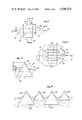
- FIG. 7 is a diagrammatic cross sectional view taken along line 7--7 of FIG. 5b showing two sizes of PCD elements adjacently disposed in a row of teeth.
- FIG. 8 is a partial diagrammatic plan view of another embodiment of the tooth plot similar to that shown in FIG. 5a wherein an alternative plot is provided on the lands.
- the present invention is an improvement in diamond tooth design and tooth configuration in a rotary bit.
- the useful life of a diamond rotating bit can be extended by using a tooth design and tooth configuration which retains the diamond cutting element on the face of the rotating cutting bit for a longer period and which maximizes the useful life of the diamond cutting element by avoiding loss and premature damage or fracture to the diamond cutting element.
- the triangular, prismatic shaped synthetic polycrystalline diamonds are exposed to the maximum extent from the bit face of the drill. However, the farther such diamonds are exposed from the bit face, the less they are embedded and secured within the bit face.
- the degree of security and retention of such a diamond cutting element can be increased by providing an integral extension of the diamond face in the form of a trailing support, the present invention has further improved the security of retention by forming a generally oval shaped collar about the base of a generally teardrop-shaped cutting tooth having a leading face formed by the diamond cutting element and about at least a portion of the trailing support forming the tail of an otherwise teardrop-shaped tooth.
- the tooth in plan view as described below takes the form and appearance of a teardrop-shaped tooth having a generally ovulate collar extending about the midsection of the tooth. This allows the diamond to be exposed to the maximum extent while providing additional integral matrix material to secure the diamond to the bit face while using a minimum of such matrix material projecting from the bit face.
- the diamond may in fact be disposed entirely above the bit face if desired.
- Tooth 10 is particularly characterised by a polycrystalline diamond cutting element 14 in combination with matrix material integrally extending from rotary bit face 12 to form a prepad 16 and trailing support 18.
- prepad 16 can be deleted without departing from the teachings of the invention.
- the nature of prepad 16 and trailing support 18 are better described in copending U.S. Pat. No. 4,491,188 assigned to the same Assignee.
- tooth 10 of FIG. 1 differs from that described in the above denoted application by reason of an integrally formed, ovulate shaped collar 20 extending from bit face 12 by a height 22.
- tooth 10 has a main body portion principally characterised by a generally triangularly prismatic shaped polycrystalline diamond element 14.
- the apical edge 24 of diamond element 14 is illustrated in solid outline while its sides 25 and base 26 are shown in dotted and solid outline in FIGS. 1-3.
- Generally oval-shaped collar 20 completely circumscribes the main body of tooth 10 and in particular, diamond element 14.
- collar 20 extends from bit face 12 by a preselected height 22 to provide additional matrix material.
- the matrix material is integrally formed with bit face 12 by conventional metallic casting and powder metallurgy techniques to more firmly embed diamond element 14 within bit face 12.
- collar 20 provides additional lateral, forward and rearward support to element 14 to secure element 14 to bit face 12.
- tooth 10 as shown in FIG. 2 forms a singular geometric shape generally described as a teardrop-shaped tooth having a generally oval-shaped collar disposed around the triangular prismatic-shaped diamond element.
- This shape is illustrative only and any tooth design could be used with equal facility in the present invention.
- FIG. 1 also shows in solid outline a second, larger similar triangular prismatic shaped diamond element 28 which has the same substantial shape as element 14 but can be included within tooth 10 as an alternative substitute cutting element of larger dimension.
- element 14 is a conventionally manufactured polycrystalline diamond stone manufactured by General Electric Company under the trademark GEOSET 2102
- larger cutting element 28 is a similarly shaped but larger polycrystalline diamond stone manufactured by General Electric Company under the trademark GEOSET 2103.
- GEOSET 2102 General Electric Company
- GEOSET 2103 the same tooth 10 may accommodate alternately either diamond cutting element while having a similar exposure profile above bit face 12.
- trailing support 18 is integrally continued through portion 30 to provide additional trailing support to the smaller diamond element 14, which portion 30 is deleted and replaced by larger diamond element 28 in the alternative embodiment when the larger diamond is used.
- Rotary bit 32 is shown illustratively as a petroleum bit divided into three symmetric sectors about center 34 of bit 32 wherein each sector is set off from the other by a main waterway 36.
- main waterways 36 are subdivided into a plurality of water courses 38 which extend from the center region of bit 32 to its periphery defined by the cylindrical sides of gage 40 of bit 32.
- a plurality of conventional collectors 42 are provided alternatively between waterways 38 in addition to symmetrically disposed junk slots 44.
- Waterways 38, collectors 42, and junk slots 44 are formed according to conventional design principles well known to the art and will not be further described here. However, it should be understood that any style rotary bit could be used in combination with the present invention without departing from the spirit and scope of the invention notwithstanding differences in the style or design of the hydraulic configuration of face of bit 32.
- Gage 40 of bit 32 is defined by a plurality of cutting elements 46 which include diamond cutting elements affixed to or disposed in gage 40.
- Such elements include synthetic diamond cutting elements as well as conventional natural diamonds set within longitudinal matrix ridges integrally formed as part of gage 40 in a conventional manner.
- FIG. 5a shows the three pads generally denoted by reference numerals 48, 50 and 52.
- the series of pads 48, 50, and 52 or truncated versions appear in sequence five times around bit 32 of FIG. 4.
- Each of the pads 48-52 are laid out flatly in FIG. 5a, although in fact the cross section of bit 32 is actually shown from the centerline 54 to the outer diameter 56 of the bore as illustrated in profile in FIG. 6a.
- Pads 48-52 thus lie on the surface of bit 32 in the cross sectional curve illustrated in FIG. 6a and in the plan view as illustrated in FIG. 4.
- FIG. 5a is a diagrammatic view of each of the pads of the repetitive sequence showing the placement of the diamond cutting elements, again diagrammatically shown and previously described in connection with the FIGS. 1-3.
- Pad 52 begins at center 34 of bit 32 and extends as a single pad from center 34 to approximately point 58 which is located at or near nose 60 of bit 32 where pad 52 broadens and divides into two separate pads generally denoted by reference characters 52a and 52b. Pads 52a and 52b are separated by a collector 42 best shown in FIG. 4. Pads 52a and 52b continue along flank 63 and shoulder 62 of bit 32 to gage 64 and thereafter continue upwardly along gage 64.
- the maximum linear velocity of bit 32 when rotated, occurs at point 66 just at the beginning of gage 64.
- Diamond cutting elements on shoulder 62 placed just below point 66 also encounter linear cutting velocities substantially near the maximum achieved by bit 32. Typically, it is the diamond cutting elements in this area that are subjected to the highest degree of wear and it is these cutting elements that usually fail first and cause bit 32 to "go out of gage".
- these cutting elements when tripping the bit in and out of the bore, it is also these cutting elements which are often subjected to the most abuse. Sometimes a bore will swell and must be reamed by these cutters. Further, in an intentional reaming operation these cutters will bear the primary brunt of the wearing action.
- the extent of projection of element 14 from bit face 12, namely distance 68, is approximately 2.6 to 2.7 millimeters when polycrystalline synthetic diamonds are used.
- the cutting elements in gage 64 are typically chosen as industrial grade natural diamonds for economic and design reasons of a size of approximately 6-8 per carat. In other embodiments new or used PCD elements, set face or side out, may be used to better advantage.
- a bit with synthetic diamond elements on the face up to the gage would always be over-gage.
- the projection of such natural diamonds is typically no more than 0.64 millimeters beyond the bit surface.
- the synthetic polycrystalline diamond cutting elements on shoulder 62 were extended to point 66 next to gage 64, such a diamond would extend approximately 2.7 millimeters from the bit face and the next adjacent diamond upwardly on gage 64, a natural diamond, would extend only 0.64 millimeters from the bit face. The result would be that the synthetic diamond would be substantially over-gage at point 66 where maximal lineal cutting velocity is incurred. Such a bit cannot be shipped to the field.
- a key level 72 is identified on shoulder 62 above which the synthetic polycrystalline diamond cutting elements are not positioned.
- pad 48b includes a polycrystalline diamond bearing tooth 96 positioned on shoulder 62 at key level 72.
- a pattern of synthetic polycrystalline diamond cutting elements are disposed below key level 72 as best seen in FIG. 5a on pads 48-52.
- shoulder 62 is provided with a patterned array of cutting elements in keyspace 90, generally denoted by reference numeral 88, each cutting element incorporating a natural diamond of a size of approximately 5 per carat.
- tooth 96 is shown at key level 72 and extends perpendicularly from the bit face of shoulder 62 by the designed amount of approximately 6.7 millimeters. 5 per carat natural diamonds 88 are then positioned in a transition region or keyspace 90 on shoulder 62 to gage point 66.
- key level 72 is chosen so that uppermost polycrystalline synthetic diamond tooth 96 extends radially from center line 54 by an amount substantially equal to the extent of gage teeth 70 from center line 54 of bit 32 as indicated by line 91 in FIG. 6b.
- tooth 96 is "in gage” and no other principal cutting tooth is positioned on the bit face of bit 32 beyond the designed gage diameter.
- Transition diamonds 88 thus provide a gage-type keyspace 90 transitioning into smaller 6 to 8 per carat gage diamonds 70 on gage 64.
- Both GEOSETS 2102 and 2103 are shown in FIG. 6b with the larger 2103 GEOSET shown in dotted outline and the smaller 2102 GEOSETS shown in solid outline.
- FIGS. 5a and 5b show the GEOSETS symbolically as open triangles and circles, with the solid circles being natural diamond.
- FIG. 6b shows the diamond cutting elements in their ideal geometric shape where round natural diamonds are depicted for the sake of clarity as spherical. Clearly, other shaped diamonds could be substituted for the rounded natural diamonds.
- Circular elements representing teeth 82 and 95 indicate a first polycrystalline synthetic diamond type, such as the triangular prismatic diamond GEOSET 2102, having equilateral triangular faces of approximately 4.0 millimeters and a thickness of 2.6 millimeters.
- Teeth 95 and 82 thus include a GEOSET 2102 diamond while teeth 83 and 96 include a similarly shaped triangular prismatic synthetic polycrystalline diamond GEOSET 2103, having an equilateral triangular face of approximately 6.0 millimeters and a thickness of 3.7 millimeters.
- Teeth 82 and 83 are in line with radially adjacent teeth 67 and 69 which include a 5 per carat natural diamond.
- the pattern of teeth 96, 83, 69, 98, 92 and 65 form a pattern which is again repeated at least partially on pads 48a and 48b.
- polycrystalline synthetic diamond bearing teeth are placed on a single row on or near the leading edge of pads 48a and 48b down to the point where each of these pads merge to form single land 48.
- Single pad 48 then continues with a double row of teeth on portion 118, one row being of polycrystalline synthetic material and the other row including 5 per carat natural diamond material.
- the very tip portion 116 is then heavily provided with scrap portions of polycrystalline synthetic material which are recycled from previosly worn bits or set with various types of natural diamonds.
- Pads 50 and 52 are provided with similar patterns.
- pads 48-52 are repeated about a bit face in a repetitious pattern with only three pads reproduced in full length as shown in FIG. 5a. Most of the pads are truncated or shortened to provide room for main waterways 36 of bit 32. Bit face designs other than that shown in FIG. 4 could have been used with the tooth placement of FIGS. 5a-b and 6a-b. For example, in other designs, pads 48-52 as shown in FIG. 5a or portions thereof may be repeated only three or four times about the bit face rather than the five times illustrated in the design of FIG. 4.
- FIGS. 5a, 5b and 6b wherein the relationship between the spacing of teeth on adjacent pads is described.
- FIG. 5b and bifurcated pads 52a, 52b of pad 52 shown in its entirety in FIG. 5a and in fragmentary view in FIG. 5b.
- tooth 73 on pad 52a and tooth 74 on pad 52b are in line with each other and can be considered as the starting point or initial reference location for all other teeth on the bit as will be described in the following.
- the distance between two adjacent teeth in the same row on the same pad is defined as a unit of spacing and is uniform throughout the tooth configuration on the bit face.
- the distance between tooth 71 and 73 is a unit space, as is the distance between tooth 75 and 76 in the second row of pad 52a.
- the distance between tooth 74 and 77 is a unit space, as is the distance between teeth 78 and 79 in the second row on pad 52b.
- the unit space is thus defined as that distance between two longitudinally adjacent teeth in a given row on a pad.
- tooth 80 on pad 50a and tooth 81 on pad 50b are in line with each other and are offset away from line 1 by two-thirds of a unit space from the corresponding azimuthal level of teeth 73 and 74 on pads 52a and 52b, respectively.
- Each of the azimuthal lines vertically drawn in FIG. 5b are one sixth of the unit space apart.
- tooth 82 on pad 48a and tooth 83 on pad 48b are in line with each other and are offset away from line 1 by one-third of a unit space from the azimuthal level of teeth 73 and 74 on pads 52a and 52b, respectively. This pattern is repeated every three pads circumferentially around the bit.
- tooth 71 on pad 52a and tooth 77 on pad 52b are in line with each other and offset from teeth 73 and 74 by one unit spacing longitudinally along the face of the bit.
- Tooth 86 on pad 50a and tooth 87 on pad 50b are similarly longitudinally offset from tooth 80 on pad 50a and tooth 81 on pad 50b respectively by a unit spacing, and are longitudinally offset from teeth 71 and 77 by two-thirds of a unit space.
- Tooth 89 on pad 48a and tooth 92 on pad 48b are also in line with each other and are longitudinally offset from teeth 82 and 83 respectively by one unit spacing, and are longitudinally offset from teeth 71 and 77 by one-third of a unit space. Again, this pattern is repeated circumferentially around the bit for each unit of longitudinal spacing on the bit face.
- a second row of teeth is provided on each bifurcated pad which second row is disposed behind and offset behind its adjacent front row of teeth just described above by one-half of a unit space.
- tooth 97 on pad 50a is set halfway between and behind teeth 80 and 86 on pad 50a.
- the teeth in the second row are set in a pattern similar to the pattern just described.
- the teeth within the second row on each of the pads are related to the second row teeth on adjacent pads by offset longitudinal spacing of multiples of one-third of the unit space in the same manner as the teeth of the first row.
- Teeth are disposed on the bit face according to the described pattern up to the region of bit shoulder 62, shown in FIG. 6b, until key point 72 is reached. However no tooth is disposed on the bit face above key level 72 or between key level 72 and gage 66 in keyspace 90.
- teeth 74 and 73 are the highest teeth on pads 52a and 52b, that is nearest gage point 66.
- Teeth 74 and 73 are one-sixth of a unit space below key level 72.
- Teeth 93 and 94 on pads 50a and 50b respectively are set one-third of a unit space below key level 72. Only teeth 95 and 96 on pads 48a and 48b respectively are set exactly at key level 72.
- teeth 95 and 96 at key level 72 occur only at the end of the cutting pattern. Therefore, beginning at key level 72, a tooth and an aligned backup tooth is presented at every one-sixth interval of a unit space from key level 72 toward center 34 of the bit.
- the tooth density is increased twofold from six per unit space for the first rows on the three bifurcated pads to twelve per unit space over the same three bifurcated pads by the addition of the offset second row of teeth on each pad.
- Each repetition of the pattern thus provides redundancy of the 12 per unit space coverage of teeth. Tooth density is thus increased greatly over the density achieved by the placement of teeth in a single row on a single pad. As a result, the cutting action is smoother, more efficient, and the life of the bit is substantially increased.
- the teeth set on pads 48-52 are further distinguished from each other by including different types of diamond material within the tooth. Therefore, there is a distribution of diamond-type material which is included and superimposed upon the geometric pattern of teeth described above.
- Tooth 73 is illustrated in FIG. 5a and 5b by a triangle to indicate that tooth 73 includes a one carat GEOSET 2103.
- Tooth 74 which is aligned behind tooth 73 and included within the first row in pad 52b includes a one-third carat GEOSET 2102.
- pads 50a and 50b include tooth 80 including a GEOSET 2102 and azimuthally aligned tooth 81, including a GEOSET 2103.
- pads 48a and 48b include tooth 82, which includes a 2102 GEOSET and tooth 83 which includes GEOSET 2103.
- tooth 84 on the first row on pad 52a the pattern is reversed.
- tooth 84 is set with a GEOSET 2103 while tooth 85 in the first row on pad 52b is set with a GEOSET 2102.
- tooth 86 includes a GEOSET 2103 and aligned tooth 87 a GEOSET 2102; and on pads 48a and 48b wherein tooth 89 includes a GEOSET 2103 and tooth 92 a GEOSET 2102.
- pads 52a and 52b include two portions 100 and 101 wherein the teeth alternately include polycrystalline diamond elements of differing sizes, namely, a GEOSET 2102 diamond alternated with a GEOSET 2103 diamond. Since in each case, regardless of diamond size, the extent of the tooth projection from the bit face is identical for each tooth in portions 100 and 101, the different sized diamond elements included within the teeth result in alternating extents of disposition within the matrix material of the bit face, namely, the larger 2103 diamond is embedded more deeply than the smaller 2102 diamond. This is shown in FIG. 7 in diagrammatic sectional view along line 7--7 in FIG. 5b of pad 48b.
- a higher density of deeply embedded, large diamond cutting elements can be achieved than would otherwise be possible.
- the larger diamonds tend to be more impact resistant and their fixation to the bit is more erosion resistant. Therefore, a mixed series of larger and smaller diamonds provides better performance than a similar series of only smaller diamonds, and is more economical to manufacture than a similar series of only larger diamonds.
- FIG. 8 a second embodiment of a tooth or diamond plot in addition to that shown in FIG. 5a is diagrammatically illustrated in symbolic plan view.
- the plot of FIG. 8 differs primarily from that of FIG. 5a in that the total number of alternating larger GEOSET 2103 diamonds and smaller GEOSET 2102 diamonds set as described above in connection with FIG. 7 has been increased and second rows 102 and 104 of such alternating diamond-bearing teeth have been disposed on each pad behind its corresponding leading rows 106 and 108, respectively, which leading rows are also shown on the pads of the plot diagram of FIG. 5a as portions 100 and 101. Rows 102 and 104 have been shown collectively in the case of pad 48 as encircled in dotted outline for the purposes of clarity of description.
- the number of larger GEOSETS 2103 in row 106 are in the embodiment of FIG. 8 reduced to three in number, whereas in the corresponding row in the embodiment of FIG. 5a, four such GEOSETS 2103 are used at the similar portion 100 of pad 52.
- the second row, row 102, corresponding to row 106 and row 104 corresponding to row 108 of diamond elements on pad 52 are positioned on the pad to lie behind and in the half spaces between the diamond elements in the preceeding row. Namely, diamond element 114 is placed behind and halfway between leading diamond elements 110 and 112. Otherwise, placement of diamonds on the pads as illustrated in the plot diagram of FIG. 8 is substantially identical to that described in connection with the embodiment of FIG. 5a.
- a plot setting as shown in FIG. 8 provides additional cutting capacity and bit life, particularly near nose 60 of the bit.
- both improved performance and bit life can be achieved without both improved performance and bit life can be achieved without substantially increasing the number of diamond elements used in the bit and thus increasing its cost.
- nose 60 may be subject to greater abuse than flank 63 because of the vertical weight of the drill string is supported in large part directly by nose 60.
- a double row of teeth including a high proportion of larger 2103 GEOSETS is provided on the shoulder up to key level 72 to accommodate the greater wear and abuse to which such peripherally located teeth are subjected.
- the remaining portions of the bit are then provided with smaller diamond elements and a lower tooth density suitable to those more lightly worn or abused portions of the bit.
Priority Applications (8)
| Application Number | Priority Date | Filing Date | Title |
|---|---|---|---|
| US06/496,611 US4586574A (en) | 1983-05-20 | 1983-05-20 | Cutter configuration for a gage-to-shoulder transition and face pattern |
| ZA843409A ZA843409B (en) | 1983-05-20 | 1984-05-07 | Cutting configuration for a gage-to-shoulder transition and face pattern |
| AU28065/84A AU2806584A (en) | 1983-05-20 | 1984-05-16 | Configuration and pattern of diamond inserts |
| EP84105607A EP0127077B1 (fr) | 1983-05-20 | 1984-05-17 | Trépan de forage rotatif |
| DE8484105607T DE3479142D1 (en) | 1983-05-20 | 1984-05-17 | A rotatable drill bit |
| BR8402398A BR8402398A (pt) | 1983-05-20 | 1984-05-18 | Broca giratoria |
| CA000454663A CA1214771A (fr) | 1983-05-20 | 1984-05-18 | Configuration d'outil de coupe au site de la transition du diametre effectif et de l'epaulement du porte-outil, et agencement des dents |
| JP59099730A JPS59217890A (ja) | 1983-05-20 | 1984-05-19 | 回転ビツトにおけるゲ−ジと肩部間のカツタ配置とビツト面パタ−ン |
Applications Claiming Priority (1)
| Application Number | Priority Date | Filing Date | Title |
|---|---|---|---|
| US06/496,611 US4586574A (en) | 1983-05-20 | 1983-05-20 | Cutter configuration for a gage-to-shoulder transition and face pattern |
Publications (1)
| Publication Number | Publication Date |
|---|---|
| US4586574A true US4586574A (en) | 1986-05-06 |
Family
ID=23973404
Family Applications (1)
| Application Number | Title | Priority Date | Filing Date |
|---|---|---|---|
| US06/496,611 Expired - Lifetime US4586574A (en) | 1983-05-20 | 1983-05-20 | Cutter configuration for a gage-to-shoulder transition and face pattern |
Country Status (8)
| Country | Link |
|---|---|
| US (1) | US4586574A (fr) |
| EP (1) | EP0127077B1 (fr) |
| JP (1) | JPS59217890A (fr) |
| AU (1) | AU2806584A (fr) |
| BR (1) | BR8402398A (fr) |
| CA (1) | CA1214771A (fr) |
| DE (1) | DE3479142D1 (fr) |
| ZA (1) | ZA843409B (fr) |
Cited By (27)
| Publication number | Priority date | Publication date | Assignee | Title |
|---|---|---|---|---|
| US4673044A (en) * | 1985-08-02 | 1987-06-16 | Eastman Christensen Co. | Earth boring bit for soft to hard formations |
| US4697653A (en) * | 1986-03-07 | 1987-10-06 | Eastman Christensen Company | Diamond setting in a cutting tooth in a drill bit with an increased effective diamond width |
| US4883136A (en) * | 1986-09-11 | 1989-11-28 | Eastman Christensen Co. | Large compact cutter rotary drill bit utilizing directed hydraulics for each cutter |
| US5025873A (en) * | 1989-09-29 | 1991-06-25 | Baker Hughes Incorporated | Self-renewing multi-element cutting structure for rotary drag bit |
| US5238075A (en) * | 1992-06-19 | 1993-08-24 | Dresser Industries, Inc. | Drill bit with improved cutter sizing pattern |
| US5282513A (en) * | 1992-02-04 | 1994-02-01 | Smith International, Inc. | Thermally stable polycrystalline diamond drill bit |
| US5467836A (en) * | 1992-01-31 | 1995-11-21 | Baker Hughes Incorporated | Fixed cutter bit with shear cutting gage |
| EP0905348A2 (fr) * | 1994-10-31 | 1999-03-31 | The Red Baron (Oil Tools Rental) Limited | Lame de coupe pour élargisseur |
| US6123160A (en) * | 1997-04-02 | 2000-09-26 | Baker Hughes Incorporated | Drill bit with gage definition region |
| US6206117B1 (en) | 1997-04-02 | 2001-03-27 | Baker Hughes Incorporated | Drilling structure with non-axial gage |
| US6290007B2 (en) * | 1997-09-08 | 2001-09-18 | Baker Hughes Incorporated | Rotary drill bits for directional drilling employing tandem gage pad arrangement with cutting elements and up-drill capability |
| US20040149493A1 (en) * | 2003-01-31 | 2004-08-05 | Smith International, Inc. | Multi-lobed cutter element for drill bit |
| US20040163851A1 (en) * | 2003-02-21 | 2004-08-26 | Smith International, Inc. | Drill bit cutter element having multiple cusps |
| US20060011388A1 (en) * | 2003-01-31 | 2006-01-19 | Mohammed Boudrare | Drill bit and cutter element having multiple extensions |
| US20060260846A1 (en) * | 2005-05-17 | 2006-11-23 | Smith International, Inc. | Drill Bit and Cutting Inserts For Hard/Abrasive Formations |
| US20060283639A1 (en) * | 2005-06-21 | 2006-12-21 | Zhou Yong | Drill bit and insert having bladed interface between substrate and coating |
| US20070084640A1 (en) * | 2005-10-18 | 2007-04-19 | Smith International, Inc. | Drill bit and cutter element having aggressive leading side |
| US20080053710A1 (en) * | 2006-09-05 | 2008-03-06 | Smith International, Inc. | Drill bit with cutter element having multifaceted, slanted top cutting surface |
| US20080156542A1 (en) * | 2007-01-03 | 2008-07-03 | Smith International, Inc. | Rock Bit and Inserts With Wear Relief Grooves |
| US20080156543A1 (en) * | 2007-01-03 | 2008-07-03 | Smith International, Inc. | Rock Bit and Inserts With a Chisel Crest Having a Broadened Region |
| US20080156544A1 (en) * | 2007-01-03 | 2008-07-03 | Smith International, Inc. | Drill bit with cutter element having crossing chisel crests |
| US7631709B2 (en) | 2007-01-03 | 2009-12-15 | Smith International, Inc. | Drill bit and cutter element having chisel crest with protruding pilot portion |
| WO2012078220A1 (fr) * | 2010-12-06 | 2012-06-14 | Varel International, Ind., L.P. | Amélioration de durée de vie d'épaulement pour un trépan p.d.c. utilisant des éléments de coupe secondaires et tertiaires |
| US8607899B2 (en) | 2011-02-18 | 2013-12-17 | National Oilwell Varco, L.P. | Rock bit and cutter teeth geometries |
| US9279290B2 (en) | 2012-12-28 | 2016-03-08 | Smith International, Inc. | Manufacture of cutting elements having lobes |
| US10702975B2 (en) | 2015-01-12 | 2020-07-07 | Longyear Tm, Inc. | Drilling tools having matrices with carbide-forming alloys, and methods of making and using same |
| US11828108B2 (en) | 2016-01-13 | 2023-11-28 | Schlumberger Technology Corporation | Angled chisel insert |
Families Citing this family (11)
| Publication number | Priority date | Publication date | Assignee | Title |
|---|---|---|---|---|
| DE3579484D1 (de) * | 1984-03-26 | 1990-10-11 | Eastman Christensen Co | Mehrkomponenten-schneidelement mit dreieckigen, viereckigen und mehreckigen polykristallinen diamantscheiben. |
| DE3570480D1 (en) * | 1984-03-26 | 1989-06-29 | Eastman Christensen Co | Multi-component cutting element using consolidated rod-like polycrystalline diamond |
| AU3946885A (en) * | 1984-03-26 | 1985-10-03 | Norton Christensen Inc. | Cutting element using polycrystalline diamond disks |
| CN86100885A (zh) * | 1985-01-25 | 1986-08-20 | 诺顿-克里斯坦森公司 | 一种改进的沟槽切削型钻头 |
| US4744427A (en) * | 1986-10-16 | 1988-05-17 | Eastman Christensen Company | Bit design for a rotating bit incorporating synthetic polycrystalline cutters |
| US4869330A (en) * | 1988-01-20 | 1989-09-26 | Eastman Christensen Company | Apparatus for establishing hydraulic flow regime in drill bits |
| GB2294069B (en) * | 1994-10-15 | 1998-10-28 | Camco Drilling Group Ltd | Improvements in or relating to rotary drills bits |
| DE69531277T2 (de) * | 1994-10-15 | 2004-05-19 | Camco Drilling Group Ltd., Stonehouse | Drehbohrmeissel |
| US6253863B1 (en) | 1999-08-05 | 2001-07-03 | Smith International, Inc. | Side cutting gage pad improving stabilization and borehole integrity |
| US6684967B2 (en) | 1999-08-05 | 2004-02-03 | Smith International, Inc. | Side cutting gage pad improving stabilization and borehole integrity |
| US6575256B1 (en) | 2000-01-11 | 2003-06-10 | Baker Hughes Incorporated | Drill bit with lateral movement mitigation and method of subterranean drilling |
Citations (1)
| Publication number | Priority date | Publication date | Assignee | Title |
|---|---|---|---|---|
| US3727704A (en) * | 1971-03-17 | 1973-04-17 | Christensen Diamond Prod Co | Diamond drill bit |
Family Cites Families (8)
| Publication number | Priority date | Publication date | Assignee | Title |
|---|---|---|---|---|
| US3135341A (en) * | 1960-10-04 | 1964-06-02 | Christensen Diamond Prod Co | Diamond drill bits |
| US3709308A (en) * | 1970-12-02 | 1973-01-09 | Christensen Diamond Prod Co | Diamond drill bits |
| GB1367520A (en) * | 1971-11-19 | 1974-09-18 | Shell Int Research | Diamond bit |
| US4073354A (en) * | 1976-11-26 | 1978-02-14 | Christensen, Inc. | Earth-boring drill bits |
| US4234048A (en) * | 1978-06-12 | 1980-11-18 | Christensen, Inc. | Drill bits embodying impregnated segments |
| US4373593A (en) * | 1979-03-16 | 1983-02-15 | Christensen, Inc. | Drill bit |
| US4529047A (en) * | 1983-02-24 | 1985-07-16 | Norton Christensen, Inc. | Cutting tooth and a rotating bit having a fully exposed polycrystalline diamond element |
| US4491188A (en) * | 1983-03-07 | 1985-01-01 | Norton Christensen, Inc. | Diamond cutting element in a rotating bit |
-
1983
- 1983-05-20 US US06/496,611 patent/US4586574A/en not_active Expired - Lifetime
-
1984
- 1984-05-07 ZA ZA843409A patent/ZA843409B/xx unknown
- 1984-05-16 AU AU28065/84A patent/AU2806584A/en not_active Abandoned
- 1984-05-17 EP EP84105607A patent/EP0127077B1/fr not_active Expired
- 1984-05-17 DE DE8484105607T patent/DE3479142D1/de not_active Expired
- 1984-05-18 BR BR8402398A patent/BR8402398A/pt unknown
- 1984-05-18 CA CA000454663A patent/CA1214771A/fr not_active Expired
- 1984-05-19 JP JP59099730A patent/JPS59217890A/ja active Pending
Patent Citations (1)
| Publication number | Priority date | Publication date | Assignee | Title |
|---|---|---|---|---|
| US3727704A (en) * | 1971-03-17 | 1973-04-17 | Christensen Diamond Prod Co | Diamond drill bit |
Non-Patent Citations (2)
| Title |
|---|
| General Electric, "Geoset Drill Diamond", SMD18-404(10M), Oct. 1982. |
| General Electric, Geoset Drill Diamond , SMD18 404(10M), Oct. 1982. * |
Cited By (42)
| Publication number | Priority date | Publication date | Assignee | Title |
|---|---|---|---|---|
| US4673044A (en) * | 1985-08-02 | 1987-06-16 | Eastman Christensen Co. | Earth boring bit for soft to hard formations |
| US4697653A (en) * | 1986-03-07 | 1987-10-06 | Eastman Christensen Company | Diamond setting in a cutting tooth in a drill bit with an increased effective diamond width |
| US4883136A (en) * | 1986-09-11 | 1989-11-28 | Eastman Christensen Co. | Large compact cutter rotary drill bit utilizing directed hydraulics for each cutter |
| US5025873A (en) * | 1989-09-29 | 1991-06-25 | Baker Hughes Incorporated | Self-renewing multi-element cutting structure for rotary drag bit |
| US5467836A (en) * | 1992-01-31 | 1995-11-21 | Baker Hughes Incorporated | Fixed cutter bit with shear cutting gage |
| US5282513A (en) * | 1992-02-04 | 1994-02-01 | Smith International, Inc. | Thermally stable polycrystalline diamond drill bit |
| US5238075A (en) * | 1992-06-19 | 1993-08-24 | Dresser Industries, Inc. | Drill bit with improved cutter sizing pattern |
| EP0905348A2 (fr) * | 1994-10-31 | 1999-03-31 | The Red Baron (Oil Tools Rental) Limited | Lame de coupe pour élargisseur |
| EP0905348A3 (fr) * | 1994-10-31 | 1999-06-30 | The Red Baron (Oil Tools Rental) Limited | Lame de coupe pour élargisseur |
| US6206117B1 (en) | 1997-04-02 | 2001-03-27 | Baker Hughes Incorporated | Drilling structure with non-axial gage |
| US6123160A (en) * | 1997-04-02 | 2000-09-26 | Baker Hughes Incorporated | Drill bit with gage definition region |
| US6290007B2 (en) * | 1997-09-08 | 2001-09-18 | Baker Hughes Incorporated | Rotary drill bits for directional drilling employing tandem gage pad arrangement with cutting elements and up-drill capability |
| US20040149493A1 (en) * | 2003-01-31 | 2004-08-05 | Smith International, Inc. | Multi-lobed cutter element for drill bit |
| US6883624B2 (en) * | 2003-01-31 | 2005-04-26 | Smith International, Inc. | Multi-lobed cutter element for drill bit |
| US20050189149A1 (en) * | 2003-01-31 | 2005-09-01 | Smith International, Inc. | Multi-lobed cutter element for drill bit |
| US20060011388A1 (en) * | 2003-01-31 | 2006-01-19 | Mohammed Boudrare | Drill bit and cutter element having multiple extensions |
| US7086489B2 (en) | 2003-01-31 | 2006-08-08 | Smith International, Inc. | Multi-lobed cutter element for drill bit |
| US20040163851A1 (en) * | 2003-02-21 | 2004-08-26 | Smith International, Inc. | Drill bit cutter element having multiple cusps |
| US6929079B2 (en) * | 2003-02-21 | 2005-08-16 | Smith International, Inc. | Drill bit cutter element having multiple cusps |
| US7690442B2 (en) | 2005-05-17 | 2010-04-06 | Smith International, Inc. | Drill bit and cutting inserts for hard/abrasive formations |
| US20060260846A1 (en) * | 2005-05-17 | 2006-11-23 | Smith International, Inc. | Drill Bit and Cutting Inserts For Hard/Abrasive Formations |
| US20060283639A1 (en) * | 2005-06-21 | 2006-12-21 | Zhou Yong | Drill bit and insert having bladed interface between substrate and coating |
| US7757789B2 (en) | 2005-06-21 | 2010-07-20 | Smith International, Inc. | Drill bit and insert having bladed interface between substrate and coating |
| US20070084640A1 (en) * | 2005-10-18 | 2007-04-19 | Smith International, Inc. | Drill bit and cutter element having aggressive leading side |
| US7624825B2 (en) | 2005-10-18 | 2009-12-01 | Smith International, Inc. | Drill bit and cutter element having aggressive leading side |
| US20080053710A1 (en) * | 2006-09-05 | 2008-03-06 | Smith International, Inc. | Drill bit with cutter element having multifaceted, slanted top cutting surface |
| US7743855B2 (en) | 2006-09-05 | 2010-06-29 | Smith International, Inc. | Drill bit with cutter element having multifaceted, slanted top cutting surface |
| US7798258B2 (en) | 2007-01-03 | 2010-09-21 | Smith International, Inc. | Drill bit with cutter element having crossing chisel crests |
| US8205692B2 (en) | 2007-01-03 | 2012-06-26 | Smith International, Inc. | Rock bit and inserts with a chisel crest having a broadened region |
| US7631709B2 (en) | 2007-01-03 | 2009-12-15 | Smith International, Inc. | Drill bit and cutter element having chisel crest with protruding pilot portion |
| US20080156544A1 (en) * | 2007-01-03 | 2008-07-03 | Smith International, Inc. | Drill bit with cutter element having crossing chisel crests |
| US20080156543A1 (en) * | 2007-01-03 | 2008-07-03 | Smith International, Inc. | Rock Bit and Inserts With a Chisel Crest Having a Broadened Region |
| US20080156542A1 (en) * | 2007-01-03 | 2008-07-03 | Smith International, Inc. | Rock Bit and Inserts With Wear Relief Grooves |
| US7950476B2 (en) | 2007-01-03 | 2011-05-31 | Smith International, Inc. | Drill bit and cutter element having chisel crest with protruding pilot portion |
| US7686106B2 (en) | 2007-01-03 | 2010-03-30 | Smith International, Inc. | Rock bit and inserts with wear relief grooves |
| WO2012078220A1 (fr) * | 2010-12-06 | 2012-06-14 | Varel International, Ind., L.P. | Amélioration de durée de vie d'épaulement pour un trépan p.d.c. utilisant des éléments de coupe secondaires et tertiaires |
| US8544568B2 (en) | 2010-12-06 | 2013-10-01 | Varel International, Inc., L.P. | Shoulder durability enhancement for a PDC drill bit using secondary and tertiary cutting elements |
| US8607899B2 (en) | 2011-02-18 | 2013-12-17 | National Oilwell Varco, L.P. | Rock bit and cutter teeth geometries |
| US9328562B2 (en) | 2011-02-18 | 2016-05-03 | National Oilwell Varco, L.P. | Rock bit and cutter teeth geometries |
| US9279290B2 (en) | 2012-12-28 | 2016-03-08 | Smith International, Inc. | Manufacture of cutting elements having lobes |
| US10702975B2 (en) | 2015-01-12 | 2020-07-07 | Longyear Tm, Inc. | Drilling tools having matrices with carbide-forming alloys, and methods of making and using same |
| US11828108B2 (en) | 2016-01-13 | 2023-11-28 | Schlumberger Technology Corporation | Angled chisel insert |
Also Published As
| Publication number | Publication date |
|---|---|
| CA1214771A (fr) | 1986-12-02 |
| EP0127077A3 (en) | 1986-02-05 |
| DE3479142D1 (en) | 1989-08-31 |
| EP0127077A2 (fr) | 1984-12-05 |
| ZA843409B (en) | 1985-07-31 |
| BR8402398A (pt) | 1985-04-02 |
| AU2806584A (en) | 1984-11-22 |
| EP0127077B1 (fr) | 1989-07-26 |
| JPS59217890A (ja) | 1984-12-08 |
Similar Documents
| Publication | Publication Date | Title |
|---|---|---|
| US4586574A (en) | Cutter configuration for a gage-to-shoulder transition and face pattern | |
| CA1206470A (fr) | Forme de dent pour outil de foration | |
| US4529047A (en) | Cutting tooth and a rotating bit having a fully exposed polycrystalline diamond element | |
| US4512426A (en) | Rotating bits including a plurality of types of preferential cutting elements | |
| US4673044A (en) | Earth boring bit for soft to hard formations | |
| US6009963A (en) | Superabrasive cutting element with enhanced stiffness, thermal conductivity and cutting efficiency | |
| US4991670A (en) | Rotary drill bit for use in drilling holes in subsurface earth formations | |
| US4550790A (en) | Diamond rotating bit | |
| US4491188A (en) | Diamond cutting element in a rotating bit | |
| US9038752B2 (en) | Rotary drag bit | |
| US9051794B2 (en) | High impact shearing element | |
| US4515226A (en) | Tooth design to avoid shearing stresses | |
| EP0186408B1 (fr) | Elément de coupe pour trépan de forage rotatif | |
| CA1248939A (fr) | Diamant polycrystallin monte en saillie dans un trepan a corps-matrice | |
| US4898252A (en) | Cutting structures for rotary drill bits | |
| CA1218355A (fr) | Dent d'outillage a element de coupe cylindrique en diamant | |
| EP0370199A1 (fr) | Tête de forage avec sable polycristallin de diamant | |
| CN114763734A (zh) | 切削元件及钻头 | |
| CA1256856A (fr) | Trepan de foration dans les gisements friables a durs | |
| JPS6332955B2 (fr) |
Legal Events
| Date | Code | Title | Description |
|---|---|---|---|
| AS | Assignment |
Owner name: CHRISTENSEN, INC., 365 BUGATTI ST., SALT LAKE CITY Free format text: ASSIGNMENT OF ASSIGNORS INTEREST.;ASSIGNOR:GRAPPENDORF, RICHARD H.;REEL/FRAME:004133/0852 Effective date: 19830509 Owner name: CHRISTENSEN, INC., A CORP. OF UTAH, UTAH Free format text: ASSIGNMENT OF ASSIGNORS INTEREST;ASSIGNOR:GRAPPENDORF, RICHARD H.;REEL/FRAME:004133/0852 Effective date: 19830509 |
|
| AS | Assignment |
Owner name: NORTON CHRISTENSEN, INC., Free format text: MERGER;ASSIGNOR:CHRISTENSEN, INC., A UTAH CORP., CHRISTENSEN DIAMOND PRODUCTS, U.S.A., A UTAH CORP., CHRISTENSEN DIAMIN TOOLS, INC., A UTAH CORP., ALL MERGING INTO CHRISTENSEN DIAMOND PRODUCTS, U.S.A.;REEL/FRAME:004282/0603 Effective date: 19831208 |
|
| FEPP | Fee payment procedure |
Free format text: PAYOR NUMBER ASSIGNED (ORIGINAL EVENT CODE: ASPN); ENTITY STATUS OF PATENT OWNER: LARGE ENTITY |
|
| STCF | Information on status: patent grant |
Free format text: PATENTED CASE |
|
| AS | Assignment |
Owner name: EASTMAN CHRISTENSEN COMPANY, A JOINT VENTURE OF DE Free format text: ASSIGNMENT OF ASSIGNORS INTEREST.;ASSIGNORS:NORTON COMPANY;NORTON CHRISTENSEN, INC.;REEL/FRAME:004771/0834 Effective date: 19861230 Owner name: EASTMAN CHRISTENSEN COMPANY Free format text: ASSIGNMENT OF ASSIGNORS INTEREST;ASSIGNORS:NORTON COMPANY;NORTON CHRISTENSEN, INC.;REEL/FRAME:004771/0834 Effective date: 19861230 |
|
| FEPP | Fee payment procedure |
Free format text: PAYER NUMBER DE-ASSIGNED (ORIGINAL EVENT CODE: RMPN); ENTITY STATUS OF PATENT OWNER: LARGE ENTITY Free format text: PAYOR NUMBER ASSIGNED (ORIGINAL EVENT CODE: ASPN); ENTITY STATUS OF PATENT OWNER: LARGE ENTITY |
|
| FPAY | Fee payment |
Year of fee payment: 4 |
|
| FEPP | Fee payment procedure |
Free format text: PAYOR NUMBER ASSIGNED (ORIGINAL EVENT CODE: ASPN); ENTITY STATUS OF PATENT OWNER: LARGE ENTITY Free format text: PAYER NUMBER DE-ASSIGNED (ORIGINAL EVENT CODE: RMPN); ENTITY STATUS OF PATENT OWNER: LARGE ENTITY |
|
| REMI | Maintenance fee reminder mailed | ||
| REMI | Maintenance fee reminder mailed | ||
| FPAY | Fee payment |
Year of fee payment: 8 |
|
| SULP | Surcharge for late payment | ||
| FP | Lapsed due to failure to pay maintenance fee |
Effective date: 19940511 |
|
| FPAY | Fee payment |
Year of fee payment: 12 |