US4584875A - Continuous measurement of yarn twist - Google Patents
Continuous measurement of yarn twist Download PDFInfo
- Publication number
- US4584875A US4584875A US06/606,774 US60677484A US4584875A US 4584875 A US4584875 A US 4584875A US 60677484 A US60677484 A US 60677484A US 4584875 A US4584875 A US 4584875A
- Authority
- US
- United States
- Prior art keywords
- yarn
- blade
- twist
- vibration
- edge
- Prior art date
- Legal status (The legal status is an assumption and is not a legal conclusion. Google has not performed a legal analysis and makes no representation as to the accuracy of the status listed.)
- Expired - Fee Related
Links
- 238000005259 measurement Methods 0.000 title abstract description 12
- 238000000034 method Methods 0.000 claims abstract description 22
- 238000003780 insertion Methods 0.000 claims abstract description 8
- 230000037431 insertion Effects 0.000 claims abstract description 8
- 238000013519 translation Methods 0.000 claims description 3
- 239000000835 fiber Substances 0.000 claims description 2
- 239000000463 material Substances 0.000 claims description 2
- 238000012360 testing method Methods 0.000 abstract description 5
- 230000015572 biosynthetic process Effects 0.000 abstract description 2
- 239000000470 constituent Substances 0.000 description 5
- 230000000694 effects Effects 0.000 description 2
- 238000012986 modification Methods 0.000 description 2
- 230000004048 modification Effects 0.000 description 2
- 238000007383 open-end spinning Methods 0.000 description 2
- 238000012546 transfer Methods 0.000 description 2
- 229910000831 Steel Inorganic materials 0.000 description 1
- 230000008878 coupling Effects 0.000 description 1
- 238000010168 coupling process Methods 0.000 description 1
- 238000005859 coupling reaction Methods 0.000 description 1
- 230000001419 dependent effect Effects 0.000 description 1
- 238000013461 design Methods 0.000 description 1
- 230000001066 destructive effect Effects 0.000 description 1
- 239000011810 insulating material Substances 0.000 description 1
- 238000004519 manufacturing process Methods 0.000 description 1
- 238000012544 monitoring process Methods 0.000 description 1
- 238000012856 packing Methods 0.000 description 1
- 238000012545 processing Methods 0.000 description 1
- 238000009987 spinning Methods 0.000 description 1
- 239000010959 steel Substances 0.000 description 1
- 238000011144 upstream manufacturing Methods 0.000 description 1
- 238000004804 winding Methods 0.000 description 1
Images


Classifications
-
- D—TEXTILES; PAPER
- D07—ROPES; CABLES OTHER THAN ELECTRIC
- D07B—ROPES OR CABLES IN GENERAL
- D07B7/00—Details of, or auxiliary devices incorporated in, rope- or cable-making machines; Auxiliary apparatus associated with such machines
- D07B7/02—Machine details; Auxiliary devices
- D07B7/022—Measuring or adjusting the lay or torque in the rope
-
- D—TEXTILES; PAPER
- D01—NATURAL OR MAN-MADE THREADS OR FIBRES; SPINNING
- D01H—SPINNING OR TWISTING
- D01H13/00—Other common constructional features, details or accessories
- D01H13/32—Counting, measuring, recording or registering devices
-
- G—PHYSICS
- G01—MEASURING; TESTING
- G01N—INVESTIGATING OR ANALYSING MATERIALS BY DETERMINING THEIR CHEMICAL OR PHYSICAL PROPERTIES
- G01N33/00—Investigating or analysing materials by specific methods not covered by groups G01N1/00 - G01N31/00
- G01N33/36—Textiles
- G01N33/365—Filiform textiles, e.g. yarns
Definitions
- the present invention relates to a method and means for measuring the amount of twist in a travelling length of yarn and in particular to a non-destructive method for carrying out twist measurement.
- the present invention proposes a method and means of measurement of twist in a rotating or non-rotating continuous travelling yarn which may be effected subsequent to the formation of the twisted yarn.
- the present invention provides a method of measuring twist in a translating yarn comprising sensing the frequency of vibration of a blade having an edge in contact with the translating yarn and calculating the twist of the yarn which is a function of the frequency of vibration of said blade.
- the present invention provides apparatus for measuring twist in a translating yarn comprising a blade adapted to have an edge in contact with a translating yarn, means for sensing the vibration imparted to said blade by the translation of said yarn across said edge, and means for measuring the frequency of said vibration.
- This invention measures the twist in a translating yarn, whether it is rotating or not, continuously and non-destructively, by sensing the frequency of vibration of a blade which is in contact with the moving specimen, and amplifying, processing and displaying or printing the time-varying signal obtained therefrom.
- the twist estimated by the new device and method is an accurate and precise measure of twist of a running yarn as will be appreciated by the facts:
- FIG. 1 is a schematic view of apparatus in accordance with a first embodiment of the present invention
- FIG. 2 is a schematic view of apparatus in accordance with a second embodiment of the present invention.
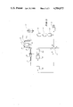
- FIG. 3 is a schematic view showing an example of how the apparatus of FIG. 1 or FIG. 2 can be used during the production of twisted yarn.
- FIG. 1 which shows a vibration sensing blade 1 with its edge 1' placed so as to remain in contact with moving yarn 2.
- Blade 1 vibrates as yarn 2 moves across edge 1'; such vibration depends upon blade design and dimensions, yarn tension, speed and surface properties but mainly the surface twist angle ⁇ .
- ⁇ the surface twist angle
- the blade 1 should have only one position at which blade vibration has its maximum amplitude giving the twist angle ⁇ . Furthermore, at constant yarn speed and tension the vibration frequency would be constant and correspond to the constant amount of twist. In the ideal case the yarn twist could be readily calculated using ⁇ and the yarn diameter according to the following:
- the procedure adopted with the apparatus of FIG. 1 is to adjust blade 1 and fix it at a specified position.
- Yarn twist is measured by sensing the frequency of the blade vibration.
- the selected blade position has its effect on the vibration amplitude.
- Vibrations imparted to blade 1 are sensed by vibration sensing elements 3 which output signals to converter 6 which transfers the vibration frequencies of blade 1 into twist values.
- Converter 6 includes appropriate electric circuits and filters providing the frequency of vibration of blade 1 as sensed by elements 3, which may be strain gauges or the like, due to the passage of yarn 2. Appropriate electric circuits and filters provide the frequency of the signal which only corresponds to yarn twist and cut-off the frequencies due to the natural frequency of the blade or due to the noise effects.
- FIG. 1 An embodiment constructed according to FIG. 1 using a steel blade 38.0 ⁇ 8.0 ⁇ 0.25 mm. employs a pair of strain gauges 3 for sensing the vibrations of the blade, one is mounted on each side of the blade 1. Strain gauges 3 are coupled to a Wheatstone bridge included in a strain gauge indicator; the output of the latter passes through a high-pass filter to cut off the frequencies due to noise and due to the electric current, and through a low-pass filter to cut-off the natural frequency of the blade. The output signal from the filters is received by a universal counter to count the corresponding frequency within a preselected time interval and it displays the average frequency. According to this embodiment the natural frequency of the blade ranges to about 800 Hz.
- the band-pass filters have to be set up such that 200 Hz ⁇ working range ⁇ 600 Hz. Therefore, this arrangement may work successfully for plied or cabled yarns running at slow speeds. For example for cabled yarn/3 singles with nominal twist of 3 turns/cm, this embodiment may be used for continuous twist measurement for speeds between 13 and 40 m/min.
- FIG. 2 shows a schematic drawing of this embodiment wherein the yarn 2 passes across the edge of the miniature blade 1, which is glued on one side of the piezo electric bimorph 3.
- the bimorph 3 is mounted cantilever fashion between the two poles 4 which are fixed in casing 5 made of insulating material.
- the bimorph 3 and the poles 4 are surrounded by rubber rings 7 as acoustic insulating packings.
- the piezo electric bimorph 3 as a generator; it transfers the mechanical vibration of the blade-end into alternating electric current at the poles 4. For every mechanical vibration of the blade 1, an electric wave of one cycle is produced at the pole 4.
- the output signal is received by the converter 6 which includes appropriate electric circuits and filters to process the signal, display and/or compute the twist values.
- the natural frequency of the blade could be higher than, say 5 kHz.
- the working range of this version may be: 200 Hz ⁇ working range ⁇ 4 kHz which can accomodate twist measurements at higher speeds as well as the twist measurements of single yarns. For example for the same cabled yarn mentioned before (3 singles with 3 turns/cm) this embodiment is capable of measuring ply twist at speeds between 15 and 270 m/min.
- h lead of a helical thread, i.e. the length of one turn of twist in cm, or
- p pitch in cm, i.e. the distance between two consecutive crests, or
- the value of (f/ ⁇ ) may be considered as the measuring index I b of the blade vibration device.
- K b is the proportionality constant
- m is not necessarily equal to N. This is because some of the yarn constituent elements exist inside the yarn body as a core and may not appear on the yarn surface. To determine m in these cases, the pattern taken by the yarn constituent elements has to be found out. Accordingly m may be calculated.
- FIG. 3 where there is shown apparatus of the type of FIG. 1 or FIG. 2 mounted as an on-line twist sensing and monitoring component of a control system in an open-end spinning process.
- the input fibre material 7, e.g. sliver, roving or tops, is fed to the twist insertion device 8, e.g., an open-end spinning rotor, and delivered as a spun yarn with constant speed by the nip rollers 9.
- the yarn 2 runs with constant speed over adjustable guide rollers 10 and 10a passing, in-between, over the twist measuring device 12, in contact with the edge of sensing blade edge 1.
- the yarn 2 passes through the nip rollers 9a to the winding head 11 such that the yarn tension remains constant.
- the electric signals coming out of the converter 13 (similar to the converter 6 in FIGS. 1 or 2), which correspond the to the values of blade vibration frequencies and consequently to the twist values, are integrated over a predetermined time period through integrator 14 and a signal corresponding to the mean value is delivered to amplifier 15.
- the output signal can be received by a pen recorder 16 giving a chart representing the continuous measurement of twist values and/or transmitted to comperator 17.
- the rate of twist insertion is measured by coupling a tachogenerator 20 to the motor 19, giving an electric signal corresponding to the actual rotational speed of the spinning rotor 8.
- the comperator 17 is fed with three signals, namely an adjusted nominal value A, a measured value B and the actual twist insertion rate value C, and it delivers the resultant value D.
- the latter signal D is transmitted to the variable speed device 18 which in turn controls the motor speed so that the yarn twist produced is adjusted to the required nominal twist value and maintained constant at this value.
Landscapes
- Engineering & Computer Science (AREA)
- Textile Engineering (AREA)
- Health & Medical Sciences (AREA)
- Life Sciences & Earth Sciences (AREA)
- Chemical & Material Sciences (AREA)
- Food Science & Technology (AREA)
- Medicinal Chemistry (AREA)
- Physics & Mathematics (AREA)
- Analytical Chemistry (AREA)
- Biochemistry (AREA)
- General Health & Medical Sciences (AREA)
- General Physics & Mathematics (AREA)
- Immunology (AREA)
- Pathology (AREA)
- Mechanical Engineering (AREA)
- Spinning Or Twisting Of Yarns (AREA)
Applications Claiming Priority (2)
| Application Number | Priority Date | Filing Date | Title |
|---|---|---|---|
| AUPF535982 | 1982-08-12 | ||
| AUPF5359 | 1982-08-12 |
Publications (1)
| Publication Number | Publication Date |
|---|---|
| US4584875A true US4584875A (en) | 1986-04-29 |
Family
ID=3769691
Family Applications (1)
| Application Number | Title | Priority Date | Filing Date |
|---|---|---|---|
| US06/606,774 Expired - Fee Related US4584875A (en) | 1982-08-12 | 1983-08-12 | Continuous measurement of yarn twist |
Country Status (6)
| Country | Link |
|---|---|
| US (1) | US4584875A (de) |
| EP (1) | EP0118466B1 (de) |
| JP (1) | JPS59501421A (de) |
| DE (1) | DE3366095D1 (de) |
| IT (1) | IT1169761B (de) |
| WO (1) | WO1984000781A1 (de) |
Cited By (9)
| Publication number | Priority date | Publication date | Assignee | Title |
|---|---|---|---|---|
| US4719576A (en) * | 1986-07-01 | 1988-01-12 | Toray Industries, Inc. | Apparatus for measuring the degree of entanglement in a yarn |
| US4758968A (en) * | 1985-05-16 | 1988-07-19 | North Carolina State University | Method and apparatus for continuously measuring the variability of textile strands |
| US4785618A (en) * | 1986-01-18 | 1988-11-22 | Hans Stahlecker | Method for operating an open-end friction spinning machine |
| US4843879A (en) * | 1983-06-21 | 1989-07-04 | Superba S. A. | Apparatus for automatic quality control of textile threads |
| US5269181A (en) * | 1992-05-20 | 1993-12-14 | Gibson Ronald F | Apparatus and process for measuring mechanical properties of fibers |
| US5433116A (en) * | 1994-02-24 | 1995-07-18 | On Line, Inc. | Apparatus for measuring prevailing instantaneous tension in an elongate strand |
| WO2001016608A2 (en) * | 1999-09-01 | 2001-03-08 | Beta Lasermike Limited | Apparatus and methods of detecting and controlling twists in multicore cables |
| US6588277B2 (en) * | 2001-05-21 | 2003-07-08 | Ethicon Endo-Surgery | Method for detecting transverse mode vibrations in an ultrasonic hand piece/blade |
| US6751938B1 (en) * | 1999-12-03 | 2004-06-22 | Jordi Galan I Llongueras | Independent torsioning unit |
Families Citing this family (9)
| Publication number | Priority date | Publication date | Assignee | Title |
|---|---|---|---|---|
| DE4212467C2 (de) * | 1992-04-14 | 1996-01-25 | Palitex Project Co Gmbh | Verfahren und Vorrichtung zum Erfassen von Längenungleichmäßigkeiten der einzelnen Garnkomponenten eines Zwirns |
| EP0627623B1 (de) | 1993-03-31 | 2001-08-08 | Zellweger Luwa Ag | Verfahren und Vorrichtung zur Bestimmung der Struktur von Garnen im Bereich ihrer Oberfläche |
| CH685071A5 (de) * | 1993-04-02 | 1995-03-15 | Zellweger Uster Ag | Verfahren und Vorrichtung zur Bestimmung der Struktur von Garnen im Bereich ihrer Oberfläche. |
| DE4411203A1 (de) * | 1994-03-31 | 1995-10-05 | Temco Textilmaschkomponent | Vorrichtung zur Messung des Verwindungsgleichmaßes, der Drehungen/m, Fadendicken, der Produktionsgeschwindigkeit sowie der Lauflängen von Fäden |
| DE19511527C2 (de) * | 1995-03-29 | 1997-05-15 | Saurer Allma Gmbh | Einrichtung zur Ermittlung von Zwirnparametern an einer Zwirnmaschine, insbesondere einer Kabliermaschine |
| ES2316282B1 (es) * | 2007-05-18 | 2010-01-26 | Twistechnology S.L. | Sistema de torcido de hilo en maquinas retorcedoras e hiladoras. |
| CN102277666A (zh) * | 2011-07-06 | 2011-12-14 | 太仓宏大方圆电气有限公司 | 一种纱线捻度测试仪 |
| CN106066279A (zh) * | 2016-07-01 | 2016-11-02 | 绍兴文理学院元培学院 | 一种纱线捻缩性能测试方法及装置 |
| CN112902821B (zh) * | 2021-01-08 | 2021-12-10 | 电子科技大学 | 一种在线测量捻距并依此评估钢丝绳健康状态的方法 |
Citations (6)
| Publication number | Priority date | Publication date | Assignee | Title |
|---|---|---|---|---|
| US3273380A (en) * | 1963-06-14 | 1966-09-20 | Du Pont | Apparatus for determining mass per unit length |
| US3613347A (en) * | 1970-05-08 | 1971-10-19 | Turbo Machine Co | Yarn twist measuring instrument |
| GB1405555A (en) * | 1972-09-15 | 1975-09-10 | Elitex Zavody Textilniho | Device for measuring and indicating the twist number of yarn in textile machines, particularly open end spinning machines |
| US4133207A (en) * | 1976-10-13 | 1979-01-09 | Gebruder Loepfe Ag | Device for detecting knot-like thick places in travelling textile threads |
| US4295360A (en) * | 1980-01-14 | 1981-10-20 | E. I. Du Pont De Nemours And Company | Tension measuring apparatus |
| US4330094A (en) * | 1979-03-26 | 1982-05-18 | Stephan Mayer | Method and apparatus for measuring the length of a thread withdrawn overhead from a thread carrier |
Family Cites Families (1)
| Publication number | Priority date | Publication date | Assignee | Title |
|---|---|---|---|---|
| GB1266450A (de) * | 1969-05-09 | 1972-03-08 |
-
1983
- 1983-08-11 IT IT22519/83A patent/IT1169761B/it active
- 1983-08-12 EP EP83902564A patent/EP0118466B1/de not_active Expired
- 1983-08-12 DE DE8383902564T patent/DE3366095D1/de not_active Expired
- 1983-08-12 JP JP58502691A patent/JPS59501421A/ja active Pending
- 1983-08-12 WO PCT/AU1983/000109 patent/WO1984000781A1/en active IP Right Grant
- 1983-08-12 US US06/606,774 patent/US4584875A/en not_active Expired - Fee Related
Patent Citations (6)
| Publication number | Priority date | Publication date | Assignee | Title |
|---|---|---|---|---|
| US3273380A (en) * | 1963-06-14 | 1966-09-20 | Du Pont | Apparatus for determining mass per unit length |
| US3613347A (en) * | 1970-05-08 | 1971-10-19 | Turbo Machine Co | Yarn twist measuring instrument |
| GB1405555A (en) * | 1972-09-15 | 1975-09-10 | Elitex Zavody Textilniho | Device for measuring and indicating the twist number of yarn in textile machines, particularly open end spinning machines |
| US4133207A (en) * | 1976-10-13 | 1979-01-09 | Gebruder Loepfe Ag | Device for detecting knot-like thick places in travelling textile threads |
| US4330094A (en) * | 1979-03-26 | 1982-05-18 | Stephan Mayer | Method and apparatus for measuring the length of a thread withdrawn overhead from a thread carrier |
| US4295360A (en) * | 1980-01-14 | 1981-10-20 | E. I. Du Pont De Nemours And Company | Tension measuring apparatus |
Cited By (10)
| Publication number | Priority date | Publication date | Assignee | Title |
|---|---|---|---|---|
| US4843879A (en) * | 1983-06-21 | 1989-07-04 | Superba S. A. | Apparatus for automatic quality control of textile threads |
| US4758968A (en) * | 1985-05-16 | 1988-07-19 | North Carolina State University | Method and apparatus for continuously measuring the variability of textile strands |
| US4785618A (en) * | 1986-01-18 | 1988-11-22 | Hans Stahlecker | Method for operating an open-end friction spinning machine |
| US4719576A (en) * | 1986-07-01 | 1988-01-12 | Toray Industries, Inc. | Apparatus for measuring the degree of entanglement in a yarn |
| US5269181A (en) * | 1992-05-20 | 1993-12-14 | Gibson Ronald F | Apparatus and process for measuring mechanical properties of fibers |
| US5433116A (en) * | 1994-02-24 | 1995-07-18 | On Line, Inc. | Apparatus for measuring prevailing instantaneous tension in an elongate strand |
| WO2001016608A2 (en) * | 1999-09-01 | 2001-03-08 | Beta Lasermike Limited | Apparatus and methods of detecting and controlling twists in multicore cables |
| WO2001016608A3 (en) * | 1999-09-01 | 2001-08-30 | Beta Lasermike Ltd | Apparatus and methods of detecting and controlling twists in multicore cables |
| US6751938B1 (en) * | 1999-12-03 | 2004-06-22 | Jordi Galan I Llongueras | Independent torsioning unit |
| US6588277B2 (en) * | 2001-05-21 | 2003-07-08 | Ethicon Endo-Surgery | Method for detecting transverse mode vibrations in an ultrasonic hand piece/blade |
Also Published As
| Publication number | Publication date |
|---|---|
| EP0118466B1 (de) | 1986-09-10 |
| WO1984000781A1 (en) | 1984-03-01 |
| EP0118466A1 (de) | 1984-09-19 |
| IT8322519A0 (it) | 1983-08-11 |
| JPS59501421A (ja) | 1984-08-09 |
| IT1169761B (it) | 1987-06-03 |
| DE3366095D1 (en) | 1986-10-16 |
| EP0118466A4 (de) | 1985-06-06 |
Similar Documents
| Publication | Publication Date | Title |
|---|---|---|
| US4584875A (en) | Continuous measurement of yarn twist | |
| US5228893A (en) | Optical fiber tension monitoring technique | |
| US4233837A (en) | Apparatus for measuring tension in a linear material | |
| US5164710A (en) | Method of obtaining a thread running signal | |
| US4648054A (en) | Continuous measurement of yarn diameter and twist | |
| JPH0229772B2 (de) | ||
| WO2010116412A1 (ja) | ワイヤ放電加工機のワイヤ走行系保全システム | |
| CN104849208B (zh) | 一种纤维摩擦系数测试装置及其测试方法 | |
| US4766647A (en) | Apparatus and method for measuring a property of a continuous strand of fibrous materials | |
| US4088016A (en) | Method and apparatus for determining parameters of a staple length distribution of fibers in yarn slivers | |
| FR2651888A1 (fr) | Procede et appareil pour caracteriser et mesurer la qualite de rubans et de meches de fibres textiles. | |
| JPS63256731A (ja) | 繊維機械における生産と品質のオンライン管理をする方法と装置 | |
| US3613347A (en) | Yarn twist measuring instrument | |
| CN100377979C (zh) | 纱线卷绕装置、张力检测方法和张力检测装置 | |
| US6303938B1 (en) | Method and device for detection of untextured yarn sections in textured filament yarns | |
| US3140604A (en) | Fuzz meter | |
| EP0821089A3 (de) | Spinnvorrichtung und Spinnverfahren | |
| Bartlett et al. | Frictional properties of filament yarns and staple fibers as determined by the stick-slip method | |
| Hood | Investigation of the Frictional Properties of Textile Fibers under Variable Fiber Stress | |
| RU1825974C (ru) | Способ определени параметров текстильных нитей | |
| SU905346A1 (ru) | Устройство дл измерени толщины движущейс пр жи на пневмомеханической пр дильной машине | |
| JPH07324289A (ja) | 撚り線の直径連続測定方法及びその装置 | |
| Renner et al. | On-line measurement of high-speed rotating yarns | |
| JPH0229771B2 (de) | ||
| Morris | An Investigation of yarn tension and balloon shape in uptwisting |
Legal Events
| Date | Code | Title | Description |
|---|---|---|---|
| AS | Assignment |
Owner name: UNISEARCH LIMITED, 221-227 ANZAC PARADE, KNSINGTON Free format text: ASSIGNMENT OF ASSIGNORS INTEREST.;ASSIGNORS:WOO, JAE L.;FARAH, BOSHRA D.;REEL/FRAME:004303/0005 Effective date: 19840329 |
|
| CC | Certificate of correction | ||
| FEPP | Fee payment procedure |
Free format text: PAYOR NUMBER ASSIGNED (ORIGINAL EVENT CODE: ASPN); ENTITY STATUS OF PATENT OWNER: SMALL ENTITY |
|
| REMI | Maintenance fee reminder mailed | ||
| LAPS | Lapse for failure to pay maintenance fees | ||
| STCH | Information on status: patent discontinuation |
Free format text: PATENT EXPIRED DUE TO NONPAYMENT OF MAINTENANCE FEES UNDER 37 CFR 1.362 |
|
| FP | Lapsed due to failure to pay maintenance fee |
Effective date: 19900429 |