US4541476A - Plant for the production of vertically divided flaskless casting moulds and including equipment for pattern board exchange - Google Patents
Plant for the production of vertically divided flaskless casting moulds and including equipment for pattern board exchange Download PDFInfo
- Publication number
- US4541476A US4541476A US06/632,275 US63227584A US4541476A US 4541476 A US4541476 A US 4541476A US 63227584 A US63227584 A US 63227584A US 4541476 A US4541476 A US 4541476A
- Authority
- US
- United States
- Prior art keywords
- pattern board
- pattern
- carriage
- pressing
- pressing plate
- Prior art date
- Legal status (The legal status is an assumption and is not a legal conclusion. Google has not performed a legal analysis and makes no representation as to the accuracy of the status listed.)
- Expired - Lifetime
Links
Images

Classifications
-
- B—PERFORMING OPERATIONS; TRANSPORTING
- B22—CASTING; POWDER METALLURGY
- B22C—FOUNDRY MOULDING
- B22C7/00—Patterns; Manufacture thereof so far as not provided for in other classes
- B22C7/04—Pattern plates
-
- B—PERFORMING OPERATIONS; TRANSPORTING
- B22—CASTING; POWDER METALLURGY
- B22C—FOUNDRY MOULDING
- B22C11/00—Moulding machines characterised by the relative arrangement of the parts of same
- B22C11/10—Moulding machines characterised by the relative arrangement of the parts of same with one or more flasks forming part of the machine, from which only the sand moulds made by compacting are removed
Definitions
- U.S. Pat. No. 3,901,304 discloses a special truck to be used when exchanging pattern boards in an automatic apparatus for producing casting moulds as disclosed in U.S. Pat. No. 3,008,199.
- This apparatus has vertical joints between flaskless mould parts. Each mould part is produced successively by compaction of sand or the like between a pair of pattern boards supported by opposed pressing plates in a pressing chamber. After a mould part has been pressed the rear pressing plate and pattern board are moved so that a further movement of the front pressing plate and pattern board causes the mould to be transferred to a casting bed or conveyor and run up to its predecessor to form a casting cavity at the joint of both mould parts.
- the truck referred to comprises at least one pair of transversely displaceable pattern board carriers that can be aligned with their respective pressing plate to which the pattern boards are locked in their position of use. After said locks have been released, the pattern boards can be manually pulled onto the carriers of the truck and brought to stock, from where another pair of pattern boards can be brought into the exchange position in relation to the pressing plates and transferred thereto and locked thereon.
- the truck may include two pairs of pattern board carriers, namely one pair for receiving the pattern boards hitherto used, and another pair for delivering another set of pattern boards, but even in this case a certain loss in production must be accounted for, because the exchange normally takes at least 3 minutes and frequently 6 to 8 minutes. Moreover, the changing operation requires a not quite ignorable manual work.
- the invention relates to a plant for the production of vertically divided casting moulds consisting of flaskless mould parts of sand or similar material to be compacted between opposed pressing plates with exchangeable pattern boards in a pressing chamber from which the mould parts are fed pari passu with their production to and lined up on a casting bed, the plant further including a pattern board exchange equipment comprising a carriage positioned at one side of the pressing chamber and being movable parallel to the axis thereof between a loading station for pattern boards to be inserted and a delivery position opposite the pressing plate, the pattern board of which is to be exchanged.
- the plant according to the invention differs from the prior art in that the exchange equipment further comprises another carriage located at the opposite side of the pressing chamber and arranged to receive and remove the hitherto used pattern board of the pressing plate concerned, the operation of said two carriages being coordinated by a control system adapted to be activated by codes provided on the pattern boards.
- the signals derived from the control system may in an ordinary manner be converted to coordinated movements of the two carriers, not only as far as their travelling to and from the exchange position is concerned, but also as far as the proper pattern board exchange is concerned, including releasing and relocking the above mentioned pattern board locks.
- the receiving carriage may comprise at least one pattern board carrier which from its position of rest in the carriage is movable transversely to the axis of the pressing chamber to a receiving position in immediate connection with the pressing plate, the pattern board of which is to be changed and, further, a gripping device cooperating with a guide pin on the pattern boards and adapted to transfer the pattern board from the pressing plate to the carrier of the receiving carriage.
- the carriers as well as the gripping devices may be activated hydraulically, pneumatically, mechanically or electrically in dependence on signals received from the control system so as to require no manual efforts at all.
- the plant may further comprise a pattern boards storage located on the same side of the pressing chamber as the first carriage and associated with a conveyor for transferring the pattern boards selected from the storage to the loading station of the first carriage. Only at this place in the plant an operator is needed, namely to select the appropriate pattern boards from the storage and to code the number of mould parts desired to be produced prior to the subsequent pattern board changing.
- either of the carriages comprises two pattern board carriers for a respective one of two associated pattern boards. In certain cases it may even be advantageous to provide at least the first carriage with more than two such carriers, for instance carriers for two complete sets of pattern boards.
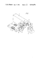
- FIG. 1 illustrates a simplified perspective view of a preferred embodiment of the invention with certain details left out, in particular some parts of protective coverings applied to the components of the plant, and
- FIG. 2 a front view of the pressing chamber of the plant and a pressing plate displaceable therein and carrying a pattern board immediately before its being picked up by means of one of the above mentioned two carriages.
- the plant in FIG. 1 comprises an apparatus 1, known per se (see for example, U.S. Pat. No. 3,008,199 mentioned above), having a pressing chamber 2 with two associated pressing plates 3, 3a, one of which, 3a, however, is hidden within the chamber while the other one, 3, is pulled free thereform with a view to changing the pattern board 4 used so far. Subsequently, when pressing plate 3 is hidden, pressing plate 3a is free so that used pattern board 4a can be changed (as shown in FIG. 2).
- the plant further comprises a likewise known casting bed or conveyor 5 on which the mould parts 6 successively produced in the pressing chamber are lined up to form a stepwise advanced casting mould coming out from a gate in the front wall 7 of the apparatus 1, and a preferably heated storage 8 for pattern boards 4 and 4a grouped in pairs and intended for their respective one of said two pressing plates 3, 3a.
- the side of the apparatus 1 that faces the storage 8 supports an upper guiding rail 9 and a lower guiding rail 10 for a frameshaped carriage 11 movable parallel to the axis of the pressing chamber 2, and a fully analogous carriage 12 is analogously displeaceably suspended on the opposite side of the apparatus 1.
- both carriages 11 and 12 are in lateral alignment with the pressing plate 3, the pattern board of which is to be changed by transference of the used pattern board to carriage 12 and the transference of a new pattern board from carriage 11.
- the position of the pressing plate 3 and thus also the positions of the carriages in this exchange situation may vary within certain limits and the carriages 11 and 12 are, moreover, movable to a loading station (carriage 11) and a delivery station (carriage 12), respectively after transference is completed.
- said stations are illustrated as being coincident with the exchange positions, but this is normally not the case because it is usually desired to have free accessibility to the space in front of the pressing chamber 2 with a view to inspection of the newly formed mould parts and insertion of cores, if needed.
- a conveyor in the form of a trolley 13 is arranged between the storage 8 and the carriage 11, said trolley 13 travelling on floor rails 14 and thus easily moved from a position laterally opposite the set of pattern boards 4, 4a to be selected from the storage to a position laterally opposite the carriage 11 when in its loading position.
- a similar conveyor or trolley 15 may be arranged to receive the exchanged pattern boards from the carriage 12.
- FIG. 2 shows the pressing plate 3a which is hidden in FIG. 1 after it has been moved out to occupy the position which pressing plate 3 occupies in FIG. 1, and on its forward facing side carries a pattern board 4a to be changed.
- This pattern board 4a is suspended so as to be laterally displaceable on a horizontal series of rollers 16 and is under normal use fastened to the pressing plate by means of ordinary releasable locks, not shown on the drawings.
- the carriage 12 serving to pick up the pattern board 4a runs on the rails 9 and 10 on which it has been moved into a position laterally opposite the pressing plate 3a and a slide 18 displaceable on horizontal guides 19 in the carriage 12 is shifted laterally by a suitable means (not shown) to a position in which a pair of rails 20 and 21 on the slide 18 extends to or approximately to the adjacent lateral edge of the pressing plate 3a.
- the rail 20 is a pattern carrier with rollers 22 positioned in alignment with the rollers 16 of the pressing plate, while the rail 21 is a guide rail for gripping device 23 with jaws 34. Jaws 34 are suitably operated and in the illustrated situation have seized a guide pin 24 on the pattern board 4a.
- a similar guide pin 24' is located at the opposite edge of the pattern board to cooperate with a corresponding gripping device belonging to the carriage 11. This carriage may be constructed quite similar to the carriage 12 and is therefore not shown in detail.
- the slide 18 comprises a rigid arm 25 which by the displacement of the slide 18 by the suitable means (not shown) is moved between the position shown in unbroken lines and the withdrawn position shown in dotted lines.
- the arm 25 is pivotally connected with a linkage 26 of fixed length and with a hydraulic pneumatic cylinder 30 having a piston rod 32 forming a variable length linkage 27.
- Said two linkages 26 and 27 are further respectively pivotally connected with the lower end and with an intermediate point of a third linkage 28 the upper end of which is pivotally connected with the gripping device 23.
- gripping device 23 On shortening the linkage 27 by withdrawing piston rod 32 into cylinder 30, gripping device 23 will consequently be pulled to the right on the guide rail 21 and will in its end position have shifted the pattern board 4a on to the carrier rail 20 from rollers 16 of pressing plate 3a. Pattern board 4a together with the guide rail 21 will then be pulled into the carriage 12 by the reverse movement of the slide 18 such that the carriage 12 may now be moved on the rails 9 and 10 to leave the exchange position.
- the only obligation upon the operator is to select the desired pattern boards from the storage 8 and to record the required number of mould parts in the control system which subsequently takes over the responsibility for effecting the pattern board changing at the proper time and in an accurate manner, inter alia in such a manner that the mould parts production is resumed only after the "new" pattern board or boards have been locked in correct position.
- either of the carriages 11 and 12 may have one, two or possibly more slides 18 with associate carrier and guide rails 20, 21 etc. adapted to manage at least one pair of associated pattern boards 4, 4a.
- FIG. 1, which shows two pattern boards represents diagramatically a carriage having two slides 18 for moving separate pattern boards successively, while the carriage shown in FIG. 2 has only a single slide 18.
Applications Claiming Priority (2)
| Application Number | Priority Date | Filing Date | Title |
|---|---|---|---|
| DK078381A DK159600C (da) | 1981-02-20 | 1981-02-20 | Anlaeg til fremstilling af lodret delte stoebeforme bestaaende af kasseloese formparter og med udstyr til modelpladeskift. |
| DK783/81 | 1981-02-20 |
Related Parent Applications (1)
| Application Number | Title | Priority Date | Filing Date |
|---|---|---|---|
| US06347285 Continuation | 1982-02-09 |
Publications (1)
| Publication Number | Publication Date |
|---|---|
| US4541476A true US4541476A (en) | 1985-09-17 |
Family
ID=8097506
Family Applications (1)
| Application Number | Title | Priority Date | Filing Date |
|---|---|---|---|
| US06/632,275 Expired - Lifetime US4541476A (en) | 1981-02-20 | 1984-07-20 | Plant for the production of vertically divided flaskless casting moulds and including equipment for pattern board exchange |
Country Status (10)
| Country | Link |
|---|---|
| US (1) | US4541476A (de) |
| EP (1) | EP0059551B1 (de) |
| JP (1) | JPS6023901B2 (de) |
| DD (1) | DD202113A5 (de) |
| DE (1) | DE3263218D1 (de) |
| DK (1) | DK159600C (de) |
| ES (1) | ES8301708A1 (de) |
| PL (1) | PL235138A1 (de) |
| SU (1) | SU1087055A3 (de) |
| ZA (1) | ZA821045B (de) |
Cited By (7)
| Publication number | Priority date | Publication date | Assignee | Title |
|---|---|---|---|---|
| US4678021A (en) * | 1984-09-10 | 1987-07-07 | Dansk Industri Syndikat A/S | Method and an apparatus for replacing pattern plates in a moulding system |
| US20070151694A1 (en) * | 2003-12-18 | 2007-07-05 | Minoru Hirata | Method and apparatus for molding an upper and a lower mold having no flask, and a method for replacing a match plate used therefor |
| US20070175607A1 (en) * | 2004-03-18 | 2007-08-02 | Sintokogio Ltd. | Method and apparatus for molding an upper and a lower mold having no flask |
| US20090020255A1 (en) * | 2005-05-06 | 2009-01-22 | Minoru Hirata | Method of changing a match plate in a flaskless molding apparatus for an upper mold and a lower mold |
| WO2009155916A1 (en) * | 2008-06-27 | 2009-12-30 | Disa Industries A/S | Moulding chamber arrangement for a mould-string casting plant and casting plant comprising such a moulding chamber arrangement |
| US10173259B2 (en) | 2013-05-21 | 2019-01-08 | Loramendi, S. Coop. | Machine for producing sand moulds |
| US11660664B2 (en) | 2018-06-15 | 2023-05-30 | Sintokogio, Ltd. | Mold molding apparatus and method for controlling mold molding apparatus |
Families Citing this family (1)
| Publication number | Priority date | Publication date | Assignee | Title |
|---|---|---|---|---|
| DK159598C (da) * | 1983-04-18 | 1991-04-15 | Dansk Ind Syndikat | Manoevreringsapparat til brug i stoeberianlaeg |
Citations (4)
| Publication number | Priority date | Publication date | Assignee | Title |
|---|---|---|---|---|
| US3008199A (en) * | 1957-08-30 | 1961-11-14 | Jeppesen Vagn Aage | Method of producing casting molds and a plant for carrying out the said method |
| US3901304A (en) * | 1971-09-27 | 1975-08-26 | Dansk Ind Syndikat | Truck to be used when changing pattern boards in automatic mould part producing machines |
| US3967672A (en) * | 1974-06-26 | 1976-07-06 | Wallwork C M G | Making foundry moulds |
| SU531632A1 (ru) * | 1975-01-30 | 1976-10-15 | Специализированное Проектное И Конструкторско-Технологическое Бюро Литейного И Кузнечного Производств "Стройдормаш" | Устройство дл смены модельной оснастки в формовочной машине |
Family Cites Families (4)
| Publication number | Priority date | Publication date | Assignee | Title |
|---|---|---|---|---|
| DE1030526B (de) * | 1957-02-27 | 1958-05-22 | Graue G M B H | Einrichtung zum automatischen Auswechseln von Modellplatten bei selbsttaetig arbeitenden Giesserei-Fliessbandanlagen |
| FR1387537A (fr) * | 1964-02-28 | 1965-01-29 | Giesserei Und Maschb Veb | Dispositif pour changer automatiquement les plaques modèles sur des machines à mouler de fonderie |
| FR2153534A7 (de) * | 1971-09-14 | 1973-05-04 | Broussaud Et Ses Fils | |
| DD145236A1 (de) * | 1979-08-03 | 1980-12-03 | Horst Geissler | Vorrichtung zum wechseln von modellplatten |
-
1981
- 1981-02-20 DK DK078381A patent/DK159600C/da not_active IP Right Cessation
-
1982
- 1982-02-16 DE DE8282300780T patent/DE3263218D1/de not_active Expired
- 1982-02-16 EP EP82300780A patent/EP0059551B1/de not_active Expired
- 1982-02-17 ZA ZA821045A patent/ZA821045B/xx unknown
- 1982-02-18 PL PL23513882A patent/PL235138A1/xx unknown
- 1982-02-19 JP JP57024631A patent/JPS6023901B2/ja not_active Expired
- 1982-02-19 SU SU823398236A patent/SU1087055A3/ru active
- 1982-02-19 ES ES509750A patent/ES8301708A1/es not_active Expired
- 1982-02-19 DD DD82237546A patent/DD202113A5/de unknown
-
1984
- 1984-07-20 US US06/632,275 patent/US4541476A/en not_active Expired - Lifetime
Patent Citations (4)
| Publication number | Priority date | Publication date | Assignee | Title |
|---|---|---|---|---|
| US3008199A (en) * | 1957-08-30 | 1961-11-14 | Jeppesen Vagn Aage | Method of producing casting molds and a plant for carrying out the said method |
| US3901304A (en) * | 1971-09-27 | 1975-08-26 | Dansk Ind Syndikat | Truck to be used when changing pattern boards in automatic mould part producing machines |
| US3967672A (en) * | 1974-06-26 | 1976-07-06 | Wallwork C M G | Making foundry moulds |
| SU531632A1 (ru) * | 1975-01-30 | 1976-10-15 | Специализированное Проектное И Конструкторско-Технологическое Бюро Литейного И Кузнечного Производств "Стройдормаш" | Устройство дл смены модельной оснастки в формовочной машине |
Cited By (11)
| Publication number | Priority date | Publication date | Assignee | Title |
|---|---|---|---|---|
| US4678021A (en) * | 1984-09-10 | 1987-07-07 | Dansk Industri Syndikat A/S | Method and an apparatus for replacing pattern plates in a moulding system |
| US20070151694A1 (en) * | 2003-12-18 | 2007-07-05 | Minoru Hirata | Method and apparatus for molding an upper and a lower mold having no flask, and a method for replacing a match plate used therefor |
| US7654302B2 (en) * | 2003-12-18 | 2010-02-02 | Sintokogio, Ltd. | Method and apparatus for molding an upper and a lower mold having no flask, and a method for replacing a match plate used therefor |
| US20070175607A1 (en) * | 2004-03-18 | 2007-08-02 | Sintokogio Ltd. | Method and apparatus for molding an upper and a lower mold having no flask |
| US7654303B2 (en) * | 2004-03-18 | 2010-02-02 | Sintokogio, Ltd. | Method and apparatus for molding an upper and a lower mold having no flask |
| US20090020255A1 (en) * | 2005-05-06 | 2009-01-22 | Minoru Hirata | Method of changing a match plate in a flaskless molding apparatus for an upper mold and a lower mold |
| US7757744B2 (en) * | 2005-05-06 | 2010-07-20 | Sintokogio, Ltd. | Method of changing a match plate in a flaskless molding apparatus for an upper mold and a lower mold |
| KR101110929B1 (ko) * | 2005-05-06 | 2012-03-15 | 신토고교 가부시키가이샤 | 주형틀없는 상?하 주형의 조형장치에서의 매치 플레이트의교환방법 |
| WO2009155916A1 (en) * | 2008-06-27 | 2009-12-30 | Disa Industries A/S | Moulding chamber arrangement for a mould-string casting plant and casting plant comprising such a moulding chamber arrangement |
| US10173259B2 (en) | 2013-05-21 | 2019-01-08 | Loramendi, S. Coop. | Machine for producing sand moulds |
| US11660664B2 (en) | 2018-06-15 | 2023-05-30 | Sintokogio, Ltd. | Mold molding apparatus and method for controlling mold molding apparatus |
Also Published As
| Publication number | Publication date |
|---|---|
| JPS6023901B2 (ja) | 1985-06-10 |
| DE3263218D1 (en) | 1985-05-30 |
| JPS57152348A (en) | 1982-09-20 |
| DK159600B (da) | 1990-11-05 |
| EP0059551A1 (de) | 1982-09-08 |
| DD202113A5 (de) | 1983-08-31 |
| EP0059551B1 (de) | 1985-04-24 |
| SU1087055A3 (ru) | 1984-04-15 |
| DK159600C (da) | 1991-04-29 |
| PL235138A1 (de) | 1982-09-27 |
| ES509750A0 (es) | 1983-01-16 |
| ES8301708A1 (es) | 1983-01-16 |
| DK78381A (da) | 1982-08-21 |
| ZA821045B (en) | 1983-01-26 |
Similar Documents
| Publication | Publication Date | Title |
|---|---|---|
| US4518338A (en) | Injection molding machine with mold changing and mold preconditioning device | |
| US4541476A (en) | Plant for the production of vertically divided flaskless casting moulds and including equipment for pattern board exchange | |
| JPS58222827A (ja) | 射出成形用金型の自動交換装置 | |
| US5256053A (en) | Brick press | |
| JP4174882B2 (ja) | コンクリートブロック成形機の型枠交換方法及びその装置 | |
| US4737095A (en) | Component changing apparatus serving a group of injection molding machines | |
| US4711292A (en) | Core and shell shooter | |
| US4840218A (en) | Automatic matchplate molding system | |
| US2631342A (en) | Molding and casting apparatus | |
| CZ259194A3 (en) | Apparatus for producing ring-shaped or tubular elements from concrete | |
| US4890664A (en) | Automatic matchplate molding system | |
| US5022512A (en) | Automatic matchplate molding system | |
| US5269364A (en) | Low pressure die casting apparatus | |
| US4673022A (en) | Arrangement for the changing of implements in foundry machines | |
| US5076342A (en) | Procedure and apparatus for changing of core masks at a core setting apparatus for an automatic core making system | |
| DE19540866B4 (de) | Formanlage mit Form- und Handhabungsfunktion | |
| US972108A (en) | Pipe-foundry plant. | |
| US5072777A (en) | Press for pressing of molds | |
| US2960735A (en) | Foundry system | |
| US5234331A (en) | Automated pipe making machine | |
| DE4430469A1 (de) | Vorrichtung zum Verbringen von Steinformlingen von einer Formpresse auf einen Härtewagen | |
| JPS58145316A (ja) | プレス金型自動交換装置 | |
| EP0406668B1 (de) | Presse mit einer gleitend gestützten Pressekammer zum Herstellen von Formelementen | |
| US4977944A (en) | Core blowing machine | |
| US2825103A (en) | Article-handling system |
Legal Events
| Date | Code | Title | Description |
|---|---|---|---|
| STCF | Information on status: patent grant |
Free format text: PATENTED CASE |
|
| FEPP | Fee payment procedure |
Free format text: PAYOR NUMBER ASSIGNED (ORIGINAL EVENT CODE: ASPN); ENTITY STATUS OF PATENT OWNER: LARGE ENTITY |
|
| FPAY | Fee payment |
Year of fee payment: 4 |
|
| FEPP | Fee payment procedure |
Free format text: PAYER NUMBER DE-ASSIGNED (ORIGINAL EVENT CODE: RMPN); ENTITY STATUS OF PATENT OWNER: LARGE ENTITY Free format text: PAYOR NUMBER ASSIGNED (ORIGINAL EVENT CODE: ASPN); ENTITY STATUS OF PATENT OWNER: LARGE ENTITY |
|
| FPAY | Fee payment |
Year of fee payment: 8 |
|
| FPAY | Fee payment |
Year of fee payment: 12 |