US4532086A - Packing made of one-piece layers - Google Patents
Packing made of one-piece layers Download PDFInfo
- Publication number
- US4532086A US4532086A US06/397,435 US39743582A US4532086A US 4532086 A US4532086 A US 4532086A US 39743582 A US39743582 A US 39743582A US 4532086 A US4532086 A US 4532086A
- Authority
- US
- United States
- Prior art keywords
- packing
- layer
- deflecting
- bridges
- set forth
- Prior art date
- Legal status (The legal status is an assumption and is not a legal conclusion. Google has not performed a legal analysis and makes no representation as to the accuracy of the status listed.)
- Expired - Lifetime
Links
Images


Classifications
-
- B—PERFORMING OPERATIONS; TRANSPORTING
- B01—PHYSICAL OR CHEMICAL PROCESSES OR APPARATUS IN GENERAL
- B01D—SEPARATION
- B01D3/00—Distillation or related exchange processes in which liquids are contacted with gaseous media, e.g. stripping
- B01D3/14—Fractional distillation or use of a fractionation or rectification column
- B01D3/16—Fractionating columns in which vapour bubbles through liquid
- B01D3/24—Fractionating columns in which vapour bubbles through liquid with sloping plates or elements mounted stepwise
-
- B—PERFORMING OPERATIONS; TRANSPORTING
- B01—PHYSICAL OR CHEMICAL PROCESSES OR APPARATUS IN GENERAL
- B01F—MIXING, e.g. DISSOLVING, EMULSIFYING OR DISPERSING
- B01F25/00—Flow mixers; Mixers for falling materials, e.g. solid particles
- B01F25/40—Static mixers
- B01F25/42—Static mixers in which the mixing is affected by moving the components jointly in changing directions, e.g. in tubes provided with baffles or obstructions
- B01F25/43—Mixing tubes, e.g. wherein the material is moved in a radial or partly reversed direction
- B01F25/432—Mixing tubes, e.g. wherein the material is moved in a radial or partly reversed direction with means for dividing the material flow into separate sub-flows and for repositioning and recombining these sub-flows; Cross-mixing, e.g. conducting the outer layer of the material nearer to the axis of the tube or vice-versa
-
- B—PERFORMING OPERATIONS; TRANSPORTING
- B01—PHYSICAL OR CHEMICAL PROCESSES OR APPARATUS IN GENERAL
- B01J—CHEMICAL OR PHYSICAL PROCESSES, e.g. CATALYSIS OR COLLOID CHEMISTRY; THEIR RELEVANT APPARATUS
- B01J19/00—Chemical, physical or physico-chemical processes in general; Their relevant apparatus
- B01J19/32—Packing elements in the form of grids or built-up elements for forming a unit or module inside the apparatus for mass or heat transfer
-
- F—MECHANICAL ENGINEERING; LIGHTING; HEATING; WEAPONS; BLASTING
- F28—HEAT EXCHANGE IN GENERAL
- F28F—DETAILS OF HEAT-EXCHANGE AND HEAT-TRANSFER APPARATUS, OF GENERAL APPLICATION
- F28F25/00—Component parts of trickle coolers
- F28F25/02—Component parts of trickle coolers for distributing, circulating, and accumulating liquid
- F28F25/08—Splashing boards or grids, e.g. for converting liquid sprays into liquid films; Elements or beds for increasing the area of the contact surface
-
- B—PERFORMING OPERATIONS; TRANSPORTING
- B01—PHYSICAL OR CHEMICAL PROCESSES OR APPARATUS IN GENERAL
- B01J—CHEMICAL OR PHYSICAL PROCESSES, e.g. CATALYSIS OR COLLOID CHEMISTRY; THEIR RELEVANT APPARATUS
- B01J2219/00—Chemical, physical or physico-chemical processes in general; Their relevant apparatus
- B01J2219/32—Details relating to packing elements in the form of grids or built-up elements for forming a unit of module inside the apparatus for mass or heat transfer
- B01J2219/322—Basic shape of the elements
- B01J2219/32203—Sheets
- B01J2219/32206—Flat sheets
-
- B—PERFORMING OPERATIONS; TRANSPORTING
- B01—PHYSICAL OR CHEMICAL PROCESSES OR APPARATUS IN GENERAL
- B01J—CHEMICAL OR PHYSICAL PROCESSES, e.g. CATALYSIS OR COLLOID CHEMISTRY; THEIR RELEVANT APPARATUS
- B01J2219/00—Chemical, physical or physico-chemical processes in general; Their relevant apparatus
- B01J2219/32—Details relating to packing elements in the form of grids or built-up elements for forming a unit of module inside the apparatus for mass or heat transfer
- B01J2219/322—Basic shape of the elements
- B01J2219/32203—Sheets
- B01J2219/32213—Plurality of essentially parallel sheets
-
- B—PERFORMING OPERATIONS; TRANSPORTING
- B01—PHYSICAL OR CHEMICAL PROCESSES OR APPARATUS IN GENERAL
- B01J—CHEMICAL OR PHYSICAL PROCESSES, e.g. CATALYSIS OR COLLOID CHEMISTRY; THEIR RELEVANT APPARATUS
- B01J2219/00—Chemical, physical or physico-chemical processes in general; Their relevant apparatus
- B01J2219/32—Details relating to packing elements in the form of grids or built-up elements for forming a unit of module inside the apparatus for mass or heat transfer
- B01J2219/322—Basic shape of the elements
- B01J2219/32203—Sheets
- B01J2219/32224—Sheets characterised by the orientation of the sheet
- B01J2219/32234—Inclined orientation
-
- B—PERFORMING OPERATIONS; TRANSPORTING
- B01—PHYSICAL OR CHEMICAL PROCESSES OR APPARATUS IN GENERAL
- B01J—CHEMICAL OR PHYSICAL PROCESSES, e.g. CATALYSIS OR COLLOID CHEMISTRY; THEIR RELEVANT APPARATUS
- B01J2219/00—Chemical, physical or physico-chemical processes in general; Their relevant apparatus
- B01J2219/32—Details relating to packing elements in the form of grids or built-up elements for forming a unit of module inside the apparatus for mass or heat transfer
- B01J2219/322—Basic shape of the elements
- B01J2219/32286—Grids or lattices
-
- F—MECHANICAL ENGINEERING; LIGHTING; HEATING; WEAPONS; BLASTING
- F28—HEAT EXCHANGE IN GENERAL
- F28D—HEAT-EXCHANGE APPARATUS, NOT PROVIDED FOR IN ANOTHER SUBCLASS, IN WHICH THE HEAT-EXCHANGE MEDIA DO NOT COME INTO DIRECT CONTACT
- F28D21/00—Heat-exchange apparatus not covered by any of the groups F28D1/00 - F28D20/00
- F28D2021/0019—Other heat exchangers for particular applications; Heat exchange systems not otherwise provided for
- F28D2021/0052—Other heat exchangers for particular applications; Heat exchange systems not otherwise provided for for mixers
-
- Y—GENERAL TAGGING OF NEW TECHNOLOGICAL DEVELOPMENTS; GENERAL TAGGING OF CROSS-SECTIONAL TECHNOLOGIES SPANNING OVER SEVERAL SECTIONS OF THE IPC; TECHNICAL SUBJECTS COVERED BY FORMER USPC CROSS-REFERENCE ART COLLECTIONS [XRACs] AND DIGESTS
- Y10—TECHNICAL SUBJECTS COVERED BY FORMER USPC
- Y10S—TECHNICAL SUBJECTS COVERED BY FORMER USPC CROSS-REFERENCE ART COLLECTIONS [XRACs] AND DIGESTS
- Y10S261/00—Gas and liquid contact apparatus
- Y10S261/72—Packing elements
-
- Y—GENERAL TAGGING OF NEW TECHNOLOGICAL DEVELOPMENTS; GENERAL TAGGING OF CROSS-SECTIONAL TECHNOLOGIES SPANNING OVER SEVERAL SECTIONS OF THE IPC; TECHNICAL SUBJECTS COVERED BY FORMER USPC CROSS-REFERENCE ART COLLECTIONS [XRACs] AND DIGESTS
- Y10—TECHNICAL SUBJECTS COVERED BY FORMER USPC
- Y10T—TECHNICAL SUBJECTS COVERED BY FORMER US CLASSIFICATION
- Y10T428/00—Stock material or miscellaneous articles
- Y10T428/24—Structurally defined web or sheet [e.g., overall dimension, etc.]
- Y10T428/24149—Honeycomb-like
-
- Y—GENERAL TAGGING OF NEW TECHNOLOGICAL DEVELOPMENTS; GENERAL TAGGING OF CROSS-SECTIONAL TECHNOLOGIES SPANNING OVER SEVERAL SECTIONS OF THE IPC; TECHNICAL SUBJECTS COVERED BY FORMER USPC CROSS-REFERENCE ART COLLECTIONS [XRACs] AND DIGESTS
- Y10—TECHNICAL SUBJECTS COVERED BY FORMER USPC
- Y10T—TECHNICAL SUBJECTS COVERED BY FORMER US CLASSIFICATION
- Y10T428/00—Stock material or miscellaneous articles
- Y10T428/24—Structurally defined web or sheet [e.g., overall dimension, etc.]
- Y10T428/24479—Structurally defined web or sheet [e.g., overall dimension, etc.] including variation in thickness
- Y10T428/24562—Interlaminar spaces
Definitions
- This invention relates to a packing made of one-piece layers and a process of making the packing.
- various types of packings have been known for use in mass transfer, direct heat exchange and mixing.
- various types of packings have been used in static mixers such as described in German A.S. No. 23 28 795 and 25 22 106.
- the function of the packings in these mixers is to provide a homogeneous mixing of two or more cocurrent flows, that is, to insure good mixing of the end product over the whole flow cross-section at all quantity and viscosity ratios of the components required to be mixed.
- the packings When used in mass transfer processes, the packings are flowed through in counter-current by the phases concerned in the mass transfer.
- the various surfaces of the packings serve as support surfaces for a liquid phase which trickles down as a film under gravity and with which, in the case of a gas-liquid process, for instance rectification, a gas phase filling up the various gaps in the packing in counter-current to the liquid phase is brought into surface contact or with which, in the case of extraction columns, a second liquid phase is brought into surface contact.
- German A.S. No. 23 28 795 describes packings which are formed of comb-like plates which are pushed together in the shape of a cross.
- German A.S. No. 25 22 106 describes packings which consist of joined-together discrete elements in the form of "Spanish riders". In each case, the packings require special stamping tools for each diameter.
- the invention provides a packing which is comprised of a plurality of vertically disposed parallel layers.
- Each layer has a plurality of inclined parallel deflecting surfaces and at least one bridge at one end of the layer connecting the deflecting surfaces together.
- the deflecting surfaces of one layer are disposed in criss-crossing relation to the deflecting surfaces of the adjacent layer so as to define crossing flow channels.
- each layer of the packing is made from a flat one-piece body which can be stamped or punched.
- the one-piece body which may be made of sheet metal or other like foil material is stamped or punched to form deflecting surfaces which can be bent out of the plane of the body with connecting bridges of material being left between the discrete deflecting surfaces.
- the individual layers can be placed in contiguous relationship with one another so that the deflecting surfaces of the adjacent layers criss-cross. By placing layers of different lengths in side-by-side relationship, packings of any required cross-section can be provided.
- each layer can be injected molded. Subsequently, such injected molded layers can be placed in contiguous relation to form a packing.
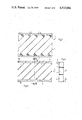
- FIG. 1 illustrates a perspective view of three layers of a packing constructed in accordance with the invention
- FIG. 2 illustrates a plan view of a one-piece body from which a packing layer can be fabricated in accordance with the invention
- FIG. 3 illustrates a view of the body of FIG. 2 with deflecting surfaces bent out of the plane of the body
- FIG. 4 illustrates a view taken on line IV--IV of FIG. 3;
- FIG. 5 illustrates a plan view of a stamped body for forming a modified packing layer in accordance with the invention
- FIG. 6 illustrates a view of the body of FIG. 5 with deflecting surfaces bent outwardly
- FIG. 7 illustrates a view taken on line VI--VI of FIG. 6;
- FIG. 8 illustrates a plan view of a further modified one-piece body for forming a packing layer in accordance with the invention
- FIG. 9 illustrates a view of the body of FIG. 8 with deflecting surfaces bent outwardly
- FIG. 10 illustrates a view taken on line IX--IX of FIG. 9;
- FIG. 11 illustrates a plan view of a further modified one-piece body for forming a packing layer in accordance with the invention
- FIG. 12 illustrates a view of the body of FIG. 11 with deflecting surfaces bent outwardly
- FIG. 13 illustrates a view taken on line XII--XII of FIG. 12;
- FIG. 14 illustrates a view similar to FIG. 11 of a further modified body for forming a packing layer in accordance with the invention
- FIG. 15 illustrates a view of the body of FIG. 14 with the deflecting surfaces bent outwardly
- FIG. 16 illustrates a view taken on line XV--XV of FIG. 15;
- FIG. 17 illustrates a plan view of a further modified body for forming a packing layer in accordance with the invention
- FIG. 18 illustrates a view of the body of FIG. 17 with deflecting surfaces bent outwardly
- FIG. 19 illustrates a view taken on line XIX--XIX of FIG. 18.
- the packing is composed of a plurality of vertically disposed parallel layers 2. For example, only 3 of the layers 2 are shown for simplicity with the contours of the layers indicated by contour lines U.
- the packing can be used for any suitable purposes, for example in exchange columns, for example for mass exchange or for heat exchange purposes.
- each layer 2 has a plurality of inclined parallel deflecting surfaces 1 and a pair of bridges 3 at the top and bottom ends of each layer 2 which connect the deflecting surfaces 1 together.
- the deflecting surfaces 1 are inclined relative to a vertical axis, for example the axis of an exchange column.
- the deflecting surfaces 1 of each layer 2 are disposed in criss-crossing relation to the deflecting surfaces 1 of an adjacent continuous layer 2 to form criss-cross flow channels.
- each layer 2 of the packing can be made from a flat one piece body, for example of foil like or sheet like material such as sheet metal.
- a body is stamped or punched so as to form parallel deflecting surfaces 1 which may or may not be perforated and/or roughened and/or fluted.
- bridges 3 are formed along the top and bottom of the sheet metal body with the surfaces 1 connected at opposite ends to the respective bridges 3 in banister-fashion via triangular connecting pieces 3a.
- the deflecting surfaces 1 extend between the bridges 3 and are connected at the diagonally opposite corners to the bridges 3.
- the tips of the surfaces 1 are severed during punching in order not to project from the plane of the body after a bending operation. The resultant gaps or spaces which arise at this time are shown in hatched lines.
- the deflecting surfaces 1 are bent relative to the two bridges 3 out of the plane of the body. As indicated in FIG. 4, the bridges are also displaced into separate parallel planes.
- the various layers 2 are placed in contiguous relation with each other so that the deflecting surfaces 1 of adjacent layers criss-cross one another. Thereafter, the contacting bridges 3 are secured to each other, for example by spot welding.
- the one-piece body may be stamped so that the deflecting surfaces 1' are connected to the two bridges 3' at opposite ends and along the same edge via connecting pieces 3a'.
- the tips of the deflecting surfaces 1' are severed at only one end, as indicated by cross-hatching. Further, as indicated in FIG. 6, the deflecting surfaces 1 are bent out of the plane of both bridges 3' so that the bridges 3' remain in co-planar relation as indicated in FIG. 7.
- a one-piece body of sheet metal may be punched so as to form not only deflecting surfaces 1" but also a plurality of parallel strips 1a which are angularly disposed between the bridges 3'. As indicated, each deflecting surface 1 is connected along one edge with a respective strip 1a.
- the deflecting surfaces 1" may be bent out of the plane of the sheet metal body in alternating fashion. In this way, the bridges 3" and strips 1a are centrally located between two series of deflecting surfaces 1".
- FIG. 8 illustrates bending lines 4 about which the deflecting surfaces 1" are bent relative to the strips 1a.
- a flat one-piece body may be formed with three bridges 13a, 13b, 13c with each deflecting surface having a pair of sections 11a, 11b disposed about the central bridge 13b.
- the body is formed with a plurality of parallel strips which are formed with sections 12a, 12b to connect each deflecting surface section 11a, 11b between two of the bridges 13a, 13b, 13c.
- the deflecting surface sections 11a, 11b are bent out of the plane of the body so that the bridges 13a, 13b, 13c are coplanar.
- a one-piece body 10' may have the deflecting surface sections 11a', 11b' angularly disposed relative to each other.
- the various deflecting surface sections 11a', 11b' define rows of angularly disposed deflecting surfaces which are vertically offset with respect to each other.
- each deflecting surface 1 may be formed with a bendable connecting lug 5 along at least one edge. These lugs 5 may be punched out from the adjacent deflecting surfaces during forming. As indicated in FIGS. 18 and 19, the lugs 5 are bent so as to be parallel to the bridges 3 so as to provide an additional connection point between the adjacent layers 2.
- the deflecting surfaces may also be provided with jagged edges on the narrow sides and/or the connecting bridges may have jagged free edges to aid in insuring a uniform discharge of a descending liquid phase on the packing.
- a flat sheet like body of any one of the above described embodiments is first formed so as to have at least two parallel spaced apart bridges and a plurality of bendable parallel deflecting surfaces angularly disposed between the bridges. Thereafter, the deflecting surfaces are bent out of the plane of the bridges for instance by 90°. In the embodiment where the deflecting surfaces are formed with the bendable lugs, each lug is bent relative to the deflecting surface into parallel relation with the bridges.
- the packing layers can be injection molded.
- the layers can be made, for example of plastics.
- the layers may be continously formed from a relative long strip of flat material and cut to the appropriate length for forming for instance a packing of cylindrical shape.
- a packing body for a column may also be formed by arranging the layers such, that their bridges come into a position parallel to the axis of the column.
- the invention thus provides a packing which is composed of layers which form criss-crossing flow channels while being laterally open from one layer to the next.
- the packing can be used, for example in exchange processes such as for mass exchange and direct heat exchange and mixing purposes.
Landscapes
- Chemical & Material Sciences (AREA)
- Chemical Kinetics & Catalysis (AREA)
- Engineering & Computer Science (AREA)
- Thermal Sciences (AREA)
- Physics & Mathematics (AREA)
- Mechanical Engineering (AREA)
- Organic Chemistry (AREA)
- General Engineering & Computer Science (AREA)
- Dispersion Chemistry (AREA)
- Physical Or Chemical Processes And Apparatus (AREA)
- Gas Separation By Absorption (AREA)
- Extraction Or Liquid Replacement (AREA)
- Vaporization, Distillation, Condensation, Sublimation, And Cold Traps (AREA)
- Escalators And Moving Walkways (AREA)
- Injection Moulding Of Plastics Or The Like (AREA)
Applications Claiming Priority (2)
| Application Number | Priority Date | Filing Date | Title |
|---|---|---|---|
| CH4923/81A CH656320A5 (de) | 1981-07-30 | 1981-07-30 | Einbauelement fuer eine vorrichtung fuer stoff- und/oder direkten waermeaustausch oder mischen. |
| CH4923/81 | 1981-07-30 |
Publications (1)
| Publication Number | Publication Date |
|---|---|
| US4532086A true US4532086A (en) | 1985-07-30 |
Family
ID=4284875
Family Applications (1)
| Application Number | Title | Priority Date | Filing Date |
|---|---|---|---|
| US06/397,435 Expired - Lifetime US4532086A (en) | 1981-07-30 | 1982-07-12 | Packing made of one-piece layers |
Country Status (8)
| Country | Link |
|---|---|
| US (1) | US4532086A (de) |
| EP (1) | EP0070921B1 (de) |
| JP (1) | JPS5827635A (de) |
| AU (1) | AU550532B2 (de) |
| BR (1) | BR8204111A (de) |
| CA (1) | CA1211104A (de) |
| CH (1) | CH656320A5 (de) |
| DE (1) | DE3173371D1 (de) |
Cited By (13)
| Publication number | Priority date | Publication date | Assignee | Title |
|---|---|---|---|---|
| US4719090A (en) * | 1984-02-28 | 1988-01-12 | Ngk Insulators, Ltd. | Porous structure for fluid contact |
| US4806288A (en) * | 1987-09-23 | 1989-02-21 | Nowosinski George B | Packing elements |
| US4882130A (en) * | 1988-06-07 | 1989-11-21 | Ngk Insulators, Ltd. | Porous structure of fluid contact |
| US5326504A (en) * | 1993-08-16 | 1994-07-05 | The Boc Group, Inc. | Ordered packing |
| US5458817A (en) * | 1994-04-19 | 1995-10-17 | Lantec Products, Inc. | Folding packing and method of manufacture |
| EP0774295A1 (de) | 1995-11-17 | 1997-05-21 | Institut Francais Du Petrole | Füllkörper mit hoher Adsorptionsfähigkeit für Abgasreinigungsvorrichtung |
| US5637263A (en) * | 1994-04-19 | 1997-06-10 | Lantec Products, Inc. | Multifold packing and method of forming |
| US5865242A (en) * | 1994-05-06 | 1999-02-02 | Neri; Bruno | Modules for mass transfer and other applications and methods of use |
| US5965784A (en) * | 1995-09-12 | 1999-10-12 | Total Raffinage Distribution S.A. | Process and apparatus for extracting aromatic compounds contained in a hydrocarbon feedstock |
| US6032932A (en) * | 1998-01-27 | 2000-03-07 | Sixsmith; Richard | Packing grates for wet gas scrubber and other applications |
| US20050247700A1 (en) * | 2004-04-23 | 2005-11-10 | Eric Kochman | Heater with simultaneous hot spot and mechanical intrusion protection |
| KR101687578B1 (ko) | 2016-04-29 | 2017-01-02 | 이석룡 | 수평형 습식 스크러버의 충전물용 그레이팅 |
| CN106536082A (zh) * | 2014-06-05 | 2017-03-22 | 域流反应器技术有限公司 | 构造用于热交换的工程填料的系统和方法 |
Families Citing this family (5)
| Publication number | Priority date | Publication date | Assignee | Title |
|---|---|---|---|---|
| CH656320A5 (de) * | 1981-07-30 | 1986-06-30 | Sulzer Ag | Einbauelement fuer eine vorrichtung fuer stoff- und/oder direkten waermeaustausch oder mischen. |
| GB2195327A (en) * | 1986-09-16 | 1988-04-07 | Tuke & Bell Ltd | Fluid processing medium |
| CH676434A5 (en) * | 1988-09-14 | 1991-01-31 | Sulzer Ag | Corrugations in sheet filling elements for fluid contact - columns are bonded at numerous meeting points to resist displacement |
| DE3920123C1 (de) * | 1989-06-20 | 1990-12-20 | Alfred Innsbruck At Hupfauf | |
| US8235361B2 (en) * | 2009-02-09 | 2012-08-07 | Tribute Creations, Llc | Structured packing for a reactor |
Citations (13)
| Publication number | Priority date | Publication date | Assignee | Title |
|---|---|---|---|---|
| US1561044A (en) * | 1925-02-20 | 1925-11-10 | Clive M Alexander | Baffle tower |
| US3168432A (en) * | 1961-12-22 | 1965-02-02 | Thore M Elfving | Core material |
| US3574103A (en) * | 1968-09-06 | 1971-04-06 | Atomic Energy Commission | Laminated cellular material form |
| US3599943A (en) * | 1968-04-04 | 1971-08-17 | Carl Georg Munters | Liquid and gas contact apparatus |
| US3698440A (en) * | 1970-04-21 | 1972-10-17 | Kabel Metallwerke Ghh | Thermally insulated conduit |
| US3758372A (en) * | 1971-07-22 | 1973-09-11 | Fmc Corp | Foraminous structures |
| US3785620A (en) * | 1971-04-29 | 1974-01-15 | Sulzer Ag | Mixing apparatus and method |
| US3801419A (en) * | 1971-07-20 | 1974-04-02 | Munters Ab Carl | Corrugated sheet member with a reinforcing edge extending lengthwise of the corrugations |
| US3927165A (en) * | 1973-05-23 | 1975-12-16 | Sulzer Ag | Non-corrosive regular packing member and a method of making same |
| US4107241A (en) * | 1976-10-12 | 1978-08-15 | Raschig G.M.B.H. | Contacting arrangement for mass transfer operations |
| US4157929A (en) * | 1976-06-17 | 1979-06-12 | Sulzer Brothers Limited | Method of making a porous dimensionally stable heat-resistant and corrosion-resistant plate-like structure |
| EP0070921A1 (de) * | 1981-07-30 | 1983-02-09 | GebràDer Sulzer Aktiengesellschaft | Einbauelement für eine Vorrichtung für Stoff- und direkten Wärmeaustausch und Mischen |
| EP0070915A1 (de) * | 1981-07-30 | 1983-02-09 | GebràDer Sulzer Aktiengesellschaft | Einbauelement für eine Vorrichtung für Stoff- und direkten Wärmeaustausch und Mischen |
Family Cites Families (3)
| Publication number | Priority date | Publication date | Assignee | Title |
|---|---|---|---|---|
| JPS5651996Y2 (de) * | 1975-04-02 | 1981-12-04 | ||
| DE2910525C2 (de) * | 1979-03-17 | 1983-07-14 | Julius Montz Gmbh, 4010 Hilden | Austauschkolonnenpackung |
| DE2942481A1 (de) * | 1979-10-20 | 1981-04-30 | Bayer Ag, 5090 Leverkusen | Rieselfuellung fuer stoffaustauschkolonnen |
-
1981
- 1981-07-30 CH CH4923/81A patent/CH656320A5/de not_active IP Right Cessation
- 1981-09-04 EP EP81106949A patent/EP0070921B1/de not_active Expired
- 1981-09-04 DE DE8181106949T patent/DE3173371D1/de not_active Expired
-
1982
- 1982-07-12 US US06/397,435 patent/US4532086A/en not_active Expired - Lifetime
- 1982-07-12 JP JP57121109A patent/JPS5827635A/ja active Granted
- 1982-07-15 BR BR8204111A patent/BR8204111A/pt not_active IP Right Cessation
- 1982-07-23 CA CA000407990A patent/CA1211104A/en not_active Expired
- 1982-07-28 AU AU86492/82A patent/AU550532B2/en not_active Ceased
Patent Citations (13)
| Publication number | Priority date | Publication date | Assignee | Title |
|---|---|---|---|---|
| US1561044A (en) * | 1925-02-20 | 1925-11-10 | Clive M Alexander | Baffle tower |
| US3168432A (en) * | 1961-12-22 | 1965-02-02 | Thore M Elfving | Core material |
| US3599943A (en) * | 1968-04-04 | 1971-08-17 | Carl Georg Munters | Liquid and gas contact apparatus |
| US3574103A (en) * | 1968-09-06 | 1971-04-06 | Atomic Energy Commission | Laminated cellular material form |
| US3698440A (en) * | 1970-04-21 | 1972-10-17 | Kabel Metallwerke Ghh | Thermally insulated conduit |
| US3785620A (en) * | 1971-04-29 | 1974-01-15 | Sulzer Ag | Mixing apparatus and method |
| US3801419A (en) * | 1971-07-20 | 1974-04-02 | Munters Ab Carl | Corrugated sheet member with a reinforcing edge extending lengthwise of the corrugations |
| US3758372A (en) * | 1971-07-22 | 1973-09-11 | Fmc Corp | Foraminous structures |
| US3927165A (en) * | 1973-05-23 | 1975-12-16 | Sulzer Ag | Non-corrosive regular packing member and a method of making same |
| US4157929A (en) * | 1976-06-17 | 1979-06-12 | Sulzer Brothers Limited | Method of making a porous dimensionally stable heat-resistant and corrosion-resistant plate-like structure |
| US4107241A (en) * | 1976-10-12 | 1978-08-15 | Raschig G.M.B.H. | Contacting arrangement for mass transfer operations |
| EP0070921A1 (de) * | 1981-07-30 | 1983-02-09 | GebràDer Sulzer Aktiengesellschaft | Einbauelement für eine Vorrichtung für Stoff- und direkten Wärmeaustausch und Mischen |
| EP0070915A1 (de) * | 1981-07-30 | 1983-02-09 | GebràDer Sulzer Aktiengesellschaft | Einbauelement für eine Vorrichtung für Stoff- und direkten Wärmeaustausch und Mischen |
Cited By (13)
| Publication number | Priority date | Publication date | Assignee | Title |
|---|---|---|---|---|
| US4719090A (en) * | 1984-02-28 | 1988-01-12 | Ngk Insulators, Ltd. | Porous structure for fluid contact |
| US4806288A (en) * | 1987-09-23 | 1989-02-21 | Nowosinski George B | Packing elements |
| US4882130A (en) * | 1988-06-07 | 1989-11-21 | Ngk Insulators, Ltd. | Porous structure of fluid contact |
| US5326504A (en) * | 1993-08-16 | 1994-07-05 | The Boc Group, Inc. | Ordered packing |
| US5637263A (en) * | 1994-04-19 | 1997-06-10 | Lantec Products, Inc. | Multifold packing and method of forming |
| US5458817A (en) * | 1994-04-19 | 1995-10-17 | Lantec Products, Inc. | Folding packing and method of manufacture |
| US5865242A (en) * | 1994-05-06 | 1999-02-02 | Neri; Bruno | Modules for mass transfer and other applications and methods of use |
| US5965784A (en) * | 1995-09-12 | 1999-10-12 | Total Raffinage Distribution S.A. | Process and apparatus for extracting aromatic compounds contained in a hydrocarbon feedstock |
| EP0774295A1 (de) | 1995-11-17 | 1997-05-21 | Institut Francais Du Petrole | Füllkörper mit hoher Adsorptionsfähigkeit für Abgasreinigungsvorrichtung |
| US6032932A (en) * | 1998-01-27 | 2000-03-07 | Sixsmith; Richard | Packing grates for wet gas scrubber and other applications |
| US20050247700A1 (en) * | 2004-04-23 | 2005-11-10 | Eric Kochman | Heater with simultaneous hot spot and mechanical intrusion protection |
| CN106536082A (zh) * | 2014-06-05 | 2017-03-22 | 域流反应器技术有限公司 | 构造用于热交换的工程填料的系统和方法 |
| KR101687578B1 (ko) | 2016-04-29 | 2017-01-02 | 이석룡 | 수평형 습식 스크러버의 충전물용 그레이팅 |
Also Published As
| Publication number | Publication date |
|---|---|
| AU8649282A (en) | 1983-02-03 |
| CH656320A5 (de) | 1986-06-30 |
| EP0070921A1 (de) | 1983-02-09 |
| JPH0372341B2 (de) | 1991-11-18 |
| CA1211104A (en) | 1986-09-09 |
| EP0070921B1 (de) | 1986-01-02 |
| DE3173371D1 (en) | 1986-02-13 |
| BR8204111A (pt) | 1983-07-05 |
| JPS5827635A (ja) | 1983-02-18 |
| AU550532B2 (en) | 1986-03-27 |
Similar Documents
| Publication | Publication Date | Title |
|---|---|---|
| US4532086A (en) | Packing made of one-piece layers | |
| US4497753A (en) | Corrugated sheet packing and method of making | |
| US4497751A (en) | Zig-zag profile packing and method of making | |
| US4497752A (en) | X-Shaped packing layers and method of making | |
| US4744928A (en) | Regular packing for countercurrent mass and direct heat transfer columns | |
| US5882772A (en) | Packing element for use, in particular, in mass transfer and/or heat transfer columns or towers | |
| US4710326A (en) | Corrugated packing and methods of use | |
| US4643853A (en) | Packing element for use in mass transfer or heat transfer columns | |
| US4186159A (en) | Packing element of foil-like material for an exchange column | |
| KR940001411B1 (ko) | 교환 탑용 패킹 요소 | |
| US5632934A (en) | Packing with improved capacity for rectification systems | |
| US6578829B2 (en) | Packing for mass transfer column | |
| US4623454A (en) | Mass transfer column | |
| US4496498A (en) | Statistical packing | |
| KR900700839A (ko) | 열 및 물질 교환장치 및 그 장치의 제조 방법 | |
| US4731205A (en) | Random packing for fluid contact devices and method of preparing said packing | |
| US4366608A (en) | Method for manufacturing fluid contacting device | |
| EP0916400B1 (de) | Rektifikationskolonne unter Anwendung von strukturierte Packung zur Reduktion von Wandströmung | |
| US5411681A (en) | Random packing | |
| US5637263A (en) | Multifold packing and method of forming | |
| US4337217A (en) | Contacting arrangement for mass transfer operations and set of plates for use in said arrangement | |
| EP0033413B1 (de) | Vorrichtung für den Dampf-Flüssigkeitskontakt und Verfahren zur Herstellung von Gitterelementen zur Verwendung in einer solchen Vorrichtung | |
| US4356611A (en) | Method of fabricating vapor-liquid contact grid | |
| US20040188867A1 (en) | Structured packing with increased capacity | |
| DE2943061C2 (de) |
Legal Events
| Date | Code | Title | Description |
|---|---|---|---|
| AS | Assignment |
Owner name: SULZER BROTHERS LIMITED WINTERTHUR,SWITZERLAND A C Free format text: ASSIGNMENT OF ASSIGNORS INTEREST.;ASSIGNOR:PLUESS RAYMOND C;REEL/FRAME:004053/0802 Effective date: 19820923 |
|
| STCF | Information on status: patent grant |
Free format text: PATENTED CASE |
|
| FPAY | Fee payment |
Year of fee payment: 4 |
|
| FEPP | Fee payment procedure |
Free format text: PAYOR NUMBER ASSIGNED (ORIGINAL EVENT CODE: ASPN); ENTITY STATUS OF PATENT OWNER: LARGE ENTITY |
|
| FPAY | Fee payment |
Year of fee payment: 8 |
|
| REFU | Refund |
Free format text: REFUND PROCESSED. MAINTENANCE FEE HAS ALREADY BEEN PAID (ORIGINAL EVENT CODE: R160); ENTITY STATUS OF PATENT OWNER: LARGE ENTITY |
|
| FEPP | Fee payment procedure |
Free format text: PAYER NUMBER DE-ASSIGNED (ORIGINAL EVENT CODE: RMPN); ENTITY STATUS OF PATENT OWNER: LARGE ENTITY Free format text: PAYOR NUMBER ASSIGNED (ORIGINAL EVENT CODE: ASPN); ENTITY STATUS OF PATENT OWNER: LARGE ENTITY |
|
| FPAY | Fee payment |
Year of fee payment: 12 |