US4531063A - System for recovering wave energy and its conversion into useful energy - Google Patents
System for recovering wave energy and its conversion into useful energy Download PDFInfo
- Publication number
- US4531063A US4531063A US06/404,387 US40438782A US4531063A US 4531063 A US4531063 A US 4531063A US 40438782 A US40438782 A US 40438782A US 4531063 A US4531063 A US 4531063A
- Authority
- US
- United States
- Prior art keywords
- resilient
- lines
- energy
- accumulation
- accumulation member
- Prior art date
- Legal status (The legal status is an assumption and is not a legal conclusion. Google has not performed a legal analysis and makes no representation as to the accuracy of the status listed.)
- Expired - Fee Related
Links
Images


Classifications
-
- F—MECHANICAL ENGINEERING; LIGHTING; HEATING; WEAPONS; BLASTING
- F03—MACHINES OR ENGINES FOR LIQUIDS; WIND, SPRING, OR WEIGHT MOTORS; PRODUCING MECHANICAL POWER OR A REACTIVE PROPULSIVE THRUST, NOT OTHERWISE PROVIDED FOR
- F03B—MACHINES OR ENGINES FOR LIQUIDS
- F03B13/00—Adaptations of machines or engines for special use; Combinations of machines or engines with driving or driven apparatus; Power stations or aggregates
- F03B13/12—Adaptations of machines or engines for special use; Combinations of machines or engines with driving or driven apparatus; Power stations or aggregates characterised by using wave or tide energy
- F03B13/14—Adaptations of machines or engines for special use; Combinations of machines or engines with driving or driven apparatus; Power stations or aggregates characterised by using wave or tide energy using wave energy
- F03B13/16—Adaptations of machines or engines for special use; Combinations of machines or engines with driving or driven apparatus; Power stations or aggregates characterised by using wave or tide energy using wave energy using the relative movement between a wave-operated member, i.e. a "wom" and another member, i.e. a reaction member or "rem"
- F03B13/18—Adaptations of machines or engines for special use; Combinations of machines or engines with driving or driven apparatus; Power stations or aggregates characterised by using wave or tide energy using wave energy using the relative movement between a wave-operated member, i.e. a "wom" and another member, i.e. a reaction member or "rem" where the other member, i.e. rem is fixed, at least at one point, with respect to the sea bed or shore
- F03B13/1885—Adaptations of machines or engines for special use; Combinations of machines or engines with driving or driven apparatus; Power stations or aggregates characterised by using wave or tide energy using wave energy using the relative movement between a wave-operated member, i.e. a "wom" and another member, i.e. a reaction member or "rem" where the other member, i.e. rem is fixed, at least at one point, with respect to the sea bed or shore and the wom is tied to the rem
- F03B13/1895—Adaptations of machines or engines for special use; Combinations of machines or engines with driving or driven apparatus; Power stations or aggregates characterised by using wave or tide energy using wave energy using the relative movement between a wave-operated member, i.e. a "wom" and another member, i.e. a reaction member or "rem" where the other member, i.e. rem is fixed, at least at one point, with respect to the sea bed or shore and the wom is tied to the rem where the tie is a tension/compression member
-
- Y—GENERAL TAGGING OF NEW TECHNOLOGICAL DEVELOPMENTS; GENERAL TAGGING OF CROSS-SECTIONAL TECHNOLOGIES SPANNING OVER SEVERAL SECTIONS OF THE IPC; TECHNICAL SUBJECTS COVERED BY FORMER USPC CROSS-REFERENCE ART COLLECTIONS [XRACs] AND DIGESTS
- Y02—TECHNOLOGIES OR APPLICATIONS FOR MITIGATION OR ADAPTATION AGAINST CLIMATE CHANGE
- Y02E—REDUCTION OF GREENHOUSE GAS [GHG] EMISSIONS, RELATED TO ENERGY GENERATION, TRANSMISSION OR DISTRIBUTION
- Y02E10/00—Energy generation through renewable energy sources
- Y02E10/30—Energy from the sea, e.g. using wave energy or salinity gradient
-
- Y—GENERAL TAGGING OF NEW TECHNOLOGICAL DEVELOPMENTS; GENERAL TAGGING OF CROSS-SECTIONAL TECHNOLOGIES SPANNING OVER SEVERAL SECTIONS OF THE IPC; TECHNICAL SUBJECTS COVERED BY FORMER USPC CROSS-REFERENCE ART COLLECTIONS [XRACs] AND DIGESTS
- Y10—TECHNICAL SUBJECTS COVERED BY FORMER USPC
- Y10S—TECHNICAL SUBJECTS COVERED BY FORMER USPC CROSS-REFERENCE ART COLLECTIONS [XRACs] AND DIGESTS
- Y10S415/00—Rotary kinetic fluid motors or pumps
- Y10S415/905—Natural fluid current motor
- Y10S415/906—Natural fluid current motor having specific features for water current
Definitions
- This invention relates to a system for recovering wave energy and its conversion into useful energy.
- Many systems are known for recovering wave energy, including for example that described in British patent application No. 2,002,052.
- the hose When the buoy is struck by a wave, the hose is put into tension and its internal volume reduces, so that the incompressible fluid contained in its interior is urged outwards under pressure.
- the incompressible pressurised fluid expelled from the hose possesses energy which can be utilised in a useful manner.
- the problem to be solved is the utilisation of the energy of said incompressible fluid, and it is precisely this which is not adequately solved in the British patent application.
- a system has been found, and constitutes part of the subject matter of the invention, for converting the pressure energy of the incompressible fluid expelled from flexible hoses.
- the system according to the present invention comprises the following elements:
- the interior of the resilient lines is in communication with the accumulation member by way of a connection channel and still more preferably said connection channel is partly flexible and partly rigid, the flexible part being external to the pickup member and the rigid part being internal thereto.
- the accumulation member is generally and preferably inside the pickup member, but the system can function equally well with the accumulation member located outside the pick-up member.
- the means for converting the pressure and kinetic energy of the incompressible fluid in the system into mechanical energy are chosen preferably from turbines, in particular axial turbines, or displacement engines, in particular of variable geometry.
- Said turbines or displacement engines are preferably connected substantially into the rigid connection channel.
- a modification is possible in which the incompressible fluid flows from a high pressure accumulation member and back to the resilient lines not directly but by way of a further low pressure accumulation member.
- the means for converting the pressure and kinetic energy of the incompressible fluid into mechanical energy are connected into the communication line between the two accumulation members.
- the low pressure accumulation member discharges the incompressible fluid into the resilient lines when these are in their relaxed state, whereas these latter when in a state of tension feed the incompressible fluid into the high pressure accumulation member.
- FIG. 1 is a diagrammatic view of the system according to the present invention.
- FIG. 1A is a detail of area A in FIG. 1.
- FIG. 2 is a diagrammatic view of the connection of the hose to the pick-up member.
- FIG. 3 is a diagrammatic view of an alternative configuration of the view in FIG. 2.
- FIG. 4 is a diagrammatic view of the system for converting the wave motion into mechanical energy.
- FIG. 5 is a block diagram of the mechanical operating scheme for controlling the angle of incidence of the rotor blading.
- FIG. 6 is a diagrammatic outline of a preferred scheme of controlling the angle of incidence of the blading.
- FIG. 7 is a diagrammatic view of the resilient rotational restraint system for the turbine blades.
- FIG. 8 is a schematic diagram of another embodiment of the invention for converting mechanical energy into electrical energy.
- FIG. 9 is a diagrammatic view of a further embodiment in which the system for the conversion of energy is disposed on the sea bed.
- FIG. 10 is a schematic diagram of another embodiment for converting mechanical energy into electrical energy.
- FIG. 11 is a diagrammatic view of a system for converting the electrical energy produced by the present invention.
- FIG. 12 is a schematic diagram of an enlarged system where the energy conversion system is disposed on the sea bed.
- the system illustrated diagrammatically in FIG. 1 is constituted by a pickup member 1 which, in a preferred configuration, is of spherical shape (but can be constructed in various structural forms such as cylindrical of horizontal or vertical axis), and is kept in a submerged position at a suitable distance from the free surface of the mass of water in which it operates, and which hereinafter will be defined as "sea", by one or more resilient lines 2 (two in number in the illustrated configuration) connected to the sea bed and to suitable fixed anchorage points.
- Said anchorage points can be in the form of sunken piles 3 as in the illustrated solution, or sinker blocks, or again in the form of fixed structures which are elevated from the sea bed but are either anchored to it or are stable on it by virtue of gravity.
- Said resilient lines can also be connected to said anchorage points either directly or by way of taut structural elements (metal cables or tubes) which can be considered practically inextensible.
- the described anchorage lines are kept under tension by the effect of a buoyancy reserve situated in the pickup member itself.
- This can be attained by various types of constructions using various structural materials known to current technology, including steel, reinforced concrete and reinforced plastics, but this does not constitute a limitation to the present invention.
- the resilient connection lines are formed from a hose constructed of a material of low modulus of elasticity but high resilience 4 (such as natural and synthetic elastomers) reinforced by fibres or filaments would helically in two or more layers of opposite winding angle, so as to be embedded in the hose in a torsionally stable manner.
- Said reinforcement filaments or fibres are constructed of a material of high modulus of elasticity (such as steel, polyester, polyamide or polyaramide fibres), which can be considered practically inextensible.
- Each hose or resilient line is provided at its end with a termination 6, to which the reinforcement filaments or fibres are anchored, and to which the hose wall is connected in a water-tight manner.
- One of the terminations of each line namely the upper one in the system configuration described herein, is connected mechanically to the pickup member by means of a universal joint 7.
- Said termination also comprises an opening which communicates by way of a flexible bellows hose 8 with the hydraulic conversion circuit disposed inside the pickup member and which is described hereinafter.
- the lower termination in the described system configuration is blind and is connected mechanically to the anchorage points.
- the winding angle of the reinforcement fibres of the resilient line is less than 57.74° as indicated in the detailed FIG. 1A.
- each resilient line varies during the elongation and contraction motion
- the terminal portions of the resilient lines are formed as illustrated in FIG. 2 in order to prevent mechanical stress concentration and thus possible wear and/or fatigue of the hose structure at the structure terminations.
- the reinforcement fibres or filaments have a winding angle which varies from the value ⁇ characteristic of the hose, to the value zero. This means that they become parallel to the hose generating line at the ends to which they are anchored.
- a further reinforcement layer provided only in the terminal hose portion indicated by T is laid above the preceding and has a winding angle variable from the value ⁇ to 90°, i.e. orthogonal to the hose generating lines as indicated diagrammatically in FIG. 2, showing only two reinforcement fibres.
- This figure also diagrammatically shows the configuration of the connection of the hose 2 to the pickup member 1 by means of the terminals 6, the universal joint connection device 7 and the flexible bellows hose 8.
- the purpose of the universal joint and flexible bellows hose portion is to allow the pickup member to rotate relative to the axis of the resilient lines without subjecting the hose/termination connection to bending.
- FIG. 3 An alternative configuration of this constructional detail is shown in FIG. 3.
- the resilient line or hose 2 is connected rigidly to the pickup member 1 by means of the terminations 6, and over a portion indicated by P is contained in a tube 9 of which the thickness reduces in an outward direction and which is of flexural stiffness, and is itself rigidly fixed to the pickup member 1.
- the pickup member can rotate relative to the resilient line as this latter is prevented from assuming radii of curvature incompatible with its structural strength characteristics.
- the hose 2 comprises reinforcement fibres or filaments disposed at 0° and 90°. In the portion T external to said element, the winding angle passes to the value ⁇ as described heretofore.
- the effect of the transition of the reinforcement fibre winding angle in the portion indicated by T is that axial and transverse deformations of the hose wall allowed by the structure consisting of the reinforced fibres inclined at an angle ⁇ are progressively contained, and are prevented at the connection to the rigid terminations, at which the hose wall and reinforcement are anchored. In this manner, local stress concentrations at the edge of the termination are prevented.
- each resilient connection line is filled with a practically incompressible fluid 10, and is connected by way of the upper termination to a pressure vessel or accumulator 11 in which a suitable quantity of gas 12 is contained under pressure.
- the resilient line or hose is therefore kept under pressure. Because of the helical geometry of the reinforcement fibres, this pressure can be balanced only by a traction force which constitutes the axial reaction of this resilient connection line.
- connection lines of this type (one or more in number) together balance the buoyancy reserve of the pickup member when under static conditions.
- each connection line produces a variation in the internal volume thereof and thus movement of the fluid 10 contained therein from/to the accumulator 11
- this length variation produces a variation in the volume of gas 12 in the accumulator and thus in the pressure in the accumulator itself and in the hose.
- the effect of this pressure variation and of the variation in the geometry of the hose reinforcement is a variation in the force which the resilient connection line 2 exerts at its ends.
- connection lines which have the required interdependence between elongation and reaction force (resilient characteristic), and thus the required dynamic behaviour of the entire energy pickup system in relation to its mass characteristics and to its interaction with the wave motion fluid by virtue of its movements.
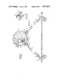
- a first preferred functional scheme shown in FIG. 4 and relating to the use of two resilient connection lines for the pickup member, but which can be extended likewise to the case of a single or more than two lines, provides for inserting into the hydraulic circuit connecting each resilient line 2 to the accumulator 11 an axial hydraulic turbine 14 which operates with a fluid stream suitably directed by static guide vanes or distributors 15 which precede and follow it whatever the direction of motion of the fluid striking it (in the reciprocating motion of the pickup member). These static guide vanes direct the motion of the fluid to the turbine in a purely axial direction (according to a preferred functional scheme).
- the turbines relative to the various resilient lines are coupled directly (in accordance with the scheme of FIG. 4) or, more generally, by rotary couplings to an electric generator 16.
- the flow of drive fluid to the turbine can be intercepted by a valve constituted by a shut-off cylinder 17 which slides axially and engages at the end of its stroke against seals 18 and 19 to close the connection between the resilient lines 2 and the rest of the circuit.
- a valve constituted by a shut-off cylinder 17 which slides axially and engages at the end of its stroke against seals 18 and 19 to close the connection between the resilient lines 2 and the rest of the circuit.
- the pickup system behaves as a rigidly constrained system, and is able to survive waves having a height and energy which are considerably greater than normal operating values.
- shut-off cylinders are opposed by a preset spring 20 and are operated by a pneumatic cylinder 21 fed by way of a circuit constituted by a first preset non-return valve 22, a suitable pneumatic buffer vessel 23, a restriction 24 and a second non-return valve 25 disposed in a circuit such as that of FIG. 4.
- the pressurised air passes through the valve 22 to the pneumatic buffer vessel 23 and thus operates the actuator cylinder 21 which acts against the preset spring 20 to close the flow of drive fluid by an extent controlled dynamically by the restriction 24 which, during that stage of the cycle in which the pressure in the pneumatic buffer vessel 23 exceeds the pressure in the accumulator 11, allows the air of the actuator cylinder circuit to pass through the non-return valve 25 to the accumulator 11.
- the restriction 24 which, during that stage of the cycle in which the pressure in the pneumatic buffer vessel 23 exceeds the pressure in the accumulator 11, allows the air of the actuator cylinder circuit to pass through the non-return valve 25 to the accumulator 11.
- a remotely controlled solenoid valve 26 allows total closure of the valves controlling the amplitude of oscillation (non-return valves) and thus allows the pickup system to be blocked.
- the energy of the pickup member and thus of the incompressible fluid is transferred alternately from the resilient lines and their respective accumulators to the turbine by controlling the angle of incidence of the turbine blading so as to attain a hydrodynamic drive action on the rotor and thus on the electric generator by virtue of the drive fluid.
- this control of the angle of incidence of the rotor blading can be effected by a mechanical operating scheme which is conventional in the field of hydraulic machine technology and which uses pneumatic, hydraulic or electromechanical operating systems based on a block diagram of the type shown by way of example in FIG. 5.
- the reference numeral 1 indicates a measuring system for the flow through the turbine both in terms of value and direction of movement.
- 2 indicates a processor for processing the instantaneous angle of incidence of the turbine blading.
- 3 indicates an actuator for setting the angle of incidence of the turbine blading.
- 4 indicates a measuring device for measuring the angle of incidence of the turbine blading.
- the flow rate through the turbine and thus the rate at which the drive fluid strikes it can be measured either by using known measuring methods for the flow of a fluid through a pipe, or by measuring the mechanical (and thus geometrical) characteristics of the resilient line as a function of time. This can be done by taking time-related measurements of the state of tension of the reinforcement fibres using an extensometer.
- the processor for processing the angle of incidence of the turbine blading can be a digital microprocessor.
- the angle of incidence of the blading is controlled in accordance with the outline diagram of FIG. 6.
- Each turbine blade 27 is hinged on an axis 28 which is normal to the axis of rotation of the rotor and passes in proximity to the leading edge of the blade, and is therefore disposed more forward (in the direction of advancement) than the hydrodynamic pressure centre 29 of the blade.
- the blade is also rotationally restrained resiliently by a spring 30 which when there is no external force keeps it in a plane normal to the axis of rotation of the rotor.
- the pressure of a motion field with an apparent velocity C (combination of the traversing velocity V and the rotational velocity U) striking the blade generates a hydrodynamic action F and thus a torsional moment about the axis of rotation 28, which is opposed by the reaction spring 30.
- FIG. 7 shows a possible constructional scheme for the resilient rotational restraint system for the turbine blades.
- Each blade 32 is rotatably connected to the rotor 33 by the bearings 34, and is also rigidly connected to the torsion bar 35, which at its other end is connected to the rotor by a demountable coupling, said torsion bar functioning as a spring.
- each resilient line is connected to a variable displacement engine 38 and thus to the accumulator 11 by the oscillation amplitude control valve 37, which has already been described (17 and associated reference numerals of the circuit of FIG. 4).
- the engine displacement is controlled by a hydraulic or electrohydraulic system 39 which processes the signal of a flow measuring device 40 and provides a suitable command to the engine displacement actuation members in order to obtain the necessary energy transfer at constant speed to the generator 16 which is coupled to the engine by the already described schemes.
- FIG. 9 shows a system configuration based on the aforegoing which relates to a conversion system analogous to that shown in FIG. 7.
- the resilient line 2 is connected to the pickup member 1 by means of the upper termination, which is blind.
- the lower termination is mechanically and hydraulically connected to the anchorage structure 3, comprising a flow opening which connects it by way of the conduit 50 to the pneumatic buffer vessel (accumulation member) 51 containing gas under pressure.
- a hydraulic turbine 52 situated in the conduit 50 and connected to the electric generator 53 performs the required conversion of the hydraulic mechanical energy into electrical energy.
- FIG. 10 A further scheme for converting the mechanical energy of the pickup member into electrical energy is represented by FIG. 10.
- Each resilient line 2 is hydraulically connected to a high pressure accumulator 43 by way of the already described valve 37 for controlling the oscillation amplitude, and by way of a non-return valve 41. It is connected to the low pressure accumulator 44 by way of a further non-return valve 42.
- the direction of opening of the valves is such as to connect the generic resilient line to the high pressure accumulator as the line extends, and to the low pressure accumulator as the line contracts.
- the two accumulators are connected hydraulically by a hydraulic turbine 45 which is directly connected to the generator 16.
- the capacity of the two accumulators 43 and 44 absorbs the flow oscillations consequent on the alternating motion of the resilient lines, to allow an almost continuous flow through the turbine.
- the electrical energy can be conveyed by an electric cable supported by the pickup member and resilient line structures as shown in FIG. 11.
- the generator 16 is connected to an electric cable 46 which passes through the shell of the pickup member by way of a fairlead 47 for conveying the energy produced.
- This cable has a free portion 48 which allows the movements of the pickup member relative to the resilient line at the level of the upper termination to take place, and is fixed to the outside of the resilient line by being wound about it at an angle which at any point is equal to the angle of the reinforcement fibres, so that it does not become subjected to mechanical stress deriving from an axial deformation or flexural state.
- the cable comprises a further free portion 49 which is then connected to the anchorage system at the sea bed.
- the functional scheme of the system illustrated in FIG. 10 can be extended and enlarged in the case of an energy conversion system disposed on the sea bed or in a position remote from the pickup member, as shown in FIG. 12.
- Each resilient anchorage line for the pickup members, and relative to a certain number of pickup members, is fitted with the already described system 37 for controlling oscillation amplitude, and is connected by non-return valves 46 and 47 to two collection conduits 48 and 49 respectively. These are connected to two accumulators, namely a high pressure accumulator 50 and a low pressure accumulator 51 respectively, which are connected together by a hydraulic turbine 52 connected to the electric generator 16.
- accumulators namely a high pressure accumulator 50 and a low pressure accumulator 51 respectively, which are connected together by a hydraulic turbine 52 connected to the electric generator 16.
Landscapes
- Engineering & Computer Science (AREA)
- Chemical & Material Sciences (AREA)
- Combustion & Propulsion (AREA)
- Mechanical Engineering (AREA)
- General Engineering & Computer Science (AREA)
- Other Liquid Machine Or Engine Such As Wave Power Use (AREA)
- Catching Or Destruction (AREA)
Applications Claiming Priority (2)
| Application Number | Priority Date | Filing Date | Title |
|---|---|---|---|
| IT23544A/81 | 1981-08-18 | ||
| IT23544/81A IT1139379B (it) | 1981-08-18 | 1981-08-18 | Sistema per il recupero dell'energia del moto ondoso e sua trasformazione in energia utile |
Publications (1)
| Publication Number | Publication Date |
|---|---|
| US4531063A true US4531063A (en) | 1985-07-23 |
Family
ID=11208004
Family Applications (1)
| Application Number | Title | Priority Date | Filing Date |
|---|---|---|---|
| US06/404,387 Expired - Fee Related US4531063A (en) | 1981-08-18 | 1982-08-02 | System for recovering wave energy and its conversion into useful energy |
Country Status (7)
| Country | Link |
|---|---|
| US (1) | US4531063A (enExample) |
| JP (1) | JPS5896178A (enExample) |
| FR (1) | FR2511734A1 (enExample) |
| GB (1) | GB2104599B (enExample) |
| IT (1) | IT1139379B (enExample) |
| NO (1) | NO822780L (enExample) |
| SE (1) | SE8204758L (enExample) |
Cited By (25)
| Publication number | Priority date | Publication date | Assignee | Title |
|---|---|---|---|---|
| US4974994A (en) * | 1987-12-21 | 1990-12-04 | Mannesmann Rexroth Gmbh | Hydrostatic drive for wave generating systems in swimming pools |
| US5329497A (en) * | 1992-10-19 | 1994-07-12 | Branislav Previsic | Device for generation of hydrodynamic power |
| WO1997041350A1 (en) * | 1996-04-29 | 1997-11-06 | Ips Interproject Service Ab | Wave energy converter |
| US6798080B1 (en) | 1999-10-05 | 2004-09-28 | Access Business Group International | Hydro-power generation for a water treatment system and method of supplying electricity using a flow of liquid |
| US20060230756A1 (en) * | 2005-04-19 | 2006-10-19 | Jaroslav Duda | Equipment utilizing see waves motion for drive of pumps, or drive of other energy producing tools |
| WO2005008804A3 (en) * | 2003-05-08 | 2006-12-28 | Power Estimate Company | Apparatus and method for providing electrical energy generated from motion to an electrically powered device |
| US20070048086A1 (en) * | 2005-08-29 | 2007-03-01 | Thorsbakken Arden L | Shoaling water energy conversion device |
| US20080093858A1 (en) * | 2006-10-24 | 2008-04-24 | Seadyne Energy Systems, Llc | Method and apparatus for converting ocean wave energy into electricity |
| US20080174118A1 (en) * | 2007-01-24 | 2008-07-24 | Itt Manufacturing Enterprises, Inc. | Rocking motion charging device using faraday principle |
| US20080267712A1 (en) * | 2007-04-25 | 2008-10-30 | Jean Philippe F | Wave power generator systems |
| US20090127856A1 (en) * | 2006-10-24 | 2009-05-21 | Seadyne Energy Systems, Llc | System and method for converting ocean wave energy into electricity |
| US20100207390A1 (en) * | 2007-07-02 | 2010-08-19 | Stefan Zimmermann | Converter and method for converting mechanical energy into electrical energy |
| US20110012358A1 (en) * | 2008-02-07 | 2011-01-20 | Paul Brewster | Wave energy conversion device |
| WO2011058178A1 (en) * | 2009-11-16 | 2011-05-19 | Safety Technical Services Limited | Pumps |
| US20130140823A1 (en) * | 2009-12-04 | 2013-06-06 | Terry Wayne Henry | System for conversion of wave energy into electrical energy |
| US8461730B2 (en) | 2010-05-12 | 2013-06-11 | Science Applications International Corporation | Radial flux permanent magnet alternator with dielectric stator block |
| US8581431B2 (en) | 2006-11-28 | 2013-11-12 | 40South Energy Limited | Completely submerged wave energy converter |
| EP2324236A4 (en) * | 2008-05-14 | 2013-11-13 | Gerald J Vowles | THROUGH WAVE POWER DRIVEN TUBING PUMP WITH LOW AND MOVING TUBE |
| US8866328B1 (en) | 2011-06-07 | 2014-10-21 | Leidos, Inc. | System and method for generated power from wave action |
| US9051918B1 (en) | 2011-02-25 | 2015-06-09 | Leidos, Inc. | Vertical axis wind turbine with tensile support structure having rigid or collapsible vanes |
| US9133815B1 (en) | 2011-05-11 | 2015-09-15 | Leidos, Inc. | Propeller-type double helix turbine apparatus and method |
| US9331535B1 (en) | 2012-03-08 | 2016-05-03 | Leidos, Inc. | Radial flux alternator |
| US9617972B1 (en) * | 2015-10-01 | 2017-04-11 | Robert Georges Skaf | Apparatus for converting wave motion on a body of water into electrical power |
| PL426071A1 (pl) * | 2018-06-26 | 2019-01-28 | Akademia Górniczo-Hutnicza im. Stanisława Staszica w Krakowie | System i sposób odzysku energii odpadowej gazu sprężonego |
| US20250136253A1 (en) * | 2021-08-27 | 2025-05-01 | Eni S.P.A. | Mooring device and method |
Families Citing this family (5)
| Publication number | Priority date | Publication date | Assignee | Title |
|---|---|---|---|---|
| GB2162557B (en) * | 1984-07-16 | 1987-08-12 | Univ London | Mooring lines |
| JPS61148226A (ja) * | 1984-12-21 | 1986-07-05 | Toto Kasei Kk | 塗料用及び積層板用固体状エポキシ樹脂 |
| WO2010077158A1 (en) * | 2008-12-29 | 2010-07-08 | Albuquerque Jose Manuel Braga Gomes | Wave energy converter and the 3-phase mechanic method |
| WO2013162520A2 (en) * | 2012-04-24 | 2013-10-31 | Anadarko Petroleum Corporation | Subsystems for a water current power generation system |
| GB2522695A (en) * | 2014-02-03 | 2015-08-05 | Bruce Gregory | Dynamic tuning of wave energy converters using inertial traps |
Citations (25)
| Publication number | Priority date | Publication date | Assignee | Title |
|---|---|---|---|---|
| JPS4975A (enExample) * | 1972-04-17 | 1974-01-05 | ||
| US3965364A (en) * | 1973-06-18 | 1976-06-22 | Gustafson Manfred W | Wave generator |
| GB2002052A (en) * | 1977-08-06 | 1979-02-14 | Dunlop Ltd | Improvements relating to pumping |
| US4193265A (en) * | 1978-04-18 | 1980-03-18 | Fumio Ootsu | Transducer for converting the energy of ocean currents |
| US4274009A (en) * | 1977-11-25 | 1981-06-16 | Parker Sr George | Submerged hydroelectric power generation |
| US4277690A (en) * | 1978-08-16 | 1981-07-07 | Noren Sven Anders | Plant for utilizing kinetic energy |
| EP0036586A2 (en) * | 1980-03-24 | 1981-09-30 | Ennio Piccoli | Power generating system utilizing the wave motion of the sea or lakes |
| GB1601060A (en) * | 1978-05-31 | 1981-10-21 | Tideland Signal Corp | Double acting turbine for converting wave energy of water to electrical power |
| DE3015810A1 (de) * | 1980-04-24 | 1981-10-29 | Gottfried 5910 Kreuztal Klein | Wellenkraftanlage |
| DE3017257A1 (de) * | 1980-05-06 | 1981-11-12 | Willi 4300 Mülheim Blask | Vorrichtung zur umwandlung der energie von meereswellen in elektrische energie |
| GB2084259A (en) * | 1980-07-22 | 1982-04-07 | Kawasaki Heavy Ind Ltd | Wave activated power generation system |
| US4327296A (en) * | 1981-01-08 | 1982-04-27 | Lockheed Missiles & Space Company, Inc. | Wave-powered motor |
| DE3043138A1 (de) * | 1980-11-15 | 1982-07-08 | Horst 2854 Loxstedt Scheiding | Verfahren und vorrichtung zur nutzbarmachung von meereswellen-energie |
| US4340821A (en) * | 1980-06-19 | 1982-07-20 | Slonim David Meir | Apparatus for harnessing wave energy |
| US4352023A (en) * | 1981-01-07 | 1982-09-28 | Sachs Herbert K | Mechanism for generating power from wave motion on a body of water |
| DE3116740A1 (de) * | 1981-04-28 | 1982-11-11 | Eugen 7000 Stuttgart Gravemeyer | Wellenkraftwerk. |
| US4363213A (en) * | 1981-03-11 | 1982-12-14 | Paleologos George E | Combined body and power generating system |
| US4369374A (en) * | 1979-07-27 | 1983-01-18 | Sandgaenger Karl | Wave-motion-driven power generator station |
| US4375151A (en) * | 1979-10-03 | 1983-03-01 | French Michael J | Control in wave energy conversion device employing a flexible walled enclosure |
| US4392061A (en) * | 1981-02-27 | 1983-07-05 | Yves Dubois | Apparatus for utilizing the energy of wave swells and waves |
| US4403154A (en) * | 1981-12-17 | 1983-09-06 | Reale Lucio V | Apparatus to generate electricity |
| US4404490A (en) * | 1983-09-12 | 1983-09-13 | Taylor George W | Power generation from waves near the surface of bodies of water |
| US4405866A (en) * | 1980-10-18 | 1983-09-20 | Japan Marine Science | Wave-power generator assembly |
| US4423334A (en) * | 1979-09-28 | 1983-12-27 | Jacobi Edgar F | Wave motion electric generator |
| US4447740A (en) * | 1979-11-08 | 1984-05-08 | Heck Louis J | Wave responsive generator |
Family Cites Families (7)
| Publication number | Priority date | Publication date | Assignee | Title |
|---|---|---|---|---|
| GB1542251A (en) * | 1974-12-06 | 1979-03-14 | Logue K | Power from wave motion |
| FR2369384A1 (fr) * | 1976-11-02 | 1978-05-26 | Lorphelin Michel | Procede de captage de l'energie de la houle et usine de captage pour la mise en oeuvre de ce procede |
| GB1575219A (en) * | 1977-08-05 | 1980-09-17 | Williams Inc | Power generator for generating power from waves |
| GB2007314B (en) * | 1977-10-13 | 1982-03-24 | British Petroleum Co | Wave energy device |
| GB2024957A (en) * | 1978-07-06 | 1980-01-16 | British Petroleum Co | Wave energy device |
| GB2054756B (en) * | 1979-07-20 | 1983-08-03 | Platts M J | Fluiid displacement device |
| FR2475146A1 (fr) * | 1980-02-05 | 1981-08-07 | Sea Energy Associates Ltd | Appareil pour la generation d'energie a partir du mouvement de vagues |
-
1981
- 1981-08-18 IT IT23544/81A patent/IT1139379B/it active
-
1982
- 1982-08-02 US US06/404,387 patent/US4531063A/en not_active Expired - Fee Related
- 1982-08-16 NO NO822780A patent/NO822780L/no unknown
- 1982-08-17 FR FR8214227A patent/FR2511734A1/fr active Granted
- 1982-08-18 SE SE8204758A patent/SE8204758L/xx not_active Application Discontinuation
- 1982-08-18 JP JP57143186A patent/JPS5896178A/ja active Pending
- 1982-08-18 GB GB08223731A patent/GB2104599B/en not_active Expired
Patent Citations (26)
| Publication number | Priority date | Publication date | Assignee | Title |
|---|---|---|---|---|
| JPS4975A (enExample) * | 1972-04-17 | 1974-01-05 | ||
| US3965364A (en) * | 1973-06-18 | 1976-06-22 | Gustafson Manfred W | Wave generator |
| GB2002052A (en) * | 1977-08-06 | 1979-02-14 | Dunlop Ltd | Improvements relating to pumping |
| US4274009A (en) * | 1977-11-25 | 1981-06-16 | Parker Sr George | Submerged hydroelectric power generation |
| US4193265A (en) * | 1978-04-18 | 1980-03-18 | Fumio Ootsu | Transducer for converting the energy of ocean currents |
| GB1601060A (en) * | 1978-05-31 | 1981-10-21 | Tideland Signal Corp | Double acting turbine for converting wave energy of water to electrical power |
| US4277690A (en) * | 1978-08-16 | 1981-07-07 | Noren Sven Anders | Plant for utilizing kinetic energy |
| US4369374A (en) * | 1979-07-27 | 1983-01-18 | Sandgaenger Karl | Wave-motion-driven power generator station |
| US4423334A (en) * | 1979-09-28 | 1983-12-27 | Jacobi Edgar F | Wave motion electric generator |
| US4375151A (en) * | 1979-10-03 | 1983-03-01 | French Michael J | Control in wave energy conversion device employing a flexible walled enclosure |
| US4447740A (en) * | 1979-11-08 | 1984-05-08 | Heck Louis J | Wave responsive generator |
| EP0036586A2 (en) * | 1980-03-24 | 1981-09-30 | Ennio Piccoli | Power generating system utilizing the wave motion of the sea or lakes |
| DE3015810A1 (de) * | 1980-04-24 | 1981-10-29 | Gottfried 5910 Kreuztal Klein | Wellenkraftanlage |
| DE3017257A1 (de) * | 1980-05-06 | 1981-11-12 | Willi 4300 Mülheim Blask | Vorrichtung zur umwandlung der energie von meereswellen in elektrische energie |
| US4340821A (en) * | 1980-06-19 | 1982-07-20 | Slonim David Meir | Apparatus for harnessing wave energy |
| GB2084259A (en) * | 1980-07-22 | 1982-04-07 | Kawasaki Heavy Ind Ltd | Wave activated power generation system |
| US4398095A (en) * | 1980-07-22 | 1983-08-09 | Kawasaki Jukogyo Kabushiki Kaisha | Wave activated power generation system |
| US4405866A (en) * | 1980-10-18 | 1983-09-20 | Japan Marine Science | Wave-power generator assembly |
| DE3043138A1 (de) * | 1980-11-15 | 1982-07-08 | Horst 2854 Loxstedt Scheiding | Verfahren und vorrichtung zur nutzbarmachung von meereswellen-energie |
| US4352023A (en) * | 1981-01-07 | 1982-09-28 | Sachs Herbert K | Mechanism for generating power from wave motion on a body of water |
| US4327296A (en) * | 1981-01-08 | 1982-04-27 | Lockheed Missiles & Space Company, Inc. | Wave-powered motor |
| US4392061A (en) * | 1981-02-27 | 1983-07-05 | Yves Dubois | Apparatus for utilizing the energy of wave swells and waves |
| US4363213A (en) * | 1981-03-11 | 1982-12-14 | Paleologos George E | Combined body and power generating system |
| DE3116740A1 (de) * | 1981-04-28 | 1982-11-11 | Eugen 7000 Stuttgart Gravemeyer | Wellenkraftwerk. |
| US4403154A (en) * | 1981-12-17 | 1983-09-06 | Reale Lucio V | Apparatus to generate electricity |
| US4404490A (en) * | 1983-09-12 | 1983-09-13 | Taylor George W | Power generation from waves near the surface of bodies of water |
Cited By (48)
| Publication number | Priority date | Publication date | Assignee | Title |
|---|---|---|---|---|
| US4974994A (en) * | 1987-12-21 | 1990-12-04 | Mannesmann Rexroth Gmbh | Hydrostatic drive for wave generating systems in swimming pools |
| US5329497A (en) * | 1992-10-19 | 1994-07-12 | Branislav Previsic | Device for generation of hydrodynamic power |
| AU662246B2 (en) * | 1992-10-19 | 1995-08-24 | Branislav Previsic | Device for generation of hydrodynamic power |
| WO1997041350A1 (en) * | 1996-04-29 | 1997-11-06 | Ips Interproject Service Ab | Wave energy converter |
| AU708155B2 (en) * | 1996-04-29 | 1999-07-29 | Ips Interproject Service Ab | Wave energy converter |
| US6140712A (en) * | 1996-04-29 | 2000-10-31 | Ips Interproject Service Ab | Wave energy converter |
| CN1077233C (zh) * | 1996-04-29 | 2002-01-02 | Ips工程服务公司 | 波能转换器 |
| US6798080B1 (en) | 1999-10-05 | 2004-09-28 | Access Business Group International | Hydro-power generation for a water treatment system and method of supplying electricity using a flow of liquid |
| WO2005008804A3 (en) * | 2003-05-08 | 2006-12-28 | Power Estimate Company | Apparatus and method for providing electrical energy generated from motion to an electrically powered device |
| US20060230756A1 (en) * | 2005-04-19 | 2006-10-19 | Jaroslav Duda | Equipment utilizing see waves motion for drive of pumps, or drive of other energy producing tools |
| US20070048086A1 (en) * | 2005-08-29 | 2007-03-01 | Thorsbakken Arden L | Shoaling water energy conversion device |
| US7607862B2 (en) | 2005-08-29 | 2009-10-27 | Thorsbakken Arden L | Shoaling water energy conversion device |
| WO2008051642A3 (en) * | 2006-10-24 | 2008-07-10 | Seadyne Energy Systems Llc | Method and apparatus for converting ocean wave energy into electricity |
| US8004104B2 (en) | 2006-10-24 | 2011-08-23 | Neptune Wave Power, Llc | Method and apparatus for converting ocean wave energy into electricity |
| US8046108B2 (en) | 2006-10-24 | 2011-10-25 | Neptune Wave Power, Llc | System and method for converting ocean wave energy into electricity |
| US20080265582A1 (en) * | 2006-10-24 | 2008-10-30 | Seadyne Energy Systems, Llc | Method and apparatus for converting ocean wave energy into electricity |
| US7453165B2 (en) * | 2006-10-24 | 2008-11-18 | Seadyne Energy Systems, Llc | Method and apparatus for converting ocean wave energy into electricity |
| US20090127856A1 (en) * | 2006-10-24 | 2009-05-21 | Seadyne Energy Systems, Llc | System and method for converting ocean wave energy into electricity |
| US20080093858A1 (en) * | 2006-10-24 | 2008-04-24 | Seadyne Energy Systems, Llc | Method and apparatus for converting ocean wave energy into electricity |
| US7629704B2 (en) * | 2006-10-24 | 2009-12-08 | Seadyne Energy Systems, Llc | Method and apparatus for converting ocean wave energy into electricity |
| US20100228401A1 (en) * | 2006-10-24 | 2010-09-09 | Seadyne Energy Systems, Llc | System and method for converting ocean wave energy into electricity |
| US20100102564A1 (en) * | 2006-10-24 | 2010-04-29 | Seadyne Energy Systems, Llc | Method and apparatus for converting ocean wave energy into electricity |
| US7737569B2 (en) | 2006-10-24 | 2010-06-15 | Seadyne Energy Systems, Llc | System and method for converting ocean wave energy into electricity |
| US8581431B2 (en) | 2006-11-28 | 2013-11-12 | 40South Energy Limited | Completely submerged wave energy converter |
| US7436082B2 (en) * | 2007-01-24 | 2008-10-14 | Itt Manufacturing Enterprises, Inc. | Rocking motion charging device using faraday principle |
| US20080174118A1 (en) * | 2007-01-24 | 2008-07-24 | Itt Manufacturing Enterprises, Inc. | Rocking motion charging device using faraday principle |
| US7632041B2 (en) * | 2007-04-25 | 2009-12-15 | Single Buoy Moorings, Inc. | Wave power generator systems |
| EP2140133A4 (en) * | 2007-04-25 | 2014-11-26 | Single Buoy Moorings | WATER POWER GENERATOR SYSTEMS |
| US20080267712A1 (en) * | 2007-04-25 | 2008-10-30 | Jean Philippe F | Wave power generator systems |
| US20100207390A1 (en) * | 2007-07-02 | 2010-08-19 | Stefan Zimmermann | Converter and method for converting mechanical energy into electrical energy |
| US8667786B2 (en) * | 2007-07-02 | 2014-03-11 | Robert Bosch Gmbh | Converter and method for converting mechanical energy into electrical energy |
| EP2174002B1 (de) * | 2007-07-02 | 2018-06-06 | Robert Bosch GmbH | Wandler und verfahren zum wandeln von mechanischer energie in elektrische energie |
| US20110012358A1 (en) * | 2008-02-07 | 2011-01-20 | Paul Brewster | Wave energy conversion device |
| EP2324236A4 (en) * | 2008-05-14 | 2013-11-13 | Gerald J Vowles | THROUGH WAVE POWER DRIVEN TUBING PUMP WITH LOW AND MOVING TUBE |
| WO2011058178A1 (en) * | 2009-11-16 | 2011-05-19 | Safety Technical Services Limited | Pumps |
| US20130140823A1 (en) * | 2009-12-04 | 2013-06-06 | Terry Wayne Henry | System for conversion of wave energy into electrical energy |
| US8878381B2 (en) * | 2009-12-04 | 2014-11-04 | Global Perpetual Energy, Inc. | System for conversion of wave energy into electrical energy |
| US8461730B2 (en) | 2010-05-12 | 2013-06-11 | Science Applications International Corporation | Radial flux permanent magnet alternator with dielectric stator block |
| US9051918B1 (en) | 2011-02-25 | 2015-06-09 | Leidos, Inc. | Vertical axis wind turbine with tensile support structure having rigid or collapsible vanes |
| US9133815B1 (en) | 2011-05-11 | 2015-09-15 | Leidos, Inc. | Propeller-type double helix turbine apparatus and method |
| US9528491B2 (en) | 2011-06-07 | 2016-12-27 | Leidos, Inc. | System and method for generated power from wave action |
| US8866328B1 (en) | 2011-06-07 | 2014-10-21 | Leidos, Inc. | System and method for generated power from wave action |
| US10801465B2 (en) | 2011-06-07 | 2020-10-13 | Leidos, Inc. | System and method for generated power from wave action |
| US9331535B1 (en) | 2012-03-08 | 2016-05-03 | Leidos, Inc. | Radial flux alternator |
| US9787151B2 (en) | 2012-03-08 | 2017-10-10 | Leidos, Inc. | Radial flux alternator |
| US9617972B1 (en) * | 2015-10-01 | 2017-04-11 | Robert Georges Skaf | Apparatus for converting wave motion on a body of water into electrical power |
| PL426071A1 (pl) * | 2018-06-26 | 2019-01-28 | Akademia Górniczo-Hutnicza im. Stanisława Staszica w Krakowie | System i sposób odzysku energii odpadowej gazu sprężonego |
| US20250136253A1 (en) * | 2021-08-27 | 2025-05-01 | Eni S.P.A. | Mooring device and method |
Also Published As
| Publication number | Publication date |
|---|---|
| NO822780L (no) | 1983-02-21 |
| IT8123544A0 (it) | 1981-08-18 |
| SE8204758D0 (sv) | 1982-08-18 |
| GB2104599A (en) | 1983-03-09 |
| IT1139379B (it) | 1986-09-24 |
| GB2104599B (en) | 1985-10-09 |
| SE8204758L (sv) | 1983-02-19 |
| FR2511734B1 (enExample) | 1985-05-10 |
| FR2511734A1 (fr) | 1983-02-25 |
| JPS5896178A (ja) | 1983-06-08 |
Similar Documents
| Publication | Publication Date | Title |
|---|---|---|
| US4531063A (en) | System for recovering wave energy and its conversion into useful energy | |
| EP0897472B1 (en) | Wave energy converter | |
| EP2232057B1 (en) | Wave energy absorber | |
| US3961863A (en) | Water action powered pump | |
| US4208877A (en) | Device for extracting energy from waves | |
| US6226989B1 (en) | Wave energy converter | |
| US4495765A (en) | Wave-energy converter | |
| US20170292493A1 (en) | Ocean wave energy absorbing kite system and method | |
| GB2113311A (en) | A wave powered prime mover | |
| WO2009138740A2 (en) | An s-shaped diaphragm and an energy conversion device | |
| EP1756420A1 (en) | Wave energy converter | |
| US4345434A (en) | Sea and ocean wave energy converter | |
| EP1292765B1 (en) | A wavepower collector | |
| CA1206171A (en) | Tube mooring line | |
| GB2026621A (en) | Water Power Device | |
| US10900463B2 (en) | Wave powered pump | |
| GB2363431A (en) | Segmented wavepower converter | |
| WO2004090325A1 (en) | Reciprocating blade system for energy extraction from currents | |
| GB1588256A (en) | Apparatus for extracting power from waves |
Legal Events
| Date | Code | Title | Description |
|---|---|---|---|
| AS | Assignment |
Owner name: TECNOMARE S.P.A., VENICE, ITALY Free format text: ASSIGNMENT OF ASSIGNORS INTEREST.;ASSIGNORS:VIELMO, PAOLO;BRIGHENTI, ATTILIO;BLANDINO ALAMIA, ANTONIO;REEL/FRAME:004033/0608 Effective date: 19820726 Owner name: TECNOMARE S.P.A., ITALY Free format text: ASSIGNMENT OF ASSIGNORS INTEREST;ASSIGNORS:VIELMO, PAOLO;BRIGHENTI, ATTILIO;BLANDINO ALAMIA, ANTONIO;REEL/FRAME:004033/0608 Effective date: 19820726 |
|
| CC | Certificate of correction | ||
| REMI | Maintenance fee reminder mailed | ||
| LAPS | Lapse for failure to pay maintenance fees | ||
| STCH | Information on status: patent discontinuation |
Free format text: PATENT EXPIRED DUE TO NONPAYMENT OF MAINTENANCE FEES UNDER 37 CFR 1.362 |
|
| FP | Lapsed due to failure to pay maintenance fee |
Effective date: 19890723 |