US4457055A - Method for forming needled, non-woven fiber padding - Google Patents
Method for forming needled, non-woven fiber padding Download PDFInfo
- Publication number
- US4457055A US4457055A US06/412,573 US41257382A US4457055A US 4457055 A US4457055 A US 4457055A US 41257382 A US41257382 A US 41257382A US 4457055 A US4457055 A US 4457055A
- Authority
- US
- United States
- Prior art keywords
- needles
- layer
- fibers
- blanket
- group
- Prior art date
- Legal status (The legal status is an assumption and is not a legal conclusion. Google has not performed a legal analysis and makes no representation as to the accuracy of the status listed.)
- Expired - Lifetime
Links
Images
Classifications
-
- D—TEXTILES; PAPER
- D04—BRAIDING; LACE-MAKING; KNITTING; TRIMMINGS; NON-WOVEN FABRICS
- D04H—MAKING TEXTILE FABRICS, e.g. FROM FIBRES OR FILAMENTARY MATERIAL; FABRICS MADE BY SUCH PROCESSES OR APPARATUS, e.g. FELTS, NON-WOVEN FABRICS; COTTON-WOOL; WADDING ; NON-WOVEN FABRICS FROM STAPLE FIBRES, FILAMENTS OR YARNS, BONDED WITH AT LEAST ONE WEB-LIKE MATERIAL DURING THEIR CONSOLIDATION
- D04H1/00—Non-woven fabrics formed wholly or mainly of staple fibres or like relatively short fibres
- D04H1/40—Non-woven fabrics formed wholly or mainly of staple fibres or like relatively short fibres from fleeces or layers composed of fibres without existing or potential cohesive properties
- D04H1/44—Non-woven fabrics formed wholly or mainly of staple fibres or like relatively short fibres from fleeces or layers composed of fibres without existing or potential cohesive properties the fleeces or layers being consolidated by mechanical means, e.g. by rolling
- D04H1/46—Non-woven fabrics formed wholly or mainly of staple fibres or like relatively short fibres from fleeces or layers composed of fibres without existing or potential cohesive properties the fleeces or layers being consolidated by mechanical means, e.g. by rolling by needling or like operations to cause entanglement of fibres
-
- D—TEXTILES; PAPER
- D04—BRAIDING; LACE-MAKING; KNITTING; TRIMMINGS; NON-WOVEN FABRICS
- D04H—MAKING TEXTILE FABRICS, e.g. FROM FIBRES OR FILAMENTARY MATERIAL; FABRICS MADE BY SUCH PROCESSES OR APPARATUS, e.g. FELTS, NON-WOVEN FABRICS; COTTON-WOOL; WADDING ; NON-WOVEN FABRICS FROM STAPLE FIBRES, FILAMENTS OR YARNS, BONDED WITH AT LEAST ONE WEB-LIKE MATERIAL DURING THEIR CONSOLIDATION
- D04H1/00—Non-woven fabrics formed wholly or mainly of staple fibres or like relatively short fibres
- D04H1/70—Non-woven fabrics formed wholly or mainly of staple fibres or like relatively short fibres characterised by the method of forming fleeces or layers, e.g. reorientation of fibres
- D04H1/72—Non-woven fabrics formed wholly or mainly of staple fibres or like relatively short fibres characterised by the method of forming fleeces or layers, e.g. reorientation of fibres the fibres being randomly arranged
-
- D—TEXTILES; PAPER
- D04—BRAIDING; LACE-MAKING; KNITTING; TRIMMINGS; NON-WOVEN FABRICS
- D04H—MAKING TEXTILE FABRICS, e.g. FROM FIBRES OR FILAMENTARY MATERIAL; FABRICS MADE BY SUCH PROCESSES OR APPARATUS, e.g. FELTS, NON-WOVEN FABRICS; COTTON-WOOL; WADDING ; NON-WOVEN FABRICS FROM STAPLE FIBRES, FILAMENTS OR YARNS, BONDED WITH AT LEAST ONE WEB-LIKE MATERIAL DURING THEIR CONSOLIDATION
- D04H18/00—Needling machines
- D04H18/02—Needling machines with needles
Definitions
- the invention herein relates to a method for making non-woven fiber pads which are needled to form a thick material known as "shoddy". This material is useful as padding in furniture and within automobile upholstery and as soundproofing material within automotive bodies and the like.
- garnets are located above the collection belt.
- Each garnet lays the fibers in a generally parallel, thin layer either transversely of the belt or alternatively in a limited length, longitudinal direction of the belt.
- the garnets form layers of oriented or parallel fibers, one layer upon another.
- the fibers of each layer are generally of the same directional orientation and are transverse to the fibers of the next adjacent layer.
- the resulting lamination of fiber layers generally resembles the formation of plywood, with each ply being thin and directionally oriented transversely to the ply above and below it.
- the needling platen or platens move up and down rapidly so that the fabric is repeatedly hit by the needles which penetrate through the fabric. These needles displace the fibers and cause them to intertwine for interlocking the fiber layers together.
- These needles may be either straight pointed needles or alternatively, may have a barb-like pointed tip for increasing the intertwining of the fibers during each stroke of the needling platen.
- Each increment or portion along the length of the blanket is repeatedly penetrated by the needles so that the resulting pad is formed by randomly oriented, intertwined fibers which make the pad relatively dimensionally stable both as to thickness and as to its planar dimensions.
- the resulting pad may then be either rolled up for shipment to the user or alternatively may be cut into pieces for particular desired uses.
- each garnet involves a mechanism that traverses the carrier conveyor belt to lay down the fibers.
- the movement of the garnet or the distribution part of the garnet is relatively slow so as to limit production.
- a failure of any garnet in a multi-garnet line can shut down the equipment. Garnets themselves, require maintenance and thus, additional service labor.
- the invention herein comtemplates manufacturing shoddy or non-woven random oriented fiber padding which is needled, as in the past, but without the need for garnets or oriented fiber layers. More specifically, we have discovered that satisfactory needling can be performed upon a blanket which is made of randomly oriented, loosely piled fibers, rather than oriented layers, provided the blanket has been pinched or compressed while simultaneously needle tacking it before the conventional needling step. Tacking generally comprises extending or pushing needles through the blanket layer, but using considerably less needles which are much less densely packed than the normal needling procedure so that in essence, widely spaced needle penetrations are utilized, as compared with the more densely packed conventional needle platen.
- the improved process herein comtemplates, as in the past, collecting fibers, such as from shredded rags or other cloth.
- the fibers are laid upon a conveyor in a thick, single layer blanket formed of loosely piled fibers.
- the garnets are omitted.
- This blanket after suitable procedures for spreading the fibers evenly, is incremently pinched or compressed, such as by passing it through opposed rollers.
- tacking needles are inserted through the blanket.
- the resultant product is a single layer of randomly oriented fibers, portions of which fibers are intertwined. Thereafter, conventional needling is performed.
- the conventional needling step does not tear or otherwise damage the blanket and a better resultant padding is obtained.
- the compression-needling step permits the use of a single layer blanket so that the necessity of using garnets is gone. Since the garnets are eliminated entirely, the production speed and capability of a non-woven padding line can be considerably increased. The maintenance, repair and failure and the like problems which have been associated with garnets in the past are eliminated.
- the principal objective of this invention is to eliminate entirely the use of garnets and to replace the usual number of garnets with a simplified compression-tacking device.
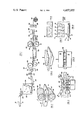
- FIG. 1 is a schematic, elevational view of a line of equipment for performing the improved method herein.
- FIG. 2 is a schematic, perspective fragmentary view of the compression-tacking apparatus
- FIG. 3 is a perspective, fragmentary view of the needling step.
- FIG. 4 is an enlarged, fragmentary cross-sectional view of the compression-tacking step
- FIG. 5 is an enlarged, fragmentary view of the needling step.
- FIG. 6 is a cross-sectional view of the non-woven padding.
- FIG. 7 is a top plan view, schematically illustrating the separate oriented layers which were used in the prior art blankets.
- FIG. 8 is an elevational view of the laminated or layered prior art blanket.
- FIG. 6 illustrates a section of the non-woven, needled, randomly oriented fiber padding 10 which is the desired product of the method of this invention.
- This padding may be formed of random lengths of mixtures of fibers from different cloths or rags which are randomly oriented and intertwined to form a relatively thick pad.
- the thickness of the pad and the weight per unit portion thereof may be varied substantially.
- a typical pad may be one-eighth of an inch in thickness up to an inch or more in thickness. Its weight per unit will vary depending upon the fibers utilized.
- These fibers may be obtained by tearing apart rags made of any of the available types of cloth or alternatively may be made of virgin fiber materials or cloths.
- the prior art padding 11 (see FIGS. 7 and 8), a number of separate layers, as for example layers 12, 13, 14 and 15, were laid one upon another by garnet machines. Each layer is formed of fibers oriented in generally the same direction, with one layer being oriented transversely relative to the next layer. These layers were laid, one upon another, with whatever desired number of layers were specified, upon a conveyor which carry the laminar blanket through a needling machine. As can be seen, the padding produced by the method of this invention is of a single layer, eliminating the prior art garnet uses.
- the process herein typically begins with a bale 18 of rags or other cloth.
- the bale is placed upon a bale conveyor 19 and then torn apart or shredded into constituent fibers in a conventional shredder which is schematically illustrated by the toothed rollers 20-21.
- the fibers from the shredder are poured into the top of a collection chamber 22 where they fall upon a floor conveyor belt 23 that carries the fibers to a wall belt 24 which is in a generally upright arrangement. As shown by the arrows in FIG. 1, the fibers are carried up the wall belt 24 which is formed of an endless belt engaging around opposing rollers with a suitable power means.
- the belt itself may have surface roughenings or attachments for carrying the fibers.
- the fibers reaching the top of the belt fall into the space between the belt and the adjacent wall of the collection chamber and float down to an outlet 25 at the bottom of the chamber.
- the fibers coming out of the outlet which may be spread by suitable spreading rollers (not shown) form a single, thick, layer 27 upon a conveyor belt 28.
- the layer which is formed of loosely piled fibers that are randomly oriented, is carried by the conveyor 28 and then through guide rolls 29 to a layer reconstituting apparatus 30. This apparatus functions to tear up and reconstitute the layer in order to get better, more even distribution of the fibers within the blanket.
- the layer reconstituting apparatus may include a slowly rotating roller 31 having rough, tooth-like surfaces for tearing and shredding the blanket.
- the blanket is guided and held against the roller 31 by means of a suitable guide plate 32.
- a large, faster rotating roller 33 which also has a rough, toothed surface. This surface may be formed of rough mesh or of separate machined teeth or the like.
- the fast rotating roller pulls and shreds the blanket further.
- the fiber from the now shredded blanket is drawn to a roller 35 which is provided with an internal vacuum by means of a suitable vacuum pump (not shown).
- This roller may have perforations on its surface in order to attract, by vacuum, the fibers which are guided along suitable rollers 36 to form a new, single layer blanket 37, like the original blanket 27, but now more evenly and carefully distributed.
- the new single layer 27 is carried by a belt conveyor 39 to the compression-tacking apparatus.
- the compression-tacking apparatus is formed of opposed rollers 40 and 41, each containing a tack needle group 42.
- the points 43 of the needles may be formed in a barbed configuration, as illustrated in FIG. 4.
- the needles are mounted upon a bar 44 which is carried by a mechanical mechanism that causes the needles to move outwardly of their respective rollers through perforations 45 in the roller walls.
- the needle bars 44 are each moved in an elliptical path as illustrated by the dotted lines in FIG. 2.
- the needles extend outwardly through the perforations in their respective roller walls and because of the elliptical movement of the needle bars, travel momentarily with the moving blanket and rollers and then retract.
- the bars successively move toward the blanket so that first one and then the other group of needles penetrate transversely of the blanket at the location of the compression or pinching.
- the blanket is next advanced upon a conveyor 47 to the needle press 48.
- the needle press is a conventional apparatus utilizing a densely arranged group of needles 49 mounted upon a vertically reciprocating platen 50. Upon downward movement, the needles transversely penetrate the blanket and depending upon the predetermined spacing, the platen may compress the blanket against a lower platen 51.
- the needling is rapid and repetitive so as to hit each section of the blanket numerous times for intertwining the fibers and causing them to interlock.
- These needles may likewise have barbed tips, if desired.
- the blanket after the needling is pulled by pull rollers 52 to a suitable conventional mechanism to wind the blanket into a roll 53.
- the roll may be sent to another place where it can be utilized to manufacture products or alternatively, instead of a roll, the blanket may be die cut into predetermined sizes or shapes to make finished products directly off the line.
- the number of needles per unit area and the number of times the needles penetrate the blanket incremental areas may be varied, depending upon the requirements or specifications, of the finished product.
- the resultant product typically contains a mixture of different fibers obtained from different rags or cloths, with the fibers randomly oriented and mechanically intertwined and interlocked to form a stable pad or mat which is difficult to tear or dimensionally disturb.
- this pad may be used for a variety of purposes as explained previously.
Abstract
Description
Claims (1)
Priority Applications (1)
| Application Number | Priority Date | Filing Date | Title |
|---|---|---|---|
| US06/412,573 US4457055A (en) | 1982-08-30 | 1982-08-30 | Method for forming needled, non-woven fiber padding |
Applications Claiming Priority (1)
| Application Number | Priority Date | Filing Date | Title |
|---|---|---|---|
| US06/412,573 US4457055A (en) | 1982-08-30 | 1982-08-30 | Method for forming needled, non-woven fiber padding |
Publications (1)
| Publication Number | Publication Date |
|---|---|
| US4457055A true US4457055A (en) | 1984-07-03 |
Family
ID=23633541
Family Applications (1)
| Application Number | Title | Priority Date | Filing Date |
|---|---|---|---|
| US06/412,573 Expired - Lifetime US4457055A (en) | 1982-08-30 | 1982-08-30 | Method for forming needled, non-woven fiber padding |
Country Status (1)
| Country | Link |
|---|---|
| US (1) | US4457055A (en) |
Cited By (11)
| Publication number | Priority date | Publication date | Assignee | Title |
|---|---|---|---|---|
| FR2618458A1 (en) * | 1987-07-23 | 1989-01-27 | Fehrer Textilmasch | DEVICE FOR NEEDING A SAIL OF CARD |
| US4926530A (en) * | 1987-12-11 | 1990-05-22 | Morrison Berkshire, Inc. | Method for manufacturing needled felts having machine direction oriented fibers |
| GB2234989A (en) * | 1989-07-25 | 1991-02-20 | Dunlop Ltd | Manufacture of carbon fibre preform |
| FR2670510A1 (en) * | 1990-12-12 | 1992-06-19 | Valeo | Method of producing a material based on reinforced elastomer, as well as a reinforced elastomer material obtained in particular by this method |
| US5196037A (en) * | 1990-07-02 | 1993-03-23 | Rossi Robert J | Products for use in polishing and the like and process for producing same |
| US5599603A (en) * | 1989-07-25 | 1997-02-04 | Dunlop Limited, A British Company | Manufacture of carbon fibre preform |
| US20030037419A1 (en) * | 2001-08-21 | 2003-02-27 | Karl-Josef Brockmanns | System for the needle-treatment of a conveyable fiber bat |
| US6564437B2 (en) * | 1998-10-30 | 2003-05-20 | Ppg Industries Ohio, Inc. | Double sided needled fiber glass mat for high flow thermoplastic composite |
| FR2862987A1 (en) * | 2003-11-28 | 2005-06-03 | Saint Gobain Vetrotex | GLASS MAT NEEDLED |
| JP2008240217A (en) * | 2007-03-29 | 2008-10-09 | Kuraray Co Ltd | Method for producing filament nonwoven fabric and method for producing substrate for artificial leather |
| CN102817184A (en) * | 2012-08-14 | 2012-12-12 | 苏州希尔克纤维制品有限公司 | Ring type needling compound machine |
Citations (6)
| Publication number | Priority date | Publication date | Assignee | Title |
|---|---|---|---|---|
| GB931611A (en) * | 1961-05-02 | 1963-07-17 | William Bywater Ltd | Improvements relating to web punching or needling machines |
| NL6605768A (en) * | 1966-04-29 | 1967-05-25 | ||
| AT275175B (en) * | 1966-09-28 | 1969-10-10 | Fehrer Maschf Dr Ernst | Device for needling fiber or hair fleece |
| DE2254484A1 (en) * | 1972-11-07 | 1974-05-09 | Ici Ltd | Polyamide matted fibre upholstering fabric - formed by needling fibres to both sides of scrim web with coarse and fine needles |
| US3950587A (en) * | 1971-01-12 | 1976-04-13 | Breveteam, S.A. | Non-woven textile fiber products having a relief-like structure |
| DE2630514A1 (en) * | 1976-07-07 | 1978-01-12 | Peter Dipl Ing Staerk | DEVICE FOR THE PRODUCTION OF VELVET, VELOR OR THE LIKE FROM A FIBER FIBER FIBER |
-
1982
- 1982-08-30 US US06/412,573 patent/US4457055A/en not_active Expired - Lifetime
Patent Citations (6)
| Publication number | Priority date | Publication date | Assignee | Title |
|---|---|---|---|---|
| GB931611A (en) * | 1961-05-02 | 1963-07-17 | William Bywater Ltd | Improvements relating to web punching or needling machines |
| NL6605768A (en) * | 1966-04-29 | 1967-05-25 | ||
| AT275175B (en) * | 1966-09-28 | 1969-10-10 | Fehrer Maschf Dr Ernst | Device for needling fiber or hair fleece |
| US3950587A (en) * | 1971-01-12 | 1976-04-13 | Breveteam, S.A. | Non-woven textile fiber products having a relief-like structure |
| DE2254484A1 (en) * | 1972-11-07 | 1974-05-09 | Ici Ltd | Polyamide matted fibre upholstering fabric - formed by needling fibres to both sides of scrim web with coarse and fine needles |
| DE2630514A1 (en) * | 1976-07-07 | 1978-01-12 | Peter Dipl Ing Staerk | DEVICE FOR THE PRODUCTION OF VELVET, VELOR OR THE LIKE FROM A FIBER FIBER FIBER |
Non-Patent Citations (2)
| Title |
|---|
| Burns, G. F., "Spooner Develops Equipment and Technology for Needled Velours Floor-coverings", Textile Month, (Feb. 1973), pp. 69-71. |
| Burns, G. F., Spooner Develops Equipment and Technology for Needled Velours Floor coverings , Textile Month, (Feb. 1973), pp. 69 71. * |
Cited By (19)
| Publication number | Priority date | Publication date | Assignee | Title |
|---|---|---|---|---|
| FR2618458A1 (en) * | 1987-07-23 | 1989-01-27 | Fehrer Textilmasch | DEVICE FOR NEEDING A SAIL OF CARD |
| US4926530A (en) * | 1987-12-11 | 1990-05-22 | Morrison Berkshire, Inc. | Method for manufacturing needled felts having machine direction oriented fibers |
| GB2234989A (en) * | 1989-07-25 | 1991-02-20 | Dunlop Ltd | Manufacture of carbon fibre preform |
| GB2234989B (en) * | 1989-07-25 | 1992-02-19 | Dunlop Ltd | Manufacture of carbon fibre preform |
| US5599603A (en) * | 1989-07-25 | 1997-02-04 | Dunlop Limited, A British Company | Manufacture of carbon fibre preform |
| US5196037A (en) * | 1990-07-02 | 1993-03-23 | Rossi Robert J | Products for use in polishing and the like and process for producing same |
| FR2670510A1 (en) * | 1990-12-12 | 1992-06-19 | Valeo | Method of producing a material based on reinforced elastomer, as well as a reinforced elastomer material obtained in particular by this method |
| US6564437B2 (en) * | 1998-10-30 | 2003-05-20 | Ppg Industries Ohio, Inc. | Double sided needled fiber glass mat for high flow thermoplastic composite |
| FR2828895A1 (en) * | 2001-08-21 | 2003-02-28 | Truetzschler & Co | DEVICE FOR NEEDING A VEHICLE FIBER VEHICLE |
| US20030037419A1 (en) * | 2001-08-21 | 2003-02-27 | Karl-Josef Brockmanns | System for the needle-treatment of a conveyable fiber bat |
| US6775887B2 (en) * | 2001-08-21 | 2004-08-17 | Trutzschler Gmbh & Co. Kg. | System for the needle-treatment of a conveyable fiber bat |
| CN100334283C (en) * | 2001-08-21 | 2007-08-29 | 特鲁菲舍尔股份有限公司及两合公司 | Needling device for deliverying fibre net |
| FR2862987A1 (en) * | 2003-11-28 | 2005-06-03 | Saint Gobain Vetrotex | GLASS MAT NEEDLED |
| WO2005054559A1 (en) * | 2003-11-28 | 2005-06-16 | Saint-Gobain Vetrotex France S.A. | Needled glass mat |
| EA007699B1 (en) * | 2003-11-28 | 2006-12-29 | Сэн-Гобэн Ветротекс Франс С. А. | Needled glass mat |
| US20070101561A1 (en) * | 2003-11-28 | 2007-05-10 | Saint-Gobain Vetrotex France S.A. | Needled glass mat |
| US7509714B2 (en) | 2003-11-28 | 2009-03-31 | Ocv Intellectual Capital, Llc | Needled glass mat |
| JP2008240217A (en) * | 2007-03-29 | 2008-10-09 | Kuraray Co Ltd | Method for producing filament nonwoven fabric and method for producing substrate for artificial leather |
| CN102817184A (en) * | 2012-08-14 | 2012-12-12 | 苏州希尔克纤维制品有限公司 | Ring type needling compound machine |
Similar Documents
| Publication | Publication Date | Title |
|---|---|---|
| US3950587A (en) | Non-woven textile fiber products having a relief-like structure | |
| US4416936A (en) | Nonwoven fabric and method for its production | |
| US4457055A (en) | Method for forming needled, non-woven fiber padding | |
| EP0350627B1 (en) | Apparatus for making voluminous fibre layers | |
| US4377889A (en) | Apparatus for controlling edge uniformity in nonwoven fabrics | |
| US3856602A (en) | Method of producing non-woven textile fiber products having a relief-like structure | |
| US4295251A (en) | Method for controlling edge uniformity in nonwoven fabrics | |
| EP2630287B1 (en) | Method and apparatus for producing a composite nonwoven | |
| US3428506A (en) | Method of producing a needled,nonwoven fibrous structure | |
| CN111394886A (en) | Non-woven fabric processing technology and processing equipment thereof | |
| DE3248753A1 (en) | METHOD FOR COMPRESSING FIBER FABRICS | |
| EP0598085B1 (en) | Tufted carpet and process for manufacturing the same | |
| US3257259A (en) | Method of making non-woven fabrics | |
| US3839114A (en) | Method and apparatus for making pile fabric | |
| CN113561619A (en) | Cow leather fiber composite base material production line and base material production process thereof | |
| EP1644565B1 (en) | Method for reinforcing a web of nonwoven fabric by means of needling | |
| US2794238A (en) | Fiber glass mat | |
| US3090099A (en) | Method of needle punching fabrics so as to interlace the fibers thereof | |
| EP0086996B1 (en) | Method of producing fibre-reinforced flat bodies | |
| HUT74138A (en) | A method and a plant for producing a mineral fiber-insulated web, and a mineral fiber-insulated plate | |
| DE1635590A1 (en) | Process for the production of fibrous sheet materials | |
| US2794237A (en) | Method of producing fiber glass mats | |
| EP0411248B1 (en) | Method for producing patterned textile needled felt or needled fleece sheets | |
| CN106240095A (en) | The method that the continuous protrusion replaced of formation and groove manufacture the polyester staple fiber layered product with elasticity and sound absorption properties from the teeth outwards | |
| US3112549A (en) | Needle punch machine |
Legal Events
| Date | Code | Title | Description |
|---|---|---|---|
| AS | Assignment |
Owner name: NORTHERN FIBRE PRODUCTS COMPANY, 50 WEST THIRD ST. Free format text: ASSIGNMENT OF ASSIGNORS INTEREST.;ASSIGNORS:AMBROSE, JERE B.;VAN COMPERNOLLE, DONALD D.;DAVIS, ALFRED L.;REEL/FRAME:004041/0633;SIGNING DATES FROM 19820715 TO 19820721 |
|
| STCF | Information on status: patent grant |
Free format text: PATENTED CASE |
|
| AS | Assignment |
Owner name: CITIBANK, N.A., AS AGENT FOR THE BANKS, 641 LEXING Free format text: SECURITY INTEREST;ASSIGNOR:NORTHERN FIBRE PRODUCTS COMPANY A MI. CORP.;REEL/FRAME:004580/0604 Effective date: 19860611 Owner name: CITIBANK, N.A., AS AGENT FOR THE BANKS,NEW YORK Free format text: SECURITY INTEREST;ASSIGNOR:NORTHERN FIBRE PRODUCTS COMPANY A MI. CORP.;REEL/FRAME:004580/0604 Effective date: 19860611 |
|
| AS | Assignment |
Owner name: SHELLER-GLOBE CORPORATION, A CORP. OF OH. Free format text: ASSIGNMENT OF ASSIGNORS INTEREST.;ASSIGNOR:NORTHERN FIBRE PRODUCTS COMPANY;REEL/FRAME:004699/0811 Effective date: 19870424 Owner name: SHELLER-GLOBE CORPORATION, A CORP. OF OH.,OHIO Free format text: ASSIGNMENT OF ASSIGNORS INTEREST;ASSIGNOR:NORTHERN FIBRE PRODUCTS COMPANY;REEL/FRAME:004699/0811 Effective date: 19870424 |
|
| FEPP | Fee payment procedure |
Free format text: PAT HLDR NO LONGER CLAIMS SMALL ENT STAT AS INDIV INVENTOR (ORIGINAL EVENT CODE: LSM1); ENTITY STATUS OF PATENT OWNER: LARGE ENTITY |
|
| FPAY | Fee payment |
Year of fee payment: 4 |
|
| AS | Assignment |
Owner name: SHELLER-GLOBE CORPORATION, A CORP. OF DE Free format text: RELEASED BY SECURED PARTY;ASSIGNOR:CITIBANK, NA AS AGENT;REEL/FRAME:005110/0871 Effective date: 19881209 |
|
| FPAY | Fee payment |
Year of fee payment: 8 |
|
| FPAY | Fee payment |
Year of fee payment: 12 |