US4417723A - Tuyere for blowing gases into molten metal bath container - Google Patents
Tuyere for blowing gases into molten metal bath container Download PDFInfo
- Publication number
- US4417723A US4417723A US06/336,685 US33668582A US4417723A US 4417723 A US4417723 A US 4417723A US 33668582 A US33668582 A US 33668582A US 4417723 A US4417723 A US 4417723A
- Authority
- US
- United States
- Prior art keywords
- tuyere
- blowing
- core body
- tube
- flow rate
- Prior art date
- Legal status (The legal status is an assumption and is not a legal conclusion. Google has not performed a legal analysis and makes no representation as to the accuracy of the status listed.)
- Expired - Lifetime
Links
Images


Classifications
-
- C—CHEMISTRY; METALLURGY
- C21—METALLURGY OF IRON
- C21C—PROCESSING OF PIG-IRON, e.g. REFINING, MANUFACTURE OF WROUGHT-IRON OR STEEL; TREATMENT IN MOLTEN STATE OF FERROUS ALLOYS
- C21C5/00—Manufacture of carbon-steel, e.g. plain mild steel, medium carbon steel or cast steel or stainless steel
- C21C5/005—Manufacture of stainless steel
-
- C—CHEMISTRY; METALLURGY
- C21—METALLURGY OF IRON
- C21C—PROCESSING OF PIG-IRON, e.g. REFINING, MANUFACTURE OF WROUGHT-IRON OR STEEL; TREATMENT IN MOLTEN STATE OF FERROUS ALLOYS
- C21C5/00—Manufacture of carbon-steel, e.g. plain mild steel, medium carbon steel or cast steel or stainless steel
- C21C5/28—Manufacture of steel in the converter
- C21C5/30—Regulating or controlling the blowing
- C21C5/35—Blowing from above and through the bath
-
- C—CHEMISTRY; METALLURGY
- C21—METALLURGY OF IRON
- C21C—PROCESSING OF PIG-IRON, e.g. REFINING, MANUFACTURE OF WROUGHT-IRON OR STEEL; TREATMENT IN MOLTEN STATE OF FERROUS ALLOYS
- C21C5/00—Manufacture of carbon-steel, e.g. plain mild steel, medium carbon steel or cast steel or stainless steel
- C21C5/28—Manufacture of steel in the converter
- C21C5/42—Constructional features of converters
- C21C5/46—Details or accessories
- C21C5/48—Bottoms or tuyéres of converters
-
- C—CHEMISTRY; METALLURGY
- C21—METALLURGY OF IRON
- C21C—PROCESSING OF PIG-IRON, e.g. REFINING, MANUFACTURE OF WROUGHT-IRON OR STEEL; TREATMENT IN MOLTEN STATE OF FERROUS ALLOYS
- C21C7/00—Treating molten ferrous alloys, e.g. steel, not covered by groups C21C1/00 - C21C5/00
- C21C7/04—Removing impurities by adding a treating agent
- C21C7/072—Treatment with gases
-
- C—CHEMISTRY; METALLURGY
- C22—METALLURGY; FERROUS OR NON-FERROUS ALLOYS; TREATMENT OF ALLOYS OR NON-FERROUS METALS
- C22B—PRODUCTION AND REFINING OF METALS; PRETREATMENT OF RAW MATERIALS
- C22B9/00—General processes of refining or remelting of metals; Apparatus for electroslag or arc remelting of metals
Definitions
- This invention relates to a gas blowing tuyere to be used in bottom or side walls of various metal refining furnaces or molten metal containers such as ladles and the like.
- molten metal containers for holding molten metal for refining, lagging, storing, transporting or for other purposes.
- LD converters there are known a diversity of converters, including LF furnace, VAD furnace, AOD furnace, ASEA-SKF furnace and RH and DH vacuum melters.
- molten metal containers other than those refining furnaces are ladles, metal mixers, mixer cars and the like. Most of such molten metal containers more or less require stirring the content constantly or intermittently.
- the converters which are designed to blow pure oxygen into molten metal are generally classified as a top blowing type and a bottom blowing type, of which the top blowing type has been more popular in the art although both have long histories of use.
- the bottom blowing type converter are increasingly accepted these days to utilize the stirring effect peculiar to the climbing streams of the bottom blown gas. Namely, it has been revealed that metallurgical reactions are improved to a significant degree as a result of the positive stirring actions of the climbing gas streams on the molten steel and slag, as compared with a pure oxygen top blowing type converter. Therefore, there is even a trend of entirely replacing the top blowing type converters by the bottom blowing type.
- the present inventors have conducted a study of the top and bottom blowing converters in an attempt to develop a new refining process which incorporates top and bottom blown gases parallelly in such a manner as to secure the advantages of the bottom blowing while retaining the merits of the top blowing, for instance, versatility in refining.
- composition and temperature of the molten bath were maintained uniform in the entire areas of the furnace, improving the success rate of attaining a target composition at turn down.
- the molten steel 5 in the vicinity of the bottom wall 2 is partly solidified by the primary cooling action of the blown-in gas, forming a mushroom (a mass of base metal) as indicated by 3.
- the blown-in gas is injected into the molten steel 5 through narrow gas passages 4 which are formed in the mushroom 3, and climbs up through the molten steel 5 in the form of bubbles 6.
- the gas passages 4 are not sufficiently formed due to an increased resistance of the mushroom 3 and the blowing is blocked with relatively high frequency, failing to blow in the gas in a stable condition.
- the back pressure of the tuyere has to be raised to a level higher than 10 kg/cm 2 G in the case of a mono-tube tuyere, although it depends on the static pressure of the molten steel.
- the flow rate of the blowing gas is to be maintained at a value lower than 0.1 Nm 3 /min versus one ton of molten steel as mentioned hereinbefore, it becomes necessary to make the tuyere hole diameter smaller.
- the double-tube tuyere has been effective particularly for simultaneously blowing in a gas and powder or the like, in addition to injection of a large quantity of oxygen or the like.
- the concentric double-tube tuyere has a problem in that the gas flows from the inner tube have a large influence and in some case the blowing operation is thereby rendered unstable. Therefore, it is unsuitable particularly for blowing in a gas at a relatively small flow rate or for controlling the gas flow rate over a wide range, as manifested, for example, by the results of experiments shown in FIGS. 3 and 4.
- the graphs of FIGS. 3 and 4 show variations in the gas flow rates of a concentric double-tube tuyere which is anchored in a bottom wall of a converter to blow in oxygen through the inner tube and a cooling CnHm gas through the outer tube, detecting the blowing gas pressure in pipings in the vicinity of the tuyere.
- the blowing becomes unstable with extremely large variations in the inner and outer tube pressures Ip and Op in the case of FIG. 4 where the flow rate of oxygen through the inner tube is about 1/2.5. It will be understood therefrom that the use of a concentric double-tube tuyere does not give sufficient solutions to the above-mentioned problems.
- the convention tuyeres have a detrimental drawback in that the refractory wall around the tuyere is worn out considerably by the actions of the gas jets which are injected into the molten steel, particularly by the bottom beating actions (back attacks) of the downward streams which are formed immediately after injection.
- the conventional tuyeres are defective in construction for blowing in an inert gas or oxygen, and a tuyere of the afore-mentioned novel construction has been provided as a result of extensive studies and experiments.
- a more particular object of the present invention is to provide an improved blowing tuyere which is capable of uniform and stable gas blowing operations continuously and which is adapted to suppress to a minimum the erosion of surrounding refractory walls by back attacks of injected gases which would otherwise shorten the service life of the converter.
- FIG. 1 is a sectional view of a conventional tuyere
- FIG. 2 is a perspective view of a conventional concentric double-tube tuyere
- FIG. 3 is a graph plotting variations in internal pressures of tuyere tubes in a high flow rate blowing operation by the concentric double-tube tuyere;
- FIG. 4 is a graph plotting variations in internal pressures of tuyere tubes in a low flow rate blowing operation by the conventional concentric double-tube tuyere;
- FIG. 5 is a sectional view of a single-annular blowing tuyere according to the present invention.
- FIG. 6 is a perspective view of another embodiment of the present invention, which is in the form of a double-annular blowing tuyere;
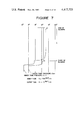
- FIG. 7 is a graph plotting variations in internal pressures in a high flow rate blowing operation by the double-annulus or dual type annular tuyere of the invention.
- FIG. 8 is a graph plotting variations in internal pressures in a low flow rate blowing operation by the dual type annular tuyere of the invention.
- FIG. 9 is a graph plotting occurrences and nonoccurrences tuyere blockade in relation to the gap width and tuyere back pressure
- FIG. 10 is a graph showing the heightwise erosion of a single type annular tuyere in relation to the number of refining charges
- FIG. 11 is a graph showing the heightwise erosion of a dual type annular tuyere in relation to the number of refining charges
- FIG. 12 is a chart of a refining time schedule in one example
- FIG. 13 is a graph showing the relation between the pressure range and the flow rate range of the single type annular tuyere of the invention.
- FIGS. 14 and 15 are graphs showing relations of the gap width t between a core body and an outer tube, the diameter d of the core body, the outside diameter D of the outer tube, and the blowing conditions.
- the tuyere includes a cylindrical core body 19 with a refractory material 9 filled in an inner tube 7, and an outer tube 8 which is disposed concentrically on the outer side of the inner tube 7 with an apppropriate gap or space formed therebetween.
- the outer tube 8 has a lower bulged portion 8' with a blowing gas inlet 10 at the lower end thereof an a flange 11 which projects integrally from the outer tube body at a position slightly above the bulged portion 8' to thereby secure the tuyere to a shell 12.
- an inert gas which enters the outer tube 8 in the direction of arrow A through the gas inlet 10 climbs up the bulged portion 8' as indicated by arrow B and leaves the tuyere through an annular spout 13 formed between the inner and outer tubes 7 and 8.
- a mushroom 3 is likewise formed over the tuyere so that the inert gas is released into molten steel 5 through gas passages 4 and rises in the form of small bubbles 6.
- FIG. 6 which illustrates another embodiment of the present invention in a perspective view
- an outermost or second outer tube 18 is disposed concentrically around the first outer tube 8 with a small gap or space formed therebetween.
- a dual annular tuyere which will be hereinafter referred to as a dual type annular tuyere.
- the dual type annular tuyere is shown as having a central core body with a refractory material filled in an inner tube, but there may be employed a tuyere construction which instead has a round solid rod of a refractory material or ceramic or other filler material at the center thereof.
- FIGS. 7 and 8 show the results of experiments on the dual type annular tuyere (FIG. 6) in a manner similar to FIGS. 3 and 4. More specifically, as shown in FIGS. 7 and 8, the blow-in gas pressure remains stable even when the flow rate of oxygen gas is reduced to about 1/2.5 in contrast to the performance of the conventional concentric double-tube tuyere (FIG. 2). The stability of the inner pressure Ip in the low flow rate blowing by the dual type annular tuyere (FIG.
- the range of such flow rate control varies depending upon the tuyere design.
- stable blowing operation is possible in the range of 0.02-0.057 Nm 3 /min.ton in a case employing a pair of single type annular tuyeres each having an inner core tube of 15.5 mm in outside diameter and a gap width of 1.8 mm between the inner and outer tubes, and controlling the blowing gas pressure as represented by the tuyere back pressure in the range of about 5.5-18.0 kg/cm 2 .
- the blowing tuyere according to the present invention permits easy control of the flow rate in a broad range of 3 to 5 as a ratio of the maximum to minimum flow rate, an amazing attainment as compared with the conventional tuyeres in which the ratio is 1.5 to 2.0 at most.
- the stirring force of the blow-in gas is doubled. It follows that the stirring force can be controlled to a quintuplicate level by the use of a tuyere which is capable to controlling the flow rate to a value 2.5 times as great as the minimum flow rate as mentioned hereinbefore. This implies that the dual type annular tuyere has extremely favorable characteristics for the top and bottom blown converters.
- the graph of FIG. 9 shows the results of experiments studying the liability to tuyere blocking by varying the gap width and back pressure of tuyeres in a refining process using a 240-ton converter with a pair of single type annular tuyeres of FIG. 5 embedded at the bottom thereof.
- a solid black circle indicates the occurrence of tuyrere blockade while a white or blank circle denotes nonoccurrence.
- the blank circle also indicates that a stable blowing operation was possible without the trouble of tuyere blockade over several hundreds of charges.
- Straight lines B and C are guide lines which indicate the boundaries of the regions of the blank and solid black circles. In other words, the safe region is on the higher back pressure side or narrower gap side of these lines.
- the straight line A corresponds to the static pressure of molten steel so that in some cases the back pressure of the tuyere can be lowered to a level close to that line. In such a case, however, the back pressure should be increased as promptly as possible in order to secure a desired gas flow rate.
- curve D indicates the condition where the calculated value of linear gas velocity at the spout end of the tuyere reaches the sonic level in a blowing operation using an Ar gas blowing tuyere over a length of about 1200 mm
- curve E denotes a level which is 2 kg/cm 2 lower than the curve D.
- the number of charges and heightwise erosion of the tuyere in blowing operations at a pressure higher than curve D or at least higher than curve E were as shown in FIG. 10.
- the amount of erosion of the double-tube tuyere which is about 1.05 mm/CH, can be diminished to about 1/2, namely, to about 0.46 mm/CH by the use of the tuyere shown in FIG. 5.
- the amount of erosion of the refractory material in blowing operations by the concentric double-tube tuyere and the dual type annular tuyere are shown in FIG. 11 for the purpose of comparison.
- FIG. 12 is a chart showing a refining time schedule for each charge in an inert gas blowing experiment using a single type annular tuyere.
- N 2 gas was blown into the converter before charging molten pig iron, and the blowing gas was switched to Ar as soon as the charging is finished to start refining, in order to prevent N 2 from dissolving into the molten steel during the refining process.
- the blowing gas was switched again to N 2 at a time point when the refining was terminated.
- FIG. 13 graphically illustrates an example of flow rate control using the single type annular tuyere. As shown, it is possible to stably control the flow rate of the blowing gas at 3.0-8.0 Nm 3 /min by controlling the blowing gas pressure in a broad range of about 5.2-15.4 kg/cm 2 G.
- the annular tuyere according to the present invention is effective for broadening the flow rate control range and prolonging the life of the refractory walls in the vicinity of the tuyere.
- a further study including pilot tests on annular tuyeres of various dimensions revealed that the back attacks due to the back flows of the blown gas could be increased in some cases depending upon the tuyere design, giving rise to a necessity for establishing a dimensional definition of a preferred tuyere design.
- annular tuyere according to the present invention is preferred to be constructed to satisfy the following conditions.
- t is the width of the gap between the core body and outer tube of the tuyere
- d is the diameter of the core body
- D is the outside diameter of the outer tube
- the coefficient of flow rate through a tuyere (in other words, the coefficient of the stirring flow) varies depending upon the opening angle of the tuyere hole, which for example is about 0.75 in the case of a straight tuyere as shown in FIG. 5. It is therefore considered that the lower limit of the stable blowing velocity of the above-mentioned tuyere is about 75% of the sonic velocity.
- FIG. 14 shows the relationship between the dimensional factors of the tuyere and the melting loss of the refractory material.
- the chain line is a subsonic line (75% of sonic velocity) in an operation blowing a gas through one tuyere hole at a rate of 0.08 Nm 3 /min per ton of molten steel, while the solid line is a subsonic line (do.) in an operation blowing a gas through one tuyere hole at a rate of 0.06 Nm/ 3 /min per ton of molten steel.
- the extents of erosion of the refractory material around the tuyere is indicated by a blank circle (for a loss lower than 0.4 mm/charge), a half-black circle (for a loss of 0.4-0.6 mm/charge) and a solid black circle (for a loss greater than 0.6 mm/charge). It is known from the data of FIG. 14 that, in order to secure blowing in the subsonic range, the tuyere should have a smaller ratio of t/D when the ratio d/D is on the higher side or vice versa.
- FIG. 15 shows the range of smaller erosion, which is determined on the basis of the data given in FIG. 14.
- the ratio of d/D is limited to 0.4 since otherwise a vacuum is developed in the gas flows at the spout end of the tuyere and the molten steel tends to flow into the tuyere under the influence of even a slight outer disturbance, coupled with increases in the amount of erosion and the trend toward the back attack phenomenon.
- d/D ratios smaller than 0.1 are also excluded as they make no substantial difference from the known single tube tuyere of FIG. 1 although the adverse effect of the vacuum portions is reduced.
- the tuyere loses the characteristics inherent to the annular tuyere of the invention if the ratio t/D becomes greater than 0.08, showing a performance similar to the double-tube type tuyere. Further, a t/D ratio smaller than 0.02 reflects an extremely small gap width of the tuyere which is unacceptable in consideration of difficulties in the machining stage. Accordingly, t/D ratios greater than 0.08 as well as t/D ratios smaller than 0.02 are excluded from the range of the present invention. As mentioned hereinbefore, it is desirable to determine the values of t/D and d/D in an inversely proportional relation and to exclude the range of t/D>-0.11 d/D+0.11 where the amount of erosion increases.
- the hatched area of FIG. 15 defines the preferred range of the present invention which permits control of the blowing gas flow rate over a broad range and at the same time suppressing the melting loss of the refractory material in the vicinity of the blowing tuyere to a minimum.
- the present invention makes it possible to carry out a uniform and safe gas blowing operation continuously when gas stirring is required for molten metals in various containers by providing an annular blowing tuyere or tuyeres in the bottom or side walls of the containers.
- the tuyere of the invention can reduce the attritional erosion by back attacks of the refractory material to a considerable degree, so that, if applied to converters, it contributes greatly to the elimination of obstacles which lie in the way to the industrialization of top and bottom blown refining processes.
Landscapes
- Chemical & Material Sciences (AREA)
- Engineering & Computer Science (AREA)
- Materials Engineering (AREA)
- Metallurgy (AREA)
- Organic Chemistry (AREA)
- Manufacturing & Machinery (AREA)
- Mechanical Engineering (AREA)
- Carbon Steel Or Casting Steel Manufacturing (AREA)
- Treatment Of Steel In Its Molten State (AREA)
Abstract
Description
2C+O.sub.2 =2CO
0.02≦t/D≦0.08
0.1≦d/D≦0.4
t/D≦-0.11d/D+0.11
Claims (8)
t/D=-0.11d/D+0.11
Applications Claiming Priority (2)
| Application Number | Priority Date | Filing Date | Title |
|---|---|---|---|
| JP56169465A JPS5871343A (en) | 1981-10-22 | 1981-10-22 | Nozzle for blowing of gas provided in molten metal vessel |
| JP56-169465 | 1981-10-22 |
Publications (1)
| Publication Number | Publication Date |
|---|---|
| US4417723A true US4417723A (en) | 1983-11-29 |
Family
ID=15887064
Family Applications (1)
| Application Number | Title | Priority Date | Filing Date |
|---|---|---|---|
| US06/336,685 Expired - Lifetime US4417723A (en) | 1981-10-22 | 1982-01-04 | Tuyere for blowing gases into molten metal bath container |
Country Status (3)
| Country | Link |
|---|---|
| US (1) | US4417723A (en) |
| JP (1) | JPS5871343A (en) |
| CA (1) | CA1168862A (en) |
Cited By (11)
| Publication number | Priority date | Publication date | Assignee | Title |
|---|---|---|---|---|
| US4741515A (en) * | 1986-10-20 | 1988-05-03 | Bethlehem Steel Corporation | Apparatus for introducing gas into a metallurgical vessel |
| US4754951A (en) * | 1987-08-14 | 1988-07-05 | Union Carbide Corporation | Tuyere assembly and positioning method |
| US4795138A (en) * | 1987-11-18 | 1989-01-03 | L-Tec Company | Metallurgical tuyere and method of calibrating same |
| US4808222A (en) * | 1987-09-30 | 1989-02-28 | Ashland Oil, Inc. | Powdered flux for treating aluminum-silicon alloys |
| US5329545A (en) * | 1991-12-07 | 1994-07-12 | Air Products And Chemicals, Inc. | Tuyere for installation in hearth of electric arc furnace |
| WO1996036580A1 (en) * | 1995-05-16 | 1996-11-21 | Monofrax Inc. | Process for making fused-cast refractory products |
| US20030212505A1 (en) * | 2002-05-13 | 2003-11-13 | Rojas Luis Paredes | System for a non-invasive online continuous measurement of phase levels in converters or pyrometallurgical furnaces |
| US20070096373A1 (en) * | 2003-06-16 | 2007-05-03 | Khloponin Viktor N | Tuyere device for introducing gaseous media under a liquid-metal layer |
| WO2009028909A3 (en) * | 2007-08-29 | 2009-05-07 | Posco | Tuyere for manufacturing molten iron and method for injecting gas using the same |
| CN103805733A (en) * | 2002-11-16 | 2014-05-21 | Sms西马格股份公司 | Gas supply system for a metallurgical furnace and operating method for said system |
| EP3766598A1 (en) | 2019-07-17 | 2021-01-20 | Air Products And Chemicals, Inc. | Tuyere for a basic oxygen furnace |
Families Citing this family (2)
| Publication number | Priority date | Publication date | Assignee | Title |
|---|---|---|---|---|
| JP4765372B2 (en) * | 2005-03-31 | 2011-09-07 | Jfeスチール株式会社 | Gas blown tuyere |
| JP2011026709A (en) * | 2010-09-28 | 2011-02-10 | Jfe Steel Corp | Gas-blowing tuyere |
Citations (16)
| Publication number | Priority date | Publication date | Assignee | Title |
|---|---|---|---|---|
| US3330645A (en) * | 1962-08-07 | 1967-07-11 | Air Liquide | Method and article for the injection of fluids into hot molten metal |
| US3343829A (en) * | 1964-03-14 | 1967-09-26 | British Cast Iron Res Ass | Porous plug assembly for metallurgical receptacle |
| US3397878A (en) * | 1965-11-19 | 1968-08-20 | Union Carbide Corp | Under-bath tuyere |
| US3490775A (en) * | 1967-12-15 | 1970-01-20 | Langford W Henshaw | Stuffing box packing assembly |
| US3615086A (en) * | 1969-06-20 | 1971-10-26 | David A Jepson | Apparatus for stirring molten metal |
| US3703279A (en) * | 1969-08-15 | 1972-11-21 | Joslyn Mfg & Supply Co | Reactor |
| US3724830A (en) * | 1969-08-15 | 1973-04-03 | Joslyn Mfg & Supply Co | Molten metal reactor vessel |
| US3744781A (en) * | 1971-06-24 | 1973-07-10 | Beatrice Foods Co | Method and apparatus for gas stirring of molten metal |
| US3844768A (en) * | 1971-05-28 | 1974-10-29 | Creusot Loire | Process for refining alloy steels containing chromium and including stainless steels |
| US3971548A (en) * | 1974-03-20 | 1976-07-27 | Allmanna Svenska Elektriska Aktiebolaget | Metallurgical furnace having a blast injection nozzle |
| US4022447A (en) * | 1976-02-23 | 1977-05-10 | United States Steel Corporation | Supersonic nozzle for submerged tuyere oxygen steelmaking process |
| US4249719A (en) * | 1974-08-08 | 1981-02-10 | Eisenwerk-Gesellschaft Maximilianshutte Mbh | Tuyere for the injection of reaction gas |
| US4266970A (en) * | 1978-12-21 | 1981-05-12 | Kawasaki Steel Corporation | Method for blowing gas from below into molten steel in refining vessel |
| US4268017A (en) * | 1979-12-28 | 1981-05-19 | Exxon Research & Engineering Co. | Reactor with extractable feed nozzle |
| US4293123A (en) * | 1978-12-22 | 1981-10-06 | Klockner-Humboldt-Deutz Ag | Blow lance |
| US4311518A (en) * | 1979-10-31 | 1982-01-19 | Canadian Liquid Air Ltd./Air Liquide Canada Ltee | Homogenization of metal using gas |
-
1981
- 1981-10-22 JP JP56169465A patent/JPS5871343A/en active Pending
- 1981-12-22 CA CA000393020A patent/CA1168862A/en not_active Expired
-
1982
- 1982-01-04 US US06/336,685 patent/US4417723A/en not_active Expired - Lifetime
Patent Citations (16)
| Publication number | Priority date | Publication date | Assignee | Title |
|---|---|---|---|---|
| US3330645A (en) * | 1962-08-07 | 1967-07-11 | Air Liquide | Method and article for the injection of fluids into hot molten metal |
| US3343829A (en) * | 1964-03-14 | 1967-09-26 | British Cast Iron Res Ass | Porous plug assembly for metallurgical receptacle |
| US3397878A (en) * | 1965-11-19 | 1968-08-20 | Union Carbide Corp | Under-bath tuyere |
| US3490775A (en) * | 1967-12-15 | 1970-01-20 | Langford W Henshaw | Stuffing box packing assembly |
| US3615086A (en) * | 1969-06-20 | 1971-10-26 | David A Jepson | Apparatus for stirring molten metal |
| US3703279A (en) * | 1969-08-15 | 1972-11-21 | Joslyn Mfg & Supply Co | Reactor |
| US3724830A (en) * | 1969-08-15 | 1973-04-03 | Joslyn Mfg & Supply Co | Molten metal reactor vessel |
| US3844768A (en) * | 1971-05-28 | 1974-10-29 | Creusot Loire | Process for refining alloy steels containing chromium and including stainless steels |
| US3744781A (en) * | 1971-06-24 | 1973-07-10 | Beatrice Foods Co | Method and apparatus for gas stirring of molten metal |
| US3971548A (en) * | 1974-03-20 | 1976-07-27 | Allmanna Svenska Elektriska Aktiebolaget | Metallurgical furnace having a blast injection nozzle |
| US4249719A (en) * | 1974-08-08 | 1981-02-10 | Eisenwerk-Gesellschaft Maximilianshutte Mbh | Tuyere for the injection of reaction gas |
| US4022447A (en) * | 1976-02-23 | 1977-05-10 | United States Steel Corporation | Supersonic nozzle for submerged tuyere oxygen steelmaking process |
| US4266970A (en) * | 1978-12-21 | 1981-05-12 | Kawasaki Steel Corporation | Method for blowing gas from below into molten steel in refining vessel |
| US4293123A (en) * | 1978-12-22 | 1981-10-06 | Klockner-Humboldt-Deutz Ag | Blow lance |
| US4311518A (en) * | 1979-10-31 | 1982-01-19 | Canadian Liquid Air Ltd./Air Liquide Canada Ltee | Homogenization of metal using gas |
| US4268017A (en) * | 1979-12-28 | 1981-05-19 | Exxon Research & Engineering Co. | Reactor with extractable feed nozzle |
Cited By (18)
| Publication number | Priority date | Publication date | Assignee | Title |
|---|---|---|---|---|
| US4741515A (en) * | 1986-10-20 | 1988-05-03 | Bethlehem Steel Corporation | Apparatus for introducing gas into a metallurgical vessel |
| US4754951A (en) * | 1987-08-14 | 1988-07-05 | Union Carbide Corporation | Tuyere assembly and positioning method |
| US4808222A (en) * | 1987-09-30 | 1989-02-28 | Ashland Oil, Inc. | Powdered flux for treating aluminum-silicon alloys |
| US4795138A (en) * | 1987-11-18 | 1989-01-03 | L-Tec Company | Metallurgical tuyere and method of calibrating same |
| US5329545A (en) * | 1991-12-07 | 1994-07-12 | Air Products And Chemicals, Inc. | Tuyere for installation in hearth of electric arc furnace |
| WO1996036580A1 (en) * | 1995-05-16 | 1996-11-21 | Monofrax Inc. | Process for making fused-cast refractory products |
| US5738811A (en) * | 1995-05-16 | 1998-04-14 | Monofrax Inc. | Process for making fused-cast refractory products |
| CN1092621C (en) * | 1995-05-16 | 2002-10-16 | 莫诺弗拉克斯公司 | Process for making fused-cast refractory products |
| US20030212505A1 (en) * | 2002-05-13 | 2003-11-13 | Rojas Luis Paredes | System for a non-invasive online continuous measurement of phase levels in converters or pyrometallurgical furnaces |
| CN103805733A (en) * | 2002-11-16 | 2014-05-21 | Sms西马格股份公司 | Gas supply system for a metallurgical furnace and operating method for said system |
| US20070096373A1 (en) * | 2003-06-16 | 2007-05-03 | Khloponin Viktor N | Tuyere device for introducing gaseous media under a liquid-metal layer |
| US7534390B2 (en) * | 2003-06-16 | 2009-05-19 | Techcom Import Export Gmbh | Tuyere device for introducing gaseous media under a liquid-metal layer |
| WO2009028909A3 (en) * | 2007-08-29 | 2009-05-07 | Posco | Tuyere for manufacturing molten iron and method for injecting gas using the same |
| US20110101576A1 (en) * | 2007-08-29 | 2011-05-05 | Posco | Tuyere for Manufacturing Molten Iron and Method for Injecting Gas Using the Same |
| AU2008293166B2 (en) * | 2007-08-29 | 2011-09-08 | Posco | Tuyere for manufacturing molten iron and method for injecting gas using the same |
| RU2478121C2 (en) * | 2007-08-29 | 2013-03-27 | Поско | Cast iron tuyere and method of tuyere gas injection |
| EP3766598A1 (en) | 2019-07-17 | 2021-01-20 | Air Products And Chemicals, Inc. | Tuyere for a basic oxygen furnace |
| US11155890B2 (en) | 2019-07-17 | 2021-10-26 | Air Products And Chemicals, Inc. | Tuyere for a basic oxygen furnace |
Also Published As
| Publication number | Publication date |
|---|---|
| JPS5871343A (en) | 1983-04-28 |
| CA1168862A (en) | 1984-06-12 |
Similar Documents
| Publication | Publication Date | Title |
|---|---|---|
| US4417723A (en) | Tuyere for blowing gases into molten metal bath container | |
| US4426224A (en) | Lance for powder top-blow refining and process for decarburizing and refining steel by using the lance | |
| US6793710B2 (en) | Method for blowing oxygen in converter and top-blown lance for blowing oxygen | |
| EP0059289B1 (en) | Tuyère | |
| CA2203410C (en) | Process for vacuum refining molten steel and apparatus therefor | |
| US5911946A (en) | Snorkel for a degassing vessel | |
| JP4980175B2 (en) | Lance for molten iron refining and molten iron refining method | |
| JPS63121611A (en) | Method and device for stirring molten metal bath for electric arc furnace | |
| JP2582316B2 (en) | Melting method of low carbon steel using vacuum refining furnace | |
| US4394165A (en) | Method of preliminary desiliconization of molten iron by injecting gaseous oxygen | |
| US6346212B1 (en) | Converter | |
| US4398949A (en) | Method for stably refining high carbon steel | |
| JPS58167707A (en) | Method of smelting high-carbon steel by top and bottom-blown converter | |
| US4157813A (en) | Process for protecting a metallurgical tuyere against wear while minimizing the amount of liquid cooling agent supplied thereto | |
| JP3309301B2 (en) | Converter refining method and refining lance | |
| JP2877026B2 (en) | How to protect the refining tuyere | |
| JP4244546B2 (en) | Top blowing lance for converter smelting | |
| KR200198915Y1 (en) | The lance of refining with converter | |
| JPH1143714A (en) | Lance for refining | |
| JPS5970709A (en) | Spiral conduit for gas blowing tuyere for refining | |
| JPH01252716A (en) | Method for injecting powdery material into molten metal and lance for injecting powdery material | |
| JPH04304308A (en) | Method for promoting degassing in molten metal | |
| JP2022013818A (en) | Top blowing lance for refining converter and refining method of molten iron using the lance | |
| JPS61270321A (en) | Method for blowing gas to liquid | |
| JPH02179810A (en) | Method for operating top and bottom blowing converter |
Legal Events
| Date | Code | Title | Description |
|---|---|---|---|
| AS | Assignment |
Owner name: KABUSHIKI KAISHA KOBE SEIKO SHO, JAPAN Free format text: ASSIGNMENT OF ASSIGNORS INTEREST;ASSIGNORS:KITAMURA, MINORU;KOYAMA, SHINJI;ITO, SHUZO;AND OTHERS;SIGNING DATES FROM 19811222 TO 19811223;REEL/FRAME:004160/0279 Owner name: KABUSHIKI KAISHA KOBE SEIKO SHO 3-18, WAKINOHAMA-C Free format text: ASSIGNMENT OF ASSIGNORS INTEREST.;ASSIGNORS:KITAMURA, MINORU;KOYAMA, SHINJI;ITO, SHUZO;AND OTHERS;REEL/FRAME:004160/0279;SIGNING DATES FROM 19811222 TO 19811223 |
|
| STCF | Information on status: patent grant |
Free format text: PATENTED CASE |
|
| MAFP | Maintenance fee payment |
Free format text: PAYMENT OF MAINTENANCE FEE, 4TH YEAR, PL 96-517 (ORIGINAL EVENT CODE: M170); ENTITY STATUS OF PATENT OWNER: LARGE ENTITY Year of fee payment: 4 |
|
| MAFP | Maintenance fee payment |
Free format text: PAYMENT OF MAINTENANCE FEE, 8TH YEAR, PL 96-517 (ORIGINAL EVENT CODE: M171); ENTITY STATUS OF PATENT OWNER: LARGE ENTITY Year of fee payment: 8 |
|
| FEPP | Fee payment procedure |
Free format text: PAYOR NUMBER ASSIGNED (ORIGINAL EVENT CODE: ASPN); ENTITY STATUS OF PATENT OWNER: LARGE ENTITY |
|
| MAFP | Maintenance fee payment |
Free format text: PAYMENT OF MAINTENANCE FEE, 12TH YEAR, LARGE ENTITY (ORIGINAL EVENT CODE: M185); ENTITY STATUS OF PATENT OWNER: LARGE ENTITY Year of fee payment: 12 |