US4413922A - Branch-off seal - Google Patents
Branch-off seal Download PDFInfo
- Publication number
- US4413922A US4413922A US06/265,733 US26573381A US4413922A US 4413922 A US4413922 A US 4413922A US 26573381 A US26573381 A US 26573381A US 4413922 A US4413922 A US 4413922A
- Authority
- US
- United States
- Prior art keywords
- parts
- clamping member
- sleeve
- member according
- channel
- Prior art date
- Legal status (The legal status is an assumption and is not a legal conclusion. Google has not performed a legal analysis and makes no representation as to the accuracy of the status listed.)
- Expired - Lifetime
Links
Images


Classifications
-
- B—PERFORMING OPERATIONS; TRANSPORTING
- B29—WORKING OF PLASTICS; WORKING OF SUBSTANCES IN A PLASTIC STATE IN GENERAL
- B29C—SHAPING OR JOINING OF PLASTICS; SHAPING OF MATERIAL IN A PLASTIC STATE, NOT OTHERWISE PROVIDED FOR; AFTER-TREATMENT OF THE SHAPED PRODUCTS, e.g. REPAIRING
- B29C61/00—Shaping by liberation of internal stresses; Making preforms having internal stresses; Apparatus therefor
- B29C61/06—Making preforms having internal stresses, e.g. plastic memory
- B29C61/0608—Making preforms having internal stresses, e.g. plastic memory characterised by the configuration or structure of the preforms
- B29C61/0641—Clips for dividing preforms or forming branch-offs
-
- H—ELECTRICITY
- H02—GENERATION; CONVERSION OR DISTRIBUTION OF ELECTRIC POWER
- H02G—INSTALLATION OF ELECTRIC CABLES OR LINES, OR OF COMBINED OPTICAL AND ELECTRIC CABLES OR LINES
- H02G15/00—Cable fittings
- H02G15/08—Cable junctions
- H02G15/18—Cable junctions protected by sleeves, e.g. for communication cable
- H02G15/1806—Heat shrinkable sleeves
-
- Y—GENERAL TAGGING OF NEW TECHNOLOGICAL DEVELOPMENTS; GENERAL TAGGING OF CROSS-SECTIONAL TECHNOLOGIES SPANNING OVER SEVERAL SECTIONS OF THE IPC; TECHNICAL SUBJECTS COVERED BY FORMER USPC CROSS-REFERENCE ART COLLECTIONS [XRACs] AND DIGESTS
- Y10—TECHNICAL SUBJECTS COVERED BY FORMER USPC
- Y10S—TECHNICAL SUBJECTS COVERED BY FORMER USPC CROSS-REFERENCE ART COLLECTIONS [XRACs] AND DIGESTS
- Y10S174/00—Electricity: conductors and insulators
- Y10S174/08—Shrinkable tubes
-
- Y—GENERAL TAGGING OF NEW TECHNOLOGICAL DEVELOPMENTS; GENERAL TAGGING OF CROSS-SECTIONAL TECHNOLOGIES SPANNING OVER SEVERAL SECTIONS OF THE IPC; TECHNICAL SUBJECTS COVERED BY FORMER USPC CROSS-REFERENCE ART COLLECTIONS [XRACs] AND DIGESTS
- Y10—TECHNICAL SUBJECTS COVERED BY FORMER USPC
- Y10T—TECHNICAL SUBJECTS COVERED BY FORMER US CLASSIFICATION
- Y10T24/00—Buckles, buttons, clasps, etc.
- Y10T24/44—Clasp, clip, support-clamp, or required component thereof
- Y10T24/44034—Dissociable gripping members
-
- Y—GENERAL TAGGING OF NEW TECHNOLOGICAL DEVELOPMENTS; GENERAL TAGGING OF CROSS-SECTIONAL TECHNOLOGIES SPANNING OVER SEVERAL SECTIONS OF THE IPC; TECHNICAL SUBJECTS COVERED BY FORMER USPC CROSS-REFERENCE ART COLLECTIONS [XRACs] AND DIGESTS
- Y10—TECHNICAL SUBJECTS COVERED BY FORMER USPC
- Y10T—TECHNICAL SUBJECTS COVERED BY FORMER US CLASSIFICATION
- Y10T29/00—Metal working
- Y10T29/49—Method of mechanical manufacture
- Y10T29/49826—Assembling or joining
- Y10T29/49863—Assembling or joining with prestressing of part
- Y10T29/49865—Assembling or joining with prestressing of part by temperature differential [e.g., shrink fit]
-
- Y—GENERAL TAGGING OF NEW TECHNOLOGICAL DEVELOPMENTS; GENERAL TAGGING OF CROSS-SECTIONAL TECHNOLOGIES SPANNING OVER SEVERAL SECTIONS OF THE IPC; TECHNICAL SUBJECTS COVERED BY FORMER USPC CROSS-REFERENCE ART COLLECTIONS [XRACs] AND DIGESTS
- Y10—TECHNICAL SUBJECTS COVERED BY FORMER USPC
- Y10T—TECHNICAL SUBJECTS COVERED BY FORMER US CLASSIFICATION
- Y10T403/00—Joints and connections
- Y10T403/48—Shrunk fit
-
- Y—GENERAL TAGGING OF NEW TECHNOLOGICAL DEVELOPMENTS; GENERAL TAGGING OF CROSS-SECTIONAL TECHNOLOGIES SPANNING OVER SEVERAL SECTIONS OF THE IPC; TECHNICAL SUBJECTS COVERED BY FORMER USPC CROSS-REFERENCE ART COLLECTIONS [XRACs] AND DIGESTS
- Y10—TECHNICAL SUBJECTS COVERED BY FORMER USPC
- Y10T—TECHNICAL SUBJECTS COVERED BY FORMER US CLASSIFICATION
- Y10T403/00—Joints and connections
- Y10T403/66—Interfitted members with external bridging piece
Definitions
- This invention relates to a branch-off seal and, in particular, to a clamping member for use in forming a branch-off seal between a recoverable, for example heat-recoverable, sleeve and a plurality of substrates extending from an end thereof.
- a clamping member of the kind described above is disclosed in our U.K. patent application Publication No. 2019120A, and has a closed end with two or more projections extending therefrom generally parallel to each other. Channels are defined between the legs, and the clamping member, or clip as it is usually referred to, fits over the end of the sleeve with the sleeve extending into the channels.
- the sleeve may be of integral tubular construction or may be a wraparound, and may enclose a branch-off joint between substrates such as telecommunications cables.
- the clip is mounted at the end of the sleeve where the cables branch off and is arranged to urge at least two spaced portions of the sleeve end together or towards each other so as to form two or more ducts at the sleeve end around the branch-off cables.
- the clip prevents pulling away of the sleeve from the region between the cables, thus improving the seal at the branch-off.
- a clamping member for use in forming a branch-off seal between a recoverable sleeve and a plurality of substrates extending from an end thereof, the clamping member comprising at least two interengageable parts that define at least one channel, whereby the parts are capable of being assembled on said one end of the sleeve with circumferentially-spaced portions of the sleeve disposed within said at least one channel and with the clamping member defining within the sleeve at least two ducts for the substrates.
- the clamping member of the present invention allows one part thereof to be fitted over a sleeve end to form at least two ducts for branched-off substrates, and this can be completed by the assembly on to the one part of one or more other parts of the clamping member.
- the above-mentioned difficulty is reduced by avoiding the necessity of disposing all of the channels of a clamping member having two or more channels over the sleeve end simultaneously.
- the engagement of the channel or all of the channels over the sleeve end simultaneously with insertion of a leg into the sleeve can also be avoided.
- a clamping member in accordance with the broadest aspect of the present invention ie being formed of two parts defining a single channel, will also be advantageous in certain branch-off applications.
- Some or all of said parts of the clamping member may comprise legs that extend generally parallel to each other from a closed end or head of the assembled member, with the or each channel extending between adjacent legs.
- the parts of the clamping member may be arranged to interengage by sliding together, and the sliding interengagement may take place in a direction generally parallel to the channel-or leg- direction, or generally transversely thereto. If friction within the sliding interengagement is insufficient to prevent disengagement of the parts of the sleeve, then means may be provided to this end.
- the clamping member is arranged so as to define four ducts so that one cable or other substrate may be located in each duct.
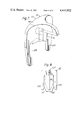
- FIG. 1 is a perspective view of the parts of a first embodiment, which is a two part clip, before assembly;
- FIG. 2 is a perspective view of the almost-completely assembled clip of the first embodiment
- FIG. 3 is and end view of an assembled clip of the first embodiment, mounted on a sleeve
- FIG. 4 is a perspective view of the parts of a second embodiment, which is a three part clip, before assembly;
- FIG. 5 is a perspective view of the almost-completely assembled clip of the second embodiment
- FIGS. 6 and 7 show respectively the two parts of a third embodiment of clip.
- FIG. 8 shows an elevation of the assembled clip of the third embodiment, on a reduced scale.
- the clip 2 of FIGS. 1 and 2 comprises two interengageable parts 4 and 6.
- Part 4 of the clip 2 has three legs 8, 10, 12 that extend generally parallel to each other and generally in a plane away from a closed head portion 14.
- the leg 10 forms respective channels 16 and 18 with the legs 8 and 12 for receiving, in use, circumferentially-spaced portions of an end of a heat-recoverable sleeve on which the clip 2 is mounted, as hereinafter described with reference to FIG. 3.
- a slot 20 is defined along the length of each side of the leg 10 by upstanding portions 22, and the slots 20 are interconnected by a transverse slot 24 extending across the head portion 14 of the clip part 4.
- the central leg 10 of the clip part 4 is coated with hot melt adhesive shown in dotted outline 25 around its entire surface, defining the channels 16 and 18 as longitudinally parallel gaps of width just sufficient to clamp the wall thickness of the associated sleeve, as described with reference to FIG. 3. It will be appreciated that the slots 20 extend into the adhesive 25, being open at the slot 24 and closed by the adhesive at their other ends.
- the part 6 of the clip 2 is generally planar and has four legs 26, 28, 30, 32 extending generally parallel to each other from a transverse head portion 34. Channels 36 and 38 are formed between respective pairs of legs 26, 28, and 30, 32, being tapered inwardly towards the head portion similarly to the channels 16 and 18 of the clip part 4. A further, straight-sided channel or socket 40 extends between the legs 28 and 30.
- the parts 4 and 6 of the clip 2 are assembled (FIG. 2) by sliding the part 6 on to the part 4, with the part 4 located within the central channel 40 of the part 6. (The adhesive 25 is omitted for clarity).
- the legs 28 and 30 slide along respective ones of the slots 20, and the head portion 34 of the part 6 enters the transverse slot 24 of the head portion 14 of the part 4. In the partially-assembled position shown in FIG. 2, the head portion 34 of the part 6 has yet fully to enter the transverse slot 24 of the head portion 14 of the clip part 4.
- a heat-recoverable polymeric tubular sleeve 42 encloses a single telecommunications cable that is divided into four individual, smaller cables 44, 46, 48, 50 at a branch-off joint enclosed by the sleeve 42.
- the cables need not be of the same diameter.
- the clip 2 is mounted over the branch-off end of the sleeve 42, as shown, to divide that outlet of the sleeve 42 into four ducts, each containing a respective one of the cables 44, 46, 48 and 50. To do this, the cables 44 and 46 are separated from the cables 48 and 50, and the sleeve pinched together between the two pairs of cables.
- the clip part 4 is inserted into the end of the sleeve 42 with the channels 16 and 18 enclosing diagonally opposite portions of the circumference of the sleeve 42, and with the leg 10 extending into the sleeve 42, thereby forming two ducts containing the cables 44, 46 and 48, 50 respectively.
- the cables 44 and 46 are then urged towards cables 48 and 50 respectively, and the sleeve 42 pinched to the clip part 4.
- Part 6 of the clip 2 is then slid on to the clip part 4 as described above, with the inner legs 28 and 30 entering the sleeve 42 so as to sub-divide the ducts further, and to position each cable in a respective duct.
- the channels 36 and 38 are guided over diagonally opposite portions of the circumference of the sleeve 42.
- the sleeve 42 is secured by the clip 2 at four circumferentially spaced locations around the cables 44, 46, 48 and 50.
- the sleeve After the clip 2 has been thus assembled on the sleeve 42, the sleeve is heated so that it tends to recover its original configuration and shrinks around the cables.
- the adhesive 25 on the clip 2 enhances sealing around the cables.
- any tendency of the sleeve 42 to pull away from the cables is resisted by the clip 2.
- the tapering of the inner leg 10 and of the channels 36 and 38 allows the clip 2 to be urged properly into the crutch of the cables 44 to 50 adjacent the splice region itself.
- the clip 2 is easy to manufacture, for example by moulding, and also since it comprises only two parts, is inexpensive.
- the clip 52 shown in FIGS. 4 and 5 has three parts, a first part 54 of which has three legs 56, 58 and 60 extending generally parallel to each other from a head-portion 62.
- the leg 58 forms channels 64 and 66 with the legs 56 and 60 respectively.
- the central leg 58 of the clip 52 has one projection 68 extending from each side along the length thereof that has a socket 70 extending therewithin.
- the central leg 58 of the clip part 54 has one projection 68 extending from each side along the length thereof that has a socket 70 extending therewithin.
- the central leg 58 of the clip part 54 is surrounded with adhesive, 71, in a similar manner to that described for the first embodiment, so as to leave the channels 64 and 66 parallel for gripping the sleeve.
- the other two parts 72, 74 of the clip 52 are similar to each other, and each comprises a leg 76 and a spigot 78 extending in the same plane and generally parallel therewithin, being interconnected by a head portion 80.
- the spigots 78 are arranged to be slidably engageable within the sockets 70 of respective projections 68 on each side of the clip part 54, such that the legs 76 lie in a plane extending substantially perpendicularly to the plane containing the legs 54 and 56.
- a block 79 extends from each major surface of the head portion 62 of the clip part 52 and is arranged to engage with a semi-cylindrical extension 81 of the head portion 80 of each clip part 72, 74.
- the clip parts 72 and 74 are slidably engaged with the clip part 52 whilst the legs 76 are at an angle different from 90° to the clip part 52 so that the extensions 81 may pass down beyond the blocks 79.
- the parts 72 and 74 are then rotated into their 90° orientation and are locked longitudinally to the part 52 by interengagement between the blocks 79 and respective extensions 81.
- FIG. 5 shows the clip 52 with the adhesive 71 omitted and with the part 72 already completely engaged with one of the projections 68, and the part 74 only partially entering the socket 70 of the other projection 68.
- the configuration of the assembled clip shown in FIGS. 4 and 5 is generally similar to the configuration of the assembled clip of FIGS. 1 and 2, and can be mounted within a sleeve such as the sleeve 42 of FIG. 3 in similar manner.
- the clip 52 may be easily assembled on the sleeve 42 in three stages, the first being the engagement of the clip part 54 on to the sleeve, followed by individual assembly of the two parts 72 and 74. Furthermore, once the clip parts are interengaged, separation during recovery of the sleeve is positively opposed.
- FIGS. 6 and 7 show the two parts of a further embodiment of a two part clip.
- a first part 82 of the clip has three legs 84, 86 and 88 that define inwardly-tapering channels 90 and 92 between respective pairs of legs 84, 86 and 86, 88 for engagement of circumferentially-spaced portions of a heat recoverable sleeve.
- a bridge portion 94 connects the leg 88 at the closed end of the channel 92 over the end of the leg 86 to a head portion 96 of the part 82, terminating at a transverse planar face 98 thereof.
- the bridge portion 94 has a part-cylindrical upper surface 100 for interengagement with the other part 102 (FIG.
- the clip part 102 has two generally parallel legs 104, 106 interconnected by a head-portion 108.
- the head-portion 108 has a part-rectangular sectioned socket 110 that is shaped to slide laterally over the bridge 94 and its cylindrical surface 100 of the clip part 82 to dispose a planar face 112 of the clip part 102 in abutment with the planar face 98 of the clip part 82 and with the legs 104 and 106 forming respective channels on each side of the leg 86 of the part 82.
- the clip part 82 is mounted over the end of a heat-recoverable member such as the sleeve 42 of FIG. 3, with the leg 86 extending into the sleeve between the cables and with circumferentially-spaced portions of the sleeve disposed within respective channels 90 and 92.
- the clip part 102 is then disposed outside the sleeve 42 astride the leg 88 of the clip part 82.
- the part 102 is then urged towards the head-portion 96 of the part 82, to interlock the two clip parts and to dispose two further circumferentially-spaced portions of the sleeve 42 within the channels formed between the legs 104 and 106 of the clip part 102 and the leg 86 of the clip part 82.
- the sleeve is then shrunk down around the cables.
- the longitudinal surfaces of the central leg 86 of the clip part 82 disposed between the four outer legs of the assembled clip are concave, for example part-cylindrical, so as better to conform to circular-sectioned cables such as the cables shown in FIG. 3. Similar shaping of the inner legs of the clips 2 and 52 is also preferable, as shown.
- FIG. 8 is an elevation of the assembled clip parts 82 and 102 showing the central leg 86 surrounded by hot melt adhesive 114, which provides the channels 90 and 92 as narrow parallel channels for gripping the sleeve.
- FIGS. 6 to 8 The embodiment described with reference to FIGS. 6 to 8 is easy to manufacture by moulding, and is easy to install. Furthermore, there are no longitudinal channels extending along the entire length of the clip, thus eliminating any possible leak paths for moisture into the branch-off or splice within the recovered sleeve.
- clamping member may be provided having two or more parts that can be assembled separately on to a sleeve.
- the clip 52 of FIGS. 4 and 5 may have its outer legs 56 and 60 separable from a suitably-adapted central leg 58 in the same manner as the clip parts 72 and 74.
- Such a construction would allow the central leg of the clip to be inserted between cables within the sleeve at the branch-off and would allow the remaining legs to be added one at a time, simplifying the task of guiding circumferentially-spaced portions of the sleeve into the channels of the clip.
- the clamping member may be formed from or covered with a material that has good chemical and/or electrical resistance.
- the clip shown in FIGS. 6 and 7 may be used where forces on recovery of the sleeve tending to force the two parts of the clip apart longitudinally of the sleeve are relatively high, since this is prevented by the transverse interlocking between the bridge 94 and the socket 110 of the two parts.
- clamping member Whilst the embodiment of clamping member described with reference to FIGS. 6 and 7 inherently has provision for locking the parts together longitudinally of the sleeve, it is envisaged that such locking could also be provided for the parts of other configurations of clamping member.
- the parts constituting the clamping member may not be completely separable.
- parts may be hinged or otherwise movably attached to each other whereby one part or some parts of the member may be fitted over a sleeve before the or other part or parts.
- the part 102 may be arranged to slide away from the part 82 only to the extent necessary to allow the latter part to engage a sleeve without interference from the former part.
- a stop mechanism may be provided between the bridge 94 and the socket 110 for this purpose.
- the parts of the clip disengage longitudinally at least to a length approximately equal to the length of the overlap between the sleeve and the clip leg, for example the central leg, that extends into the sleeve.
Landscapes
- Cable Accessories (AREA)
- Installation Of Indoor Wiring (AREA)
- Protection Of Pipes Against Damage, Friction, And Corrosion (AREA)
- Clamps And Clips (AREA)
- Processing Of Terminals (AREA)
- Seal Device For Vehicle (AREA)
- Electrical Discharge Machining, Electrochemical Machining, And Combined Machining (AREA)
Applications Claiming Priority (2)
| Application Number | Priority Date | Filing Date | Title |
|---|---|---|---|
| GB8016951 | 1980-05-22 | ||
| GB8016951 | 1980-05-22 |
Publications (1)
| Publication Number | Publication Date |
|---|---|
| US4413922A true US4413922A (en) | 1983-11-08 |
Family
ID=10513607
Family Applications (1)
| Application Number | Title | Priority Date | Filing Date |
|---|---|---|---|
| US06/265,733 Expired - Lifetime US4413922A (en) | 1980-05-22 | 1981-05-21 | Branch-off seal |
Country Status (6)
| Country | Link |
|---|---|
| US (1) | US4413922A (da) |
| EP (1) | EP0040957B1 (da) |
| JP (1) | JPS579309A (da) |
| AT (1) | ATE14608T1 (da) |
| DE (1) | DE3171568D1 (da) |
| GB (1) | GB2079072B (da) |
Cited By (6)
| Publication number | Priority date | Publication date | Assignee | Title |
|---|---|---|---|---|
| US4560828A (en) * | 1982-05-11 | 1985-12-24 | Raychem Corporation | Tubular article for branch-off seal |
| US4641402A (en) * | 1982-11-29 | 1987-02-10 | N.V. Raychem S.A. | Branch-off clip and assembly |
| US4689474A (en) * | 1983-05-26 | 1987-08-25 | N.V. Raychem S.A. | Electrically heat-recoverable sleeve |
| US4734543A (en) * | 1978-01-09 | 1988-03-29 | Nolf Jean Marie E | Branch-off assembly |
| US5517592A (en) * | 1993-10-22 | 1996-05-14 | Kabelmetal Electro Gmbh | Sleeve for branch or joint areas in optical or electrical cables |
| US6180887B1 (en) * | 1999-08-10 | 2001-01-30 | Avaya Technology Corp. | Clip for forming a branch off seal and method of using the clip |
Families Citing this family (6)
| Publication number | Priority date | Publication date | Assignee | Title |
|---|---|---|---|---|
| GB8305311D0 (en) * | 1983-02-25 | 1983-03-30 | Raychem Sa Nv | Cable branch-off |
| DE3430088A1 (de) * | 1984-08-16 | 1986-02-27 | Philips Patentverwaltung Gmbh, 2000 Hamburg | Klammer zum einziehen einer schrumpfmuffe bei kabelverzweigungen |
| GB8602668D0 (en) * | 1986-02-04 | 1986-03-12 | Alh Syst Ltd | Forming joints |
| DE3614426A1 (de) * | 1986-04-29 | 1987-11-05 | Minnesota Mining & Mfg | Klammer fuer zwickelbereiche in kabelverbindungen |
| WO1990000470A2 (en) * | 1988-07-05 | 1990-01-25 | Bowthorpe-Hellermann Limited | Forming branch-off enclosures |
| EP0508099B1 (de) * | 1991-03-18 | 1995-03-01 | RXS Schrumpftechnik-Garnituren GmbH | Schrumpfbare Kabelmuffe für Kabel- oder Leitungsabzweige |
Citations (7)
| Publication number | Priority date | Publication date | Assignee | Title |
|---|---|---|---|---|
| DE684743C (de) | 1938-02-23 | 1939-12-04 | Deisting & Co G M B H Dr | Bogenstueck zur Verbindung von Rohren aus Isolierpressstoff mit durchgehenden Kanaelen fuer elektrische Leitungen |
| US3258822A (en) * | 1963-01-28 | 1966-07-05 | Continental Ind Inc | Pipe clamp |
| US3266764A (en) * | 1965-05-04 | 1966-08-16 | Franklin S Briles Inc | Shower pipe hanger |
| US3894706A (en) * | 1972-04-22 | 1975-07-15 | Illinois Tool Works | Tubing clamp assembly for maintaining tubes in locked parallel relationship to surface |
| DE2413623A1 (de) | 1974-03-21 | 1975-10-02 | Rose Walter Kg | Kabelmuffe fuer den anschluss von mindestens zwei zueinander parallelen kabeln |
| US4246687A (en) * | 1978-04-04 | 1981-01-27 | N.V. Raychem S.A. | Branch-off method |
| US4298415A (en) * | 1978-01-09 | 1981-11-03 | N.V. Raychem S.A. | Branch-off method |
-
1981
- 1981-05-21 US US06/265,733 patent/US4413922A/en not_active Expired - Lifetime
- 1981-05-21 AT AT81302250T patent/ATE14608T1/de not_active IP Right Cessation
- 1981-05-21 GB GB8115617A patent/GB2079072B/en not_active Expired
- 1981-05-21 DE DE8181302250T patent/DE3171568D1/de not_active Expired
- 1981-05-21 EP EP81302250A patent/EP0040957B1/en not_active Expired
- 1981-05-22 JP JP7855881A patent/JPS579309A/ja active Granted
Patent Citations (7)
| Publication number | Priority date | Publication date | Assignee | Title |
|---|---|---|---|---|
| DE684743C (de) | 1938-02-23 | 1939-12-04 | Deisting & Co G M B H Dr | Bogenstueck zur Verbindung von Rohren aus Isolierpressstoff mit durchgehenden Kanaelen fuer elektrische Leitungen |
| US3258822A (en) * | 1963-01-28 | 1966-07-05 | Continental Ind Inc | Pipe clamp |
| US3266764A (en) * | 1965-05-04 | 1966-08-16 | Franklin S Briles Inc | Shower pipe hanger |
| US3894706A (en) * | 1972-04-22 | 1975-07-15 | Illinois Tool Works | Tubing clamp assembly for maintaining tubes in locked parallel relationship to surface |
| DE2413623A1 (de) | 1974-03-21 | 1975-10-02 | Rose Walter Kg | Kabelmuffe fuer den anschluss von mindestens zwei zueinander parallelen kabeln |
| US4298415A (en) * | 1978-01-09 | 1981-11-03 | N.V. Raychem S.A. | Branch-off method |
| US4246687A (en) * | 1978-04-04 | 1981-01-27 | N.V. Raychem S.A. | Branch-off method |
Cited By (6)
| Publication number | Priority date | Publication date | Assignee | Title |
|---|---|---|---|---|
| US4734543A (en) * | 1978-01-09 | 1988-03-29 | Nolf Jean Marie E | Branch-off assembly |
| US4560828A (en) * | 1982-05-11 | 1985-12-24 | Raychem Corporation | Tubular article for branch-off seal |
| US4641402A (en) * | 1982-11-29 | 1987-02-10 | N.V. Raychem S.A. | Branch-off clip and assembly |
| US4689474A (en) * | 1983-05-26 | 1987-08-25 | N.V. Raychem S.A. | Electrically heat-recoverable sleeve |
| US5517592A (en) * | 1993-10-22 | 1996-05-14 | Kabelmetal Electro Gmbh | Sleeve for branch or joint areas in optical or electrical cables |
| US6180887B1 (en) * | 1999-08-10 | 2001-01-30 | Avaya Technology Corp. | Clip for forming a branch off seal and method of using the clip |
Also Published As
| Publication number | Publication date |
|---|---|
| DE3171568D1 (en) | 1985-09-05 |
| JPS579309A (en) | 1982-01-18 |
| JPH0258847B2 (da) | 1990-12-10 |
| GB2079072B (en) | 1984-11-28 |
| GB2079072A (en) | 1982-01-13 |
| ATE14608T1 (de) | 1985-08-15 |
| EP0040957B1 (en) | 1985-07-31 |
| EP0040957A1 (en) | 1981-12-02 |
Similar Documents
| Publication | Publication Date | Title |
|---|---|---|
| US4413922A (en) | Branch-off seal | |
| CA1226046A (en) | Cable closure | |
| US5399811A (en) | Device for sealing cables entering a cable coupling sleeve | |
| US3056852A (en) | Strain relief grommet | |
| US4443031A (en) | Connector fitting for connecting corrugated conduit sections | |
| US4117259A (en) | Cable sleeve | |
| US6881901B2 (en) | Connection cover | |
| EP0563164B1 (en) | Electrical connector | |
| US5376196A (en) | Method for sealing the end of a heat-shrunk sleeve | |
| US20150144394A1 (en) | Cable holder | |
| CZ297798B6 (cs) | Zpusob nasunutí a polohování elastického krytu kabelové spojky ve tvaru pouzdra na kabelové spojce a zarízení k jeho provádení | |
| JPH07294765A (ja) | 光学的または電気的ケーブルの分岐点または連結点を収容するための承け口 | |
| US4560828A (en) | Tubular article for branch-off seal | |
| CA2085252C (en) | Harness and cable branch-off | |
| US4203000A (en) | Cable sleeve assembly | |
| EP0094848A2 (en) | Cable joint enclosure | |
| NZ207821A (en) | Cable connector: axially sliding sheath halves | |
| US5335398A (en) | Device for sealing the end of a heat-shrunk sleeve | |
| CA2044585C (en) | Splice closures | |
| EP0236141A2 (en) | Method and device for sealing cables | |
| FI93157B (fi) | Laite kaapelijohdinten liittämiseksi kaukoviestintätekniikan dropwire-liitoslistojen leikkuuliitinkoskettimiin | |
| GB2294597A (en) | Electrical connector | |
| SE462543B (sv) | Anordning foer brandskyddande genomfoering av kablar o.d. i en vaeggoeppning | |
| CA2177446C (en) | Electrical device having adjustable clamping mechanism | |
| GB2061025A (en) | Material for wrapping around pipe, cable or the like |
Legal Events
| Date | Code | Title | Description |
|---|---|---|---|
| AS | Assignment |
Owner name: NV RAYCHEM SA, DIESTSESTEENWEG 692, 3200 KESSEL-LO Free format text: ASSIGNMENT OF ASSIGNORS INTEREST.;ASSIGNOR:NOLF JEAN M. E.;REEL/FRAME:003890/0215 Effective date: 19810520 |
|
| STCF | Information on status: patent grant |
Free format text: PATENTED CASE |
|
| FEPP | Fee payment procedure |
Free format text: PAYOR NUMBER ASSIGNED (ORIGINAL EVENT CODE: ASPN); ENTITY STATUS OF PATENT OWNER: LARGE ENTITY |
|
| MAFP | Maintenance fee payment |
Free format text: PAYMENT OF MAINTENANCE FEE, 4TH YEAR, PL 96-517 (ORIGINAL EVENT CODE: M170); ENTITY STATUS OF PATENT OWNER: LARGE ENTITY Year of fee payment: 4 |
|
| MAFP | Maintenance fee payment |
Free format text: PAYMENT OF MAINTENANCE FEE, 8TH YEAR, PL 96-517 (ORIGINAL EVENT CODE: M171); ENTITY STATUS OF PATENT OWNER: LARGE ENTITY Year of fee payment: 8 |
|
| MAFP | Maintenance fee payment |
Free format text: PAYMENT OF MAINTENANCE FEE, 12TH YEAR, LARGE ENTITY (ORIGINAL EVENT CODE: M185); ENTITY STATUS OF PATENT OWNER: LARGE ENTITY Year of fee payment: 12 |