US4394260A - Control device for a rotary valve-controlled jigging machine - Google Patents
Control device for a rotary valve-controlled jigging machine Download PDFInfo
- Publication number
- US4394260A US4394260A US06/311,873 US31187381A US4394260A US 4394260 A US4394260 A US 4394260A US 31187381 A US31187381 A US 31187381A US 4394260 A US4394260 A US 4394260A
- Authority
- US
- United States
- Prior art keywords
- throttling
- air
- jigging
- valve
- rotary valve
- Prior art date
- Legal status (The legal status is an assumption and is not a legal conclusion. Google has not performed a legal analysis and makes no representation as to the accuracy of the status listed.)
- Expired - Fee Related
Links
Images

Classifications
-
- B—PERFORMING OPERATIONS; TRANSPORTING
- B03—SEPARATION OF SOLID MATERIALS USING LIQUIDS OR USING PNEUMATIC TABLES OR JIGS; MAGNETIC OR ELECTROSTATIC SEPARATION OF SOLID MATERIALS FROM SOLID MATERIALS OR FLUIDS; SEPARATION BY HIGH-VOLTAGE ELECTRIC FIELDS
- B03B—SEPARATING SOLID MATERIALS USING LIQUIDS OR USING PNEUMATIC TABLES OR JIGS
- B03B5/00—Washing granular, powdered or lumpy materials; Wet separating
- B03B5/02—Washing granular, powdered or lumpy materials; Wet separating using shaken, pulsated or stirred beds as the principal means of separation
- B03B5/10—Washing granular, powdered or lumpy materials; Wet separating using shaken, pulsated or stirred beds as the principal means of separation on jigs
- B03B5/24—Constructional details of jigs, e.g. pulse control devices
Definitions
- the present invention relates to a control method and to a control device for a rotary valve-driven jigging machine for processing coal or other minerals, particularly for a rotary valve-driven throughput jigging machine whose pulse chambers are periodically charged with compressed air in order to generate a pulse motion and are disposed below the jigging screen.
- the lift of stroke With jigging machines for processing minerals, the lift of stroke, given a constant excitation intensity, depends on the thickness of the material layer lying on the jigging screen, particularly given throughput jigging machines which are pulsed from below. The cause lies in the attenuating influence of the minerals.
- the object of the present invention is to provide a control device for a jigging machine in which an accurate observation of the size of the set stroke of the separating liquid is achieved, in contrast thereto, even given differing mineral layer heights on the jigging machine bed.
- the level of the working air pressure in the pulse chambers is changed as a function of changes of the size of the stroke of the separating liquid. Therefore, that magnitude in the jigging process whose influencing most greatly changes the separating result is advantageously taken as the regulating variable. Further, an optimum operating point which has once been set can be maintained with certainty.
- the control can directly react to all changes of the stroke motion.
- the change of the level of the working air pressure in the pulse chambers occurs by a controlled throttling of the outgoing air. Therefore, a particularly simple change of the level of the working air pressure can be achieved without changes being necessary at the jigging machine.
- the change of the level of the working air pressure in the pulse chambers occurs by a controlled throttling of the outgoing air and incoming air.
- An additional throttling of the incoming air is provided when great fluctuations of the charging rate of the minerals make great changes of the working air pressure necessary in order to maintain the optimum stroke.
- the size of the stroke of the separating liquid is continuously measured by at least one measuring device, being preferably electrically measured.
- an electrical measurement for example with the assistance of a probe, there derives a particularly accurate determination of the respective lift stroke which is far superior in terms of accuracy to a mechanical sensing.
- the size of the stroke of the separating liquid is maintained constant within prescribed limiting values and that the control of the size of the stroke of the separating liquid occurs automatically with the assistance of an electronic control system. Due to the employment of metal-oxide-semiconductor (MOS) modules in integrated circuits, electronic control systems are very reliable. At the same time, such a control is possible with previously-unattainable accuracy given immediate response. Overall, there is provided a control of a jigging machine, according to the present invention, which operates very accurately, responds immediately and exhibits a high degree of availability.
- MOS metal-oxide-semiconductor
- a rotary valve-driven jigging machine having pulse chambers disposed below the jigging screen is provided, exhibiting a throttling valve in the outgoing air and/or in the incoming air line which is connected to a control system.
- the jigging machine has at least one probe per pulse chamber. With a probe in a respective pulse chamber, the pulse motion is measured at a particularly protected location at which no disruptions can occur due to the sinks.
- the pulse chamber and the jigging space are connected to one another in the manner of communicating pipes, so that a measurement of the pulse motion in the air chambers indicates the pulse motion on the jigging bed considering the respective translation of water motions due to different cross-sections.
- the accuracy of the control is thereby further increased by the arrangement of the probe in the pulse chambers, since the water path is greater here than on the jigging bed.
- the probes are connected to an electronic limiting value switch system, such as threshold switches. Therefore, the probe measurement can be advantageously employed for the control without time delay.
- a limiting value switch system is thereby particularly advantageous since it allows the machine to run within the limits of the optimum pulse range without control operations and allows control operations only given fluctuations which would influence the jigging result. Therefore, the number of control operations is significantly reduced.
- control valves are designed as conical valves, particularly with a linear characteristic. By so doing, the control is particularly simplified.
- the throttle valves are employed which are particularly insensitive to contamination, etc.
- the incoming air and the outgoing air throttle valve are mechanically and adjustably connected to one another. The mechanical connection of the valves, which is particularly designed in such a manner that the motion of the outgoing throttle valve amounts to a multiple of that of the incoming throttle valve, considerably simplifies the control of the two-valve throttle system.
- FIG. 1 is a schematic illustration of a jigging machine compartment of a throughput jigging machine having an electronic limiting value switch system constructed in accordance with the present invention
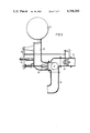
- FIG. 2 is an illustration, partially in section, of a conical valve in an outgoing airline
- FIG. 3 is an illustration, again partially in section, of an incoming air valve and an outgoing air valve which are mechanically coupled to one another.
- a jigging machine compartment 1 of a throughput jigging machine includes a pulse chamber 2 and a pair of working air intakes and discharges 3.
- a probe 4 for example a capacitively or inductively operating bar probe, whose signal 4' is forwarded to a transmitter 5 (an amplifier) is disposed in the pulse chamber 2.
- the jigging screen 6' is disposed above the pulse chamber 2 with a layer of weld spar 6 being located on the jigging screen 6' through which the heavy components of the mineral mixture settled toward the bottom in order to be withdrawn, the screen structure being perforate, from the lower portion of the jigging compartment 1.
- the transmitter 5 generates a signal 5' in response to the signal 4', the signal 5' being fed to a limit or threshold value switch 8 for the upper limiting value and to a threshold or limiting value switch 9 for the lower limiting value.
- the switches 8 and 9 may be simple threshold-responsive switches and may comprise, for example, Schmitt trigger circuits.
- the analog response 4' of the probe 4 has therefore been converted to digital signals at the outputs of the threshold value switches 8 and 9.
- the limiting value switches 8 and 9 emit signals 8' and 9', respectively, which are fed to respective AND gates 10 and 11.
- the AND gates 10 and 11 are also fed with a signal 7' which indicates that the valve control, for example the rotary valve control unit, is started up and a signal 7" which indicates that compressed air is being provided at the rotary valve control.
- the signal 8' for the upper limiting value is produced and a signal 9' for the lower limiting value is produced and fed from the respective AND gates as signals 10' and 11' to a motor switch 12 which actuates a motor operator 13.
- the element 13 is a servomotor and has an output shaft 30 which reports its position back to the motor switch 12 by way of an answer control loop 14, 15.
- the output shaft of the motor 13, which may be an electromagnetic, linearly operating setting system instead, actuates a discharge throttle valve which is illustrated in greater detail in FIG. 2.
- an air dome 16 is illustrated for storing working air and is connected by way of a line 17 to a rotary valve.
- 20 and 21 respectively indicate the working airline from the rotary valve to the pulse chamber (not illustrated) and the rotary valve.
- the adjustable throttle valve 18, preferably a conical valve, is disposed in the discharge line, the throttle valve 18 being actuated by way of the setting device and the schematically indicated setting motor shaft 30, for example the output shaft of the drive motor 13 illustrated in FIG. 1.
- the air dome 16 is again illustrated as connected in communication with a rotary valve 21 via a line 22.
- a conical valve 26 and a conical valve 27 are built into the supply line 23 and into the discharge line 24, respectively.
- the two valves are advantageously connected to one another via a mechanical setting system which can be adjusted in terms of motion transmission and which is provided with oscillation dampers, etc.
- the actuation of the setting system 25 occurs via the setting arm 31, which may correspond to the output shaft 30 of the motor 13 or an equivalent linear-operating structure.
- the double-valve embodiment is particularly suited for jigging machines having high-charging fluctuations of the jigging material.
- the control described above with respect to the present invention has particularly been developed for small coal jigging machines. It can, however, be employed for all throughput jigging machines and for discharge jigging machines as well. The fact that the optimum jigging stroke is observed, even given fluctuating charging amounts, is always achieved. The type of mineral to be separated and the type of the discharge do not influence the control.
Landscapes
- Separation Of Solids By Using Liquids Or Pneumatic Power (AREA)
- Electrically Driven Valve-Operating Means (AREA)
- Flow Control (AREA)
- Reciprocating Pumps (AREA)
Applications Claiming Priority (2)
| Application Number | Priority Date | Filing Date | Title |
|---|---|---|---|
| DE19803038921 DE3038921A1 (de) | 1980-10-15 | 1980-10-15 | Regelverfahren und regelvorrichtung fuer eine drehschieber-gesteuerte setzmaschine |
| DE3038921 | 1980-10-15 |
Publications (1)
| Publication Number | Publication Date |
|---|---|
| US4394260A true US4394260A (en) | 1983-07-19 |
Family
ID=6114434
Family Applications (1)
| Application Number | Title | Priority Date | Filing Date |
|---|---|---|---|
| US06/311,873 Expired - Fee Related US4394260A (en) | 1980-10-15 | 1981-10-15 | Control device for a rotary valve-controlled jigging machine |
Country Status (5)
| Country | Link |
|---|---|
| US (1) | US4394260A (member.php) |
| JP (1) | JPS5791754A (member.php) |
| DE (1) | DE3038921A1 (member.php) |
| FR (1) | FR2491781A1 (member.php) |
| GB (1) | GB2085322A (member.php) |
Cited By (3)
| Publication number | Priority date | Publication date | Assignee | Title |
|---|---|---|---|---|
| CN1046101C (zh) * | 1993-03-04 | 1999-11-03 | 兖州矿务局鲍店煤矿 | 选煤厂跳汰机供风系统 |
| US20110284093A1 (en) * | 2010-04-27 | 2011-11-24 | Mbe Coal & Minerals Technology Gmbh | Method for controlling a jigging machine |
| US20180038291A1 (en) * | 2016-08-04 | 2018-02-08 | Ford Global Technologies, Llc | Throttle valve assembly |
Families Citing this family (3)
| Publication number | Priority date | Publication date | Assignee | Title |
|---|---|---|---|---|
| DE3221511A1 (de) * | 1982-06-07 | 1983-12-08 | Klöckner-Humboldt-Deutz AG, 5000 Köln | Klappenventil fuer eine nass-setzmaschine zur aufbereitung von kohle oder sonstigen mineralien |
| DE3237248C2 (de) * | 1982-10-07 | 1987-05-14 | Vorošilovgradskij filial gosudarstvennogo proektno-konstruktorskogo i naučno-issledovatel'skogo instituta po avtomatizacii ugol'noj promyšlennosti "Giprougleavtomatizacija", Vorošilovgrad | Verfahren und Einrichtung zur Regelung des pulsierenden Setzwasserstroms in Naßsetzmaschinen |
| AUPN531995A0 (en) * | 1995-09-08 | 1995-10-05 | University Of Queensland, The | Dynamic monitoring and control of jigs |
Citations (10)
| Publication number | Priority date | Publication date | Assignee | Title |
|---|---|---|---|---|
| US901474A (en) * | 1905-08-02 | 1908-10-20 | Robert Hallowell Richards | Apparatus for separating and classifying minerals. |
| US2052431A (en) * | 1934-02-26 | 1936-08-25 | Henry H Wade | Apparatus for concentrating ores |
| US2811257A (en) * | 1954-05-14 | 1957-10-29 | American Chrome Company | Automatic control for maintaining constant density in hydraulic classifier |
| US2828015A (en) * | 1953-11-30 | 1958-03-25 | Gustave A Vissac | Jig separator |
| US3073450A (en) * | 1958-10-09 | 1963-01-15 | Saarbergwerke Ag | Apparatus for use in coal washing tanks |
| DE1197822B (de) * | 1964-11-12 | 1965-08-05 | Schuechtermann & Kremer | Vorrichtung zum UEberwachen der Gutzufuhr zu Setzmaschinen mit unterhalb des Setzsiebes angeordneten Pulskammern |
| DE2411386A1 (de) * | 1974-03-09 | 1975-09-18 | Kloeckner Humboldt Deutz Ag | Verfahren und vorrichtung zur regelung einer setzmaschine fuer die aufbereitung von mineralien, insbesondere kohle |
| US4176749A (en) * | 1977-01-15 | 1979-12-04 | Nortn-Harty Colliery Engineering Limited | Materials separation |
| US4264441A (en) * | 1978-05-26 | 1981-04-28 | Klockner-Humboldt-Deutz Ag | Automatic control for electro-pneumatic wet settling |
| DE2539374C2 (de) | 1975-09-04 | 1982-12-02 | Klöckner-Humboldt-Deutz AG, 5000 Köln | Verfahren und Vorrichtung zur Aufbereitung von Mineralgemischen, insbesondere von Rohwaschkohle auf einer druckluftgesteuerten Naßsetzmaschine |
Family Cites Families (1)
| Publication number | Priority date | Publication date | Assignee | Title |
|---|---|---|---|---|
| DE2527756A1 (de) * | 1975-06-21 | 1977-01-13 | Kloeckner Humboldt Deutz Ag | Verfahren zum anfahren von luftgesteuerten nassetzmaschinen und vorrichtung zur durchfuehrung des verfahrens |
-
1980
- 1980-10-15 DE DE19803038921 patent/DE3038921A1/de not_active Withdrawn
-
1981
- 1981-10-14 JP JP56162895A patent/JPS5791754A/ja active Pending
- 1981-10-14 FR FR8119334A patent/FR2491781A1/fr active Granted
- 1981-10-15 GB GB8131160A patent/GB2085322A/en not_active Withdrawn
- 1981-10-15 US US06/311,873 patent/US4394260A/en not_active Expired - Fee Related
Patent Citations (10)
| Publication number | Priority date | Publication date | Assignee | Title |
|---|---|---|---|---|
| US901474A (en) * | 1905-08-02 | 1908-10-20 | Robert Hallowell Richards | Apparatus for separating and classifying minerals. |
| US2052431A (en) * | 1934-02-26 | 1936-08-25 | Henry H Wade | Apparatus for concentrating ores |
| US2828015A (en) * | 1953-11-30 | 1958-03-25 | Gustave A Vissac | Jig separator |
| US2811257A (en) * | 1954-05-14 | 1957-10-29 | American Chrome Company | Automatic control for maintaining constant density in hydraulic classifier |
| US3073450A (en) * | 1958-10-09 | 1963-01-15 | Saarbergwerke Ag | Apparatus for use in coal washing tanks |
| DE1197822B (de) * | 1964-11-12 | 1965-08-05 | Schuechtermann & Kremer | Vorrichtung zum UEberwachen der Gutzufuhr zu Setzmaschinen mit unterhalb des Setzsiebes angeordneten Pulskammern |
| DE2411386A1 (de) * | 1974-03-09 | 1975-09-18 | Kloeckner Humboldt Deutz Ag | Verfahren und vorrichtung zur regelung einer setzmaschine fuer die aufbereitung von mineralien, insbesondere kohle |
| DE2539374C2 (de) | 1975-09-04 | 1982-12-02 | Klöckner-Humboldt-Deutz AG, 5000 Köln | Verfahren und Vorrichtung zur Aufbereitung von Mineralgemischen, insbesondere von Rohwaschkohle auf einer druckluftgesteuerten Naßsetzmaschine |
| US4176749A (en) * | 1977-01-15 | 1979-12-04 | Nortn-Harty Colliery Engineering Limited | Materials separation |
| US4264441A (en) * | 1978-05-26 | 1981-04-28 | Klockner-Humboldt-Deutz Ag | Automatic control for electro-pneumatic wet settling |
Cited By (3)
| Publication number | Priority date | Publication date | Assignee | Title |
|---|---|---|---|---|
| CN1046101C (zh) * | 1993-03-04 | 1999-11-03 | 兖州矿务局鲍店煤矿 | 选煤厂跳汰机供风系统 |
| US20110284093A1 (en) * | 2010-04-27 | 2011-11-24 | Mbe Coal & Minerals Technology Gmbh | Method for controlling a jigging machine |
| US20180038291A1 (en) * | 2016-08-04 | 2018-02-08 | Ford Global Technologies, Llc | Throttle valve assembly |
Also Published As
| Publication number | Publication date |
|---|---|
| JPS5791754A (en) | 1982-06-08 |
| FR2491781B3 (member.php) | 1983-08-05 |
| FR2491781A1 (fr) | 1982-04-16 |
| GB2085322A (en) | 1982-04-28 |
| DE3038921A1 (de) | 1982-06-03 |
Similar Documents
| Publication | Publication Date | Title |
|---|---|---|
| CA1209481A (en) | Fuel mass flow measurement and control system | |
| CA1133606A (en) | Method and apparatus for determining the thickness of a charge wall formed in a centrifugal basket | |
| EP1529202B1 (de) | Vorrichtung zur überwachung eines vorbestimmten füllstands eines messmediums in einem behälter | |
| US4394260A (en) | Control device for a rotary valve-controlled jigging machine | |
| US5321601A (en) | Apparatus for controlling flow in a sewer regulator | |
| RU2005106195A (ru) | Способ управления сортировочной машиной и сортировочная машина | |
| CA2212484C (en) | Method and apparatus for controlling water addition to grains | |
| GB2030327A (en) | Controlling the flow of textile fibres | |
| US4748365A (en) | Method and apparatus for supplying electric power to a vibration generator transducer | |
| US3291233A (en) | Weighing apparatus | |
| US4265744A (en) | Discharge-controlled method for a compressed air-controlled wet settling machine | |
| US3719090A (en) | Method and apparatus for measurement of particle size and percent solids in multiple process flowstreams | |
| US2950177A (en) | Apparatus for the determination and control of compositions in chemical processes | |
| GB1161810A (en) | Vibration Monitoring System. | |
| US2919573A (en) | Apparatus for measuring fiber permeability | |
| US3521696A (en) | Continuous casting line speed control | |
| US3228863A (en) | Electrolytic process and apparatus for removing stock from a conductive workpiece | |
| KR930008378B1 (ko) | 방전 절단장치 및 그 작업변수의 제어방법 | |
| GB996337A (en) | Improvements in or relating to hydraulic servo-mechanisms | |
| US4840704A (en) | Controlling characteristics of a pulp mat on a pulp washing surface | |
| GB1604139A (en) | Automatic control method for electro-pneumatic wet jigging machines designed to separate mineral mixtures more particularly coal | |
| EP0171403B1 (en) | Means for measuring milk obtained by milking | |
| US4433945A (en) | Method and apparatus for controlling a mine roof support | |
| DE2653636A1 (de) | Walzenmuehle | |
| GB1283083A (en) | Electro-chemical grinding process |
Legal Events
| Date | Code | Title | Description |
|---|---|---|---|
| AS | Assignment |
Owner name: KLOCKNER-HUMBOLDT DEUTZ AKTIENGESELLSCHAFT, GERMAN Free format text: ASSIGNMENT OF ASSIGNORS INTEREST;ASSIGNORS:HEINTGES, SIEGFRIED;STRAUSS, WERNER;WEIFFEN, KARL-HEINZ;SIGNING DATES FROM 19810922 TO 19811015;REEL/FRAME:003966/0126 Owner name: KLOCKNER-HUMBOLDT DEUTZ AKTIENGESELLSCHAFT, A CORP Free format text: ASSIGNMENT OF ASSIGNORS INTEREST.;ASSIGNORS:HEINTGES, SIEGFRIED;STRAUSS, WERNER;WEIFFEN, KARL-HEINZ;REEL/FRAME:003966/0126;SIGNING DATES FROM 19810922 TO 19811015 |
|
| FEPP | Fee payment procedure |
Free format text: MAINTENANCE FEE REMINDER MAILED (ORIGINAL EVENT CODE: REM.); ENTITY STATUS OF PATENT OWNER: LARGE ENTITY |
|
| LAPS | Lapse for failure to pay maintenance fees | ||
| STCH | Information on status: patent discontinuation |
Free format text: PATENT EXPIRED DUE TO NONPAYMENT OF MAINTENANCE FEES UNDER 37 CFR 1.362 |
|
| FP | Lapsed due to failure to pay maintenance fee |
Effective date: 19870719 |