US4336066A - Method for manufacturing components for magnetic heads of increased abrasion resistance - Google Patents
Method for manufacturing components for magnetic heads of increased abrasion resistance Download PDFInfo
- Publication number
- US4336066A US4336066A US06/152,782 US15278280A US4336066A US 4336066 A US4336066 A US 4336066A US 15278280 A US15278280 A US 15278280A US 4336066 A US4336066 A US 4336066A
- Authority
- US
- United States
- Prior art keywords
- weight
- carried out
- atomization
- annealing
- powder
- Prior art date
- Legal status (The legal status is an assumption and is not a legal conclusion. Google has not performed a legal analysis and makes no representation as to the accuracy of the status listed.)
- Expired - Lifetime
Links
- 238000005299 abrasion Methods 0.000 title claims abstract description 50
- 238000004519 manufacturing process Methods 0.000 title claims abstract description 13
- 238000000034 method Methods 0.000 title claims description 32
- 239000000843 powder Substances 0.000 claims abstract description 75
- 239000000463 material Substances 0.000 claims abstract description 67
- 229910045601 alloy Inorganic materials 0.000 claims abstract description 38
- 239000000956 alloy Substances 0.000 claims abstract description 38
- 229910000889 permalloy Inorganic materials 0.000 claims abstract description 31
- 239000000203 mixture Substances 0.000 claims abstract description 26
- 238000000137 annealing Methods 0.000 claims abstract description 24
- 238000000889 atomisation Methods 0.000 claims abstract description 24
- 238000005096 rolling process Methods 0.000 claims abstract description 15
- 238000005245 sintering Methods 0.000 claims description 18
- 238000005056 compaction Methods 0.000 claims description 16
- UFHFLCQGNIYNRP-UHFFFAOYSA-N Hydrogen Chemical compound [H][H] UFHFLCQGNIYNRP-UHFFFAOYSA-N 0.000 claims description 7
- 238000010438 heat treatment Methods 0.000 claims description 7
- 239000001257 hydrogen Substances 0.000 claims description 7
- 229910052739 hydrogen Inorganic materials 0.000 claims description 7
- 239000007789 gas Substances 0.000 claims description 5
- 230000002706 hydrostatic effect Effects 0.000 claims description 5
- 238000005097 cold rolling Methods 0.000 claims description 4
- 239000011261 inert gas Substances 0.000 claims description 3
- 238000009689 gas atomisation Methods 0.000 claims description 2
- 238000000227 grinding Methods 0.000 claims 1
- 239000002245 particle Substances 0.000 abstract description 20
- 230000015572 biosynthetic process Effects 0.000 abstract description 6
- 239000006185 dispersion Substances 0.000 abstract description 5
- 238000004663 powder metallurgy Methods 0.000 abstract description 5
- 238000012360 testing method Methods 0.000 description 39
- 239000000523 sample Substances 0.000 description 26
- 238000005259 measurement Methods 0.000 description 16
- XEEYBQQBJWHFJM-UHFFFAOYSA-N iron Substances [Fe] XEEYBQQBJWHFJM-UHFFFAOYSA-N 0.000 description 10
- PXHVJJICTQNCMI-UHFFFAOYSA-N nickel Substances [Ni] PXHVJJICTQNCMI-UHFFFAOYSA-N 0.000 description 10
- 238000002360 preparation method Methods 0.000 description 10
- 230000009467 reduction Effects 0.000 description 9
- 230000008859 change Effects 0.000 description 8
- 230000004907 flux Effects 0.000 description 8
- 230000035699 permeability Effects 0.000 description 8
- 229920006395 saturated elastomer Polymers 0.000 description 8
- 239000010936 titanium Substances 0.000 description 7
- 230000006872 improvement Effects 0.000 description 5
- 238000002156 mixing Methods 0.000 description 5
- 229910052719 titanium Inorganic materials 0.000 description 5
- XKRFYHLGVUSROY-UHFFFAOYSA-N Argon Chemical compound [Ar] XKRFYHLGVUSROY-UHFFFAOYSA-N 0.000 description 4
- 229910052742 iron Inorganic materials 0.000 description 4
- 238000010309 melting process Methods 0.000 description 4
- 229910052759 nickel Inorganic materials 0.000 description 4
- 230000008569 process Effects 0.000 description 4
- QVGXLLKOCUKJST-UHFFFAOYSA-N atomic oxygen Chemical compound [O] QVGXLLKOCUKJST-UHFFFAOYSA-N 0.000 description 3
- 230000000694 effects Effects 0.000 description 3
- 229920001971 elastomer Polymers 0.000 description 3
- 238000007254 oxidation reaction Methods 0.000 description 3
- 239000001301 oxygen Substances 0.000 description 3
- 229910052760 oxygen Inorganic materials 0.000 description 3
- 229910052786 argon Inorganic materials 0.000 description 2
- 230000008901 benefit Effects 0.000 description 2
- 238000005266 casting Methods 0.000 description 2
- 230000002542 deteriorative effect Effects 0.000 description 2
- 229910044991 metal oxide Inorganic materials 0.000 description 2
- 150000004706 metal oxides Chemical class 0.000 description 2
- 239000010955 niobium Substances 0.000 description 2
- 230000003647 oxidation Effects 0.000 description 2
- 239000011347 resin Substances 0.000 description 2
- 229920005989 resin Polymers 0.000 description 2
- 239000007787 solid Substances 0.000 description 2
- 239000000126 substance Substances 0.000 description 2
- 229910052684 Cerium Inorganic materials 0.000 description 1
- VYZAMTAEIAYCRO-UHFFFAOYSA-N Chromium Chemical compound [Cr] VYZAMTAEIAYCRO-UHFFFAOYSA-N 0.000 description 1
- RYGMFSIKBFXOCR-UHFFFAOYSA-N Copper Chemical compound [Cu] RYGMFSIKBFXOCR-UHFFFAOYSA-N 0.000 description 1
- 229910000616 Ferromanganese Inorganic materials 0.000 description 1
- 229910000519 Ferrosilicon Inorganic materials 0.000 description 1
- 229910001145 Ferrotungsten Inorganic materials 0.000 description 1
- 229910000628 Ferrovanadium Inorganic materials 0.000 description 1
- 229910001030 Iron–nickel alloy Inorganic materials 0.000 description 1
- 229910001257 Nb alloy Inorganic materials 0.000 description 1
- 229910003271 Ni-Fe Inorganic materials 0.000 description 1
- 229910001362 Ta alloys Inorganic materials 0.000 description 1
- 239000000654 additive Substances 0.000 description 1
- 230000000996 additive effect Effects 0.000 description 1
- 125000002915 carbonyl group Chemical group [*:2]C([*:1])=O 0.000 description 1
- 239000011651 chromium Substances 0.000 description 1
- GUTLYIVDDKVIGB-UHFFFAOYSA-N cobalt atom Chemical compound [Co] GUTLYIVDDKVIGB-UHFFFAOYSA-N 0.000 description 1
- 230000002301 combined effect Effects 0.000 description 1
- 238000007796 conventional method Methods 0.000 description 1
- 239000010949 copper Substances 0.000 description 1
- 238000005520 cutting process Methods 0.000 description 1
- 238000011161 development Methods 0.000 description 1
- 229910052595 hematite Inorganic materials 0.000 description 1
- 239000011019 hematite Substances 0.000 description 1
- LIKBJVNGSGBSGK-UHFFFAOYSA-N iron(3+);oxygen(2-) Chemical compound [O-2].[O-2].[O-2].[Fe+3].[Fe+3] LIKBJVNGSGBSGK-UHFFFAOYSA-N 0.000 description 1
- 239000011572 manganese Substances 0.000 description 1
- 238000002844 melting Methods 0.000 description 1
- 230000008018 melting Effects 0.000 description 1
- 238000000926 separation method Methods 0.000 description 1
- 238000007493 shaping process Methods 0.000 description 1
- XLYOFNOQVPJJNP-UHFFFAOYSA-N water Substances O XLYOFNOQVPJJNP-UHFFFAOYSA-N 0.000 description 1
Images


Classifications
-
- H—ELECTRICITY
- H01—ELECTRIC ELEMENTS
- H01F—MAGNETS; INDUCTANCES; TRANSFORMERS; SELECTION OF MATERIALS FOR THEIR MAGNETIC PROPERTIES
- H01F41/00—Apparatus or processes specially adapted for manufacturing or assembling magnets, inductances or transformers; Apparatus or processes specially adapted for manufacturing materials characterised by their magnetic properties
- H01F41/14—Apparatus or processes specially adapted for manufacturing or assembling magnets, inductances or transformers; Apparatus or processes specially adapted for manufacturing materials characterised by their magnetic properties for applying magnetic films to substrates
- H01F41/16—Apparatus or processes specially adapted for manufacturing or assembling magnets, inductances or transformers; Apparatus or processes specially adapted for manufacturing materials characterised by their magnetic properties for applying magnetic films to substrates the magnetic material being applied in the form of particles, e.g. by serigraphy, to form thick magnetic films or precursors therefor
-
- G—PHYSICS
- G11—INFORMATION STORAGE
- G11B—INFORMATION STORAGE BASED ON RELATIVE MOVEMENT BETWEEN RECORD CARRIER AND TRANSDUCER
- G11B5/00—Recording by magnetisation or demagnetisation of a record carrier; Reproducing by magnetic means; Record carriers therefor
- G11B5/10—Structure or manufacture of housings or shields for heads
- G11B5/11—Shielding of head against electric or magnetic fields
-
- G—PHYSICS
- G11—INFORMATION STORAGE
- G11B—INFORMATION STORAGE BASED ON RELATIVE MOVEMENT BETWEEN RECORD CARRIER AND TRANSDUCER
- G11B5/00—Recording by magnetisation or demagnetisation of a record carrier; Reproducing by magnetic means; Record carriers therefor
- G11B5/127—Structure or manufacture of heads, e.g. inductive
-
- Y—GENERAL TAGGING OF NEW TECHNOLOGICAL DEVELOPMENTS; GENERAL TAGGING OF CROSS-SECTIONAL TECHNOLOGIES SPANNING OVER SEVERAL SECTIONS OF THE IPC; TECHNICAL SUBJECTS COVERED BY FORMER USPC CROSS-REFERENCE ART COLLECTIONS [XRACs] AND DIGESTS
- Y10—TECHNICAL SUBJECTS COVERED BY FORMER USPC
- Y10S—TECHNICAL SUBJECTS COVERED BY FORMER USPC CROSS-REFERENCE ART COLLECTIONS [XRACs] AND DIGESTS
- Y10S428/00—Stock material or miscellaneous articles
- Y10S428/90—Magnetic feature
-
- Y—GENERAL TAGGING OF NEW TECHNOLOGICAL DEVELOPMENTS; GENERAL TAGGING OF CROSS-SECTIONAL TECHNOLOGIES SPANNING OVER SEVERAL SECTIONS OF THE IPC; TECHNICAL SUBJECTS COVERED BY FORMER USPC CROSS-REFERENCE ART COLLECTIONS [XRACs] AND DIGESTS
- Y10—TECHNICAL SUBJECTS COVERED BY FORMER USPC
- Y10S—TECHNICAL SUBJECTS COVERED BY FORMER USPC CROSS-REFERENCE ART COLLECTIONS [XRACs] AND DIGESTS
- Y10S428/00—Stock material or miscellaneous articles
- Y10S428/922—Static electricity metal bleed-off metallic stock
- Y10S428/9265—Special properties
- Y10S428/928—Magnetic property
-
- Y—GENERAL TAGGING OF NEW TECHNOLOGICAL DEVELOPMENTS; GENERAL TAGGING OF CROSS-SECTIONAL TECHNOLOGIES SPANNING OVER SEVERAL SECTIONS OF THE IPC; TECHNICAL SUBJECTS COVERED BY FORMER USPC CROSS-REFERENCE ART COLLECTIONS [XRACs] AND DIGESTS
- Y10—TECHNICAL SUBJECTS COVERED BY FORMER USPC
- Y10T—TECHNICAL SUBJECTS COVERED BY FORMER US CLASSIFICATION
- Y10T29/00—Metal working
- Y10T29/49—Method of mechanical manufacture
- Y10T29/49002—Electrical device making
- Y10T29/4902—Electromagnet, transformer or inductor
- Y10T29/49075—Electromagnet, transformer or inductor including permanent magnet or core
- Y10T29/49078—Laminated
Definitions
- the present invention relates to a method for manufacturing components for magnetic heads, and more particularly relates to improvements in the method for manufacturing components such as a core and a shield casing for magnetic heads used for magnetic sound or video recording and reproducing.
- the material used for the above-described components is in general required to have, in addition to high magnetic properties, high mechanical properties, in particular high abrasion resistance since they are usually subjected to hard and frequent frictional contact with running magnetic tapes.
- Permalloy alloys are conventionally and generally used for such components but unable to sufficiently suffice such requirement for high abrasion resistance, thereby causing relatively low durability of these components for magnetic heads. It is proposed to add a particular element or elements to permalloy alloys. Such addition, however, is still unable to raise abrasion resistance of the component to an appreciable extent, and liable to lower magnetic characteristics of the product. It is proposed also to add a hard material or materials such as metal oxide to permalloy alloy. This addition, however, is accompanied with difficulty in uniform dispersion of the added material into the base alloy even in molten state. Biased presence of the added material in the base alloy naturally causes biased mechanical and/or magnetic properties of the product.
- the inventors of the present invention has tried to greatly raise abrasion resistance of the components used for magnetic heads by improving their manufacturing method.
- a cast block is reformed into laminae by rolling.
- the present invention proposes to introduce the art of powder metallurgy into the above-described manufacturing in order to obtain permalloy alloy blocks to be subsequently subjected to rolling. It is admitted that mere manufacturing of permalloy alloy block by powder metallurgy itself is an established art well known to public. However, permalloy alloy blocks manufactured by powder metallurgy only have very poor abrasion resistance. Further, presence of numerous fine air voids in the block disables easy application of fine cutting to the block and deteriorates magnetic properties of the product.
- material powder is blended so as to substantially have a permalloy alloy composition, the blended material powder is subjected to compaction to obtain a compressed block, and the compressed block is subjected to rolling after application of sintering.
- blending of the material powder is carried out by mixing Fe powder with Ni powder.
- Fe-Ni alloy powder may be used as the base material with addition of a proper material or materials for improving any property of the product.
- So-called 78 permalloy may be used for the permalloy alloy in the present invention.
- 78-permalloy includes, as the base material, a mixture of 60 to 90% by weight of Ni with 5 to 20% by weight of Fe.
- the base material it may include, depending on requirement in use of the product, at least one of 0.5 to 14% by weight of Mo, 0.1 to 20% by weight of Cu, 0.1 to 10% by weight of Cr, 0.1 to 15% by weight of Nb, 0.1 to 10% by weight of Ti, 0.1 to 8% by weight of V, 0.1 to 8% by weight of Si, 0.01 to 5% by weight of Al, 0.1 to 8% by weight of W, 0.1 to 15% by weight of Ta, 0.01 to 15% by weight of Mn, 0.1 to 5 % by weight of Co, 0.005 to 5% by weight of Y, 0.005 to 5% by weight of Ce, 0.005 to 5% by weight of La and 0.005 to 5% by weight of Sm.
- So-called 45-permalloy may be usable also, which includes, as the base material, a mixture of 35 to 55% by weight of Ni, with 35 to 55% by weight of Fe, and, as the additive, at least one of the above-described materials.
- the material powder is placed, for example, in a rubber casing for compaction by, for example, hydrostatic compaction.
- hydrostatic compaction the compaction pressure should preferably be in a range from 4,000 to 20,000 kg/cm 2 and the compaction time in a range from 2 to 300 sec.
- the compressed block obtained by the compaction is then subjected to high temperature sintering within a vacuum, reducing gas or inert gas atmosphere.
- the degree of vacuum should preferably be 10 -2 Torr or lower. Any degree of vacuum above limit tends to cause oxidation of the material powder, thereby deteriorating magnetic properties of the product.
- the dew point of the gas should preferably be -20° C. or lower. Any dew point exceeding this value may also cause oxidation of the material powder, thereby lowering magnetic properties of the product.
- the sintering temperature should preferably be in a range from 900° to 1,430° C. No effective sintering starts at a temperature below 900° C. whereas any temperature above 1.430° C. may cause melting of the material powder.
- the sintering time should preferably be in a range from 1 to 20 hours. No sufficient sintering effect is obtained when heating lasts shorter than 1 hour whereas no remarkable rise in sintering effect is expected when heating time exceeds 20 hours.
- the sintered block is rolled into a lamina of, for example, about 0.3 mm thickness.
- This rolling preferably includes alternate application of 30 to 70% of cold rollings and annealings at 750° to 850° C.
- the lamina so obtained is then cut into laminae of a prescribed pattern.
- laminae are superposed upon each other and bonded together by suitable resin.
- the lamina is subjected to pressure shaping.
- permalloy powder metallurgy is used in combination with the later-staged rolling, thereby successfully raising abrasion resistance of the product.
- This success accrues from the fact that application of the rolling smashes hard oxidized shells formed on powder particles during the initial blending, compaction and sintering and the smashed pieces disperse uniformly into the body of the rolled lamina.
- the first aspect of the present invention tactfully makes use of formation of oxidized shells on powder particles during processes preceding the final rolling. It has been confirmed, however, by the inventors of the present invention, that one cannot always expect sufficient and constant formation of such oxidized shells during manufacturing of the sintered blocks. Consequently, the method of the basic aspect of the present invention cannot always assure successful provision of sufficiently high abrasion resistance.
- an easily oxidizable element or elements are added to the base material for permalloy alloy, i.e. mixture of Fe with Ni, and preparation of the material powder includes atomization.
- the blended material powder is then subjected to compaction, sintering and rolling.
- the above-described easily oxidizable element or elements are chosen from a group consisting of Al, Ti, Mg, Ca, Ce and Be.
- the base material of permalloy alloy composition and the easily oxidizable element or elements are blended together by atomization in order to cause formation of oxidized shells on the powder particles.
- Al, Ti, Mg and/or Ca is added to the base material.
- the total content of such elements should preferably be in a range from 0.005 to 2.0% by weight.
- the material powder may contain elements listed in connection with the basic aspect of the present invention.
- At least the material powder containing the easily oxidizable element or elements is prepared by atomization. That is, when only alloy powder having the ultimate composition is used as the base material powder, the molten alloy has to be powdered by atomization. When a part of the ultimate composition is used as the master alloy containing the easily oxidizable element or elements and each remnant is added individually, at least the master alloy has to be powdered by atomization. Further, when any single easily oxidizable element is added, at least the element has to be powdered by atomization.
- the atomization used for the present invention may take the form of hydro-atomization in which a substance in molten state is powdered by jet flow of water. It may further take the form of gas-atomization in which a substance in molten state is powdered by flow of compressed gas such as air. A great deal of oxidized shells are formed on the powder particles by use of atomization in blending of the material powder containing easily oxidizable element or elements.
- At least one easily oxidizable element is added to the material powder and atomization is used for preparation of the material powder.
- Use of atomization has its merits with demerits. That is, presence of the oxidized shells on powder particles blocks smooth dispersion of the powder particles and lowers inter-particle bonding. Low inter-particle bond may cause separation of particles from the product depending on the strength of the frictional contact, thereby deteriorating abrasion resistance of the product.
- the material powder including at least one easily oxidizable element is subjected to annealing within a reducing atmosphere after preparation including atomization.
- oxides of easily reducible elements such as Fe and Ni contained in the material powder are reduced in advance of the compaction, sintering and rolling,
- the above-described reducing atmosphere should preferably be either hydrogen reducing atmosphere having a dew point of -30° C. or lower or vacuum atmosphere of 10 -2 Torr or higher.
- the annealing temperature should preferably be in a range from 200° to 800° C.
- the annealing time should preferably be in a range from 0.5 to 20 hours.
- oxides formed on the powder particles by atomization are partly reduced. That is, among the oxides in the oxidized shells, those originated from easily oxidizable elements such as Al remain almost unchanged during the annealing. In contrast to this, those originated from easily reducible elements such as Ni and Fe are reduced to their original elements during the annealing.
- FIG. 1 is a top view of a magnetic head core test piece used for measurement of abrasion resistance in the following examples of the present invention.
- FIG. 2 is a side view of the above-described test piece
- FIG. 3 is a side sectional view of the tape contacting face of the sample No. 1 (present invention) in Example 1,
- FIG. 4 is a side sectional view of the tape contacting face of the sample No. 9 (conventional) in Example 2, and
- FIG. 5 is a perspective view of the shield casing test pieces used in Example 5, and
- FIGS. 6 through 17 are graphs for showing results obtained in Examples 9 and 10.
- Each material powder sample was mixed from 0.5 to 4 hours within a V-type mixer and placed within a rubber container for hydrostatic compaction at 15.000 kg/cm 2 for about 200 sec.
- a compressed block of 50 ⁇ 50 ⁇ 100 mm. was obtained.
- the compressed block was then sintered at 1,300° C. for about 15 hours within a vacuum atmosphere of 10 -2 Torr. or lower.
- the sintered block was subjected to alternate application of cold rolling of 50% and interim annealing at 800° C. for 2 hours until a lamina of 0.3 mm was obtained.
- test piece was stamped out of the permalloy alloy lamina.
- the outer diameter was 10 mm, and the innner diameter was 6 mm.
- the test piece was subjected to annealing at 1,100° C. for 2 hours within a hydrogen atmosphere. Magnetic properties and hardness of the resultant test piece were measured.
- FIG. 1 a number of pieces of the pattern shown in FIG. 1 were stamped out of the above-described permalloy alloy lamina, the pattern being to the transverse cross sectional profile of an ordinary magnetic head core. 25 sheets of pieces were superposed and bonded together by means of suitable resin in order to obtain a magnetic head core test piece such as shown in FIG. 2. The dimension of this test piece was as follows;
- the test piece was mounted to an auto-reverse type cassette deck and a gamma hematite tape was used, which is generally known to cause maximum abrasion. Running of the tape was continued for 100 hours and the maximum value Dmax of the abrasion depth D in the tape contacting face A of the test piece was measued.
- the abrasion test was carried out in an atmosphere of 20° ⁇ 2° C. temperature and 40 to 50% humidity. The results of the measurements are shown in Table 2. Abrasion in the tape contacting face A of the test piece No. 1 is shown in FIG. 3.
- Permalloy alloy powder prepared by carbonyl process was used as the base material while including 75% by weight of Ni and remaining amount of Fe. Carbonyl iron powder and carbonyl nickel powder were added to this base material. Further materials were added in order to obtain eight material powder samples No. 17 to 24 as shown in Table 1. Each material powder sample was subjected to compaction, sintering and rolling in order to obtain a permalloy lamina under conditions same as those employed in Example 1. The test piece so obtained were subjected to measurements of magnetic properties, hardness and abrasion resistance. Results are shown in Table 3.
- permalloy alloy blocks were prepared in accordance with the conventional casting process and were formed into permalloy alloy laminae in a manner the same as preparation of the laminae in accordance with the present invention. Similar measurements were applied to samples No. 9 to No. 16 and the condition of the tape contacting face of the sample No. 9 after abrasion test is shown in FIG. 4. The compositions of the conventional samples No. 9 to 16 are equal to those of the samples No. 1 to 8 in accordance with the present invention.
- Each of the alloys having the compositions shown in Table 4 was molten by means of vacuum melting process and powdered by means of hydro-atomization within a mixture of air with argon gass.
- Each material powder was then placed within a rubber casing for hydrostatic compaction at about 15,000 kg/cm 2 for about 200 sec, thereby obtaining a compressed block of 50 ⁇ 50 ⁇ 100 mm.
- the compressed block was subjected to sintering at 1,300° C. for 5 hours within a vacuum atmosphere and the sintered block was subjected to alternate application of cold rolling of 50% and interim annealing at 800° C. for 2 hours until a permalloy alloy lumina of 0.3 mm thickness is obtained.
- Test pieces and magnetic head core samples were prepared and measurements were carried out as in Example 1. The results of the measurements are given in Table 5.
- material powder samples No. 45 to 64 having compositions same as those of samples No. 25 to 44, respectively in the listed order, were formed into permalloy alloy cast blocks by means of conventional vacuum melting process. Each cast block was rolled into a permalloy alloy lamina of 0.3 mm thickness which was then subjected to tests similar to those applied to samples No. 25 to 44. The results are given in Table 6.
- the extent of oxidization by the above-described atomization applied to samples No. 25 to 44 was from 200 to 3,000 ppm. for each.
- Each of the nine material powder samples No. 65 to 73 having compositions shown in Table 7 was molten by vacuum melting process and powdered by means of hydro-atomization within a mixture of air with argon gass.
- material powder samples No. 74 to 82 having compositions same as those of samples 65 to 74, respectively in the listed order, were formed into permalloy alloy cast blocks by means of conventional vacuum melting process.
- Permalloy alloy laminae were prepared in a manner same as that in Example 1 while using the material powder samples No. 1 to 8. Ring-shaped test pieces were stamped out of the laminae. Likewise shield casing test pieces such as shown in FIG. 5 were formed of the laminae. They were all subjected to tests and measurements substantially similar to those employed in Example 1. The results are given in Table 11.
- FIG. 7 shows like change in maximum abrasion depth in ⁇ m. Increase in content of the easily oxidizable element or elements clearly contributes to fortification of the products.
- Example 9 The material powder samples No. 83 to 86, 92 and 93 used in Example 9 and material samples No. 102 to 114 having the compositions shown in Table 17 were used while preparation of test pieces and measurement of their properties were carried out just as in Example 4. The results obtained are shown in Table 18 and FIGS. 12 to 17, respectively.
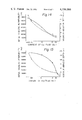
- change in initial magnetic permeability ⁇ o (on the ordinate) is shown relative to change in total content in % by weight of the easily oxidizable element or elements (on the abscissa). Values are given in logarithm scale.
- FIG. 13 shows like change in maximum abrasion depth in ⁇ m. Increase in content of the easily oxidizable element or elements clearly fortifies product against abrasion.
Landscapes
- Engineering & Computer Science (AREA)
- Manufacturing & Machinery (AREA)
- Power Engineering (AREA)
- Soft Magnetic Materials (AREA)
- Powder Metallurgy (AREA)
- Hard Magnetic Materials (AREA)
Abstract
In manufacturing of lamina used for components for magnetic heads such as head cores and shield casings, powder metallurgy is applied to powder material of a permalloy alloy composition in combination with later-staged rolling. Addition of at least one easily oxidizable element is preferably combined with formation of the material powder by means of atomization, more preferably followed by annealing within a reducing atmosphere. Measured formation of oxidized shells on powder particles assists uniform and smooth dispersion of smashed shell flakes into the lamina, thereby greatly raising abrasion resistance of the product without lowering the magnetic properties.
Description
The present invention relates to a method for manufacturing components for magnetic heads, and more particularly relates to improvements in the method for manufacturing components such as a core and a shield casing for magnetic heads used for magnetic sound or video recording and reproducing.
The material used for the above-described components is in general required to have, in addition to high magnetic properties, high mechanical properties, in particular high abrasion resistance since they are usually subjected to hard and frequent frictional contact with running magnetic tapes.
Permalloy alloys are conventionally and generally used for such components but unable to sufficiently suffice such requirement for high abrasion resistance, thereby causing relatively low durability of these components for magnetic heads. It is proposed to add a particular element or elements to permalloy alloys. Such addition, however, is still unable to raise abrasion resistance of the component to an appreciable extent, and liable to lower magnetic characteristics of the product. It is proposed also to add a hard material or materials such as metal oxide to permalloy alloy. This addition, however, is accompanied with difficulty in uniform dispersion of the added material into the base alloy even in molten state. Biased presence of the added material in the base alloy naturally causes biased mechanical and/or magnetic properties of the product.
In view of the above-described state of the art, the inventors of the present invention has tried to greatly raise abrasion resistance of the components used for magnetic heads by improving their manufacturing method.
In conventional manufacturing of a laminated head core, for example, a cast block is reformed into laminae by rolling. Basically, the present invention proposes to introduce the art of powder metallurgy into the above-described manufacturing in order to obtain permalloy alloy blocks to be subsequently subjected to rolling. It is admitted that mere manufacturing of permalloy alloy block by powder metallurgy itself is an established art well known to public. However, permalloy alloy blocks manufactured by powder metallurgy only have very poor abrasion resistance. Further, presence of numerous fine air voids in the block disables easy application of fine cutting to the block and deteriorates magnetic properties of the product.
It is the basic object of the present invention to provide a method for manufacturing components for magnetic heads which have, in addition to high magnetic properties, sufficient mechanical properties, in particular high abrasion resistance.
In accordance with the basic aspect of the present invention, material powder is blended so as to substantially have a permalloy alloy composition, the blended material powder is subjected to compaction to obtain a compressed block, and the compressed block is subjected to rolling after application of sintering.
In more detail, blending of the material powder is carried out by mixing Fe powder with Ni powder. As a substitute, Fe-Ni alloy powder may be used as the base material with addition of a proper material or materials for improving any property of the product.
So-called 78 permalloy may be used for the permalloy alloy in the present invention. 78-permalloy includes, as the base material, a mixture of 60 to 90% by weight of Ni with 5 to 20% by weight of Fe. In addition to the base material, it may include, depending on requirement in use of the product, at least one of 0.5 to 14% by weight of Mo, 0.1 to 20% by weight of Cu, 0.1 to 10% by weight of Cr, 0.1 to 15% by weight of Nb, 0.1 to 10% by weight of Ti, 0.1 to 8% by weight of V, 0.1 to 8% by weight of Si, 0.01 to 5% by weight of Al, 0.1 to 8% by weight of W, 0.1 to 15% by weight of Ta, 0.01 to 15% by weight of Mn, 0.1 to 5 % by weight of Co, 0.005 to 5% by weight of Y, 0.005 to 5% by weight of Ce, 0.005 to 5% by weight of La and 0.005 to 5% by weight of Sm.
So-called 45-permalloy may be usable also, which includes, as the base material, a mixture of 35 to 55% by weight of Ni, with 35 to 55% by weight of Fe, and, as the additive, at least one of the above-described materials.
After complete blending, the material powder is placed, for example, in a rubber casing for compaction by, for example, hydrostatic compaction. When hydrostatic compaction is employed, the compaction pressure should preferably be in a range from 4,000 to 20,000 kg/cm2 and the compaction time in a range from 2 to 300 sec.
The compressed block obtained by the compaction is then subjected to high temperature sintering within a vacuum, reducing gas or inert gas atmosphere.
In the case of sintering within a vacuum atmosphere, the degree of vacuum should preferably be 10-2 Torr or lower. Any degree of vacuum above limit tends to cause oxidation of the material powder, thereby deteriorating magnetic properties of the product.
In the case of sintering within a reducing or inert gas atmosphere, the dew point of the gas should preferably be -20° C. or lower. Any dew point exceeding this value may also cause oxidation of the material powder, thereby lowering magnetic properties of the product.
The sintering temperature should preferably be in a range from 900° to 1,430° C. No effective sintering starts at a temperature below 900° C. whereas any temperature above 1.430° C. may cause melting of the material powder.
The sintering time should preferably be in a range from 1 to 20 hours. No sufficient sintering effect is obtained when heating lasts shorter than 1 hour whereas no remarkable rise in sintering effect is expected when heating time exceeds 20 hours.
Finally, the sintered block is rolled into a lamina of, for example, about 0.3 mm thickness. This rolling preferably includes alternate application of 30 to 70% of cold rollings and annealings at 750° to 850° C.
The lamina so obtained is then cut into laminae of a prescribed pattern. In the case of a laminated head core, such laminae are superposed upon each other and bonded together by suitable resin. In the case of a shield casing, the lamina is subjected to pressure shaping.
In the case of the method of the basic aspect of the present invention, permalloy powder metallurgy is used in combination with the later-staged rolling, thereby successfully raising abrasion resistance of the product. This success accrues from the fact that application of the rolling smashes hard oxidized shells formed on powder particles during the initial blending, compaction and sintering and the smashed pieces disperse uniformly into the body of the rolled lamina.
That is, the first aspect of the present invention tactfully makes use of formation of oxidized shells on powder particles during processes preceding the final rolling. It has been confirmed, however, by the inventors of the present invention, that one cannot always expect sufficient and constant formation of such oxidized shells during manufacturing of the sintered blocks. Consequently, the method of the basic aspect of the present invention cannot always assure successful provision of sufficiently high abrasion resistance.
It is another object of the present invention to enable constant manufacturing of permalloy components for magnetic heads with sufficiently high abrasion resistance.
In accordance with another aspect of the present invention, an easily oxidizable element or elements are added to the base material for permalloy alloy, i.e. mixture of Fe with Ni, and preparation of the material powder includes atomization. Like the method of the basic aspect, the blended material powder is then subjected to compaction, sintering and rolling.
In more detail, the above-described easily oxidizable element or elements are chosen from a group consisting of Al, Ti, Mg, Ca, Ce and Be. The base material of permalloy alloy composition and the easily oxidizable element or elements are blended together by atomization in order to cause formation of oxidized shells on the powder particles. In particular, it was confirmed that remarkable effect can be obtained when Al, Ti, Mg and/or Ca is added to the base material.
The preferable contents for the above-described easily oxidizable elements are as follows;
Al: 0.005 to 2% by weight
Ti: 0.005 to 1.5% by weight
Mg: 0.01 to 2% by weight
Ca: 0.01 to 2% by weight
Ce: 0.005 to 1.0% by weight
Be: 0.001 to 1.0% by weight
When the content of an added element falls short of its lower limit, no sufficient rise in abrasion resistance of the resultant product can be expected. The content of an added element exceeding its upper limit tends to lower magnetic properties of the product obtained. When two or more easily oxidizable elements are used in combination, the total content of such elements should preferably be in a range from 0.005 to 2.0% by weight.
In addition to the above-described easily oxidizable elements, the material powder may contain elements listed in connection with the basic aspect of the present invention.
It is necessary in this aspect of the present invention that at least the material powder containing the easily oxidizable element or elements is prepared by atomization. That is, when only alloy powder having the ultimate composition is used as the base material powder, the molten alloy has to be powdered by atomization. When a part of the ultimate composition is used as the master alloy containing the easily oxidizable element or elements and each remnant is added individually, at least the master alloy has to be powdered by atomization. Further, when any single easily oxidizable element is added, at least the element has to be powdered by atomization.
The atomization used for the present invention may take the form of hydro-atomization in which a substance in molten state is powdered by jet flow of water. It may further take the form of gas-atomization in which a substance in molten state is powdered by flow of compressed gas such as air. A great deal of oxidized shells are formed on the powder particles by use of atomization in blending of the material powder containing easily oxidizable element or elements.
During the last staged rolling, the shells on the powder particles are smashed into fine pieces which then disperse uniformly into the body of the rolled lamina. Concurrently, fine air voids in the sintered block disappear. Such a combined effect greatly raises abrasion resistance of the product.
In the case of the above-described aspect of the present invention, at least one easily oxidizable element is added to the material powder and atomization is used for preparation of the material powder. Use of atomization, however, has its merits with demerits. That is, presence of the oxidized shells on powder particles blocks smooth dispersion of the powder particles and lowers inter-particle bonding. Low inter-particle bond may cause separation of particles from the product depending on the strength of the frictional contact, thereby deteriorating abrasion resistance of the product.
It is the other object of the present invention to provide a method for fortifying the inter-particle bond of the product whilst allowing formation of the oxidized shells on powder particles in preparation of the material powder for components used for magnetic heads.
Thus, in accordance with the other aspect of the present invention, the material powder including at least one easily oxidizable element is subjected to annealing within a reducing atmosphere after preparation including atomization. By this annealing, oxides of easily reducible elements such as Fe and Ni contained in the material powder are reduced in advance of the compaction, sintering and rolling,
The above-described reducing atmosphere should preferably be either hydrogen reducing atmosphere having a dew point of -30° C. or lower or vacuum atmosphere of 10-2 Torr or higher. The annealing temperature should preferably be in a range from 200° to 800° C. The annealing time should preferably be in a range from 0.5 to 20 hours.
No sufficient reduction is obtained when annealing is carried out within a hydrogen reducing atmosphere having a dew point higher than -30° C. or a vacuum atmosphere lower than 10-2 Torr. No reduction starts at any temperature lower than 200° C. whereas sintering starts during annealing when the temperature exceeds 800° C. No sufficient reduction can be completed within 0.5 hours whereas no further development in reduction can be expected even when annealing lasts longer than 20 hours.
Due to such reduction during annealing, oxides formed on the powder particles by atomization are partly reduced. That is, among the oxides in the oxidized shells, those originated from easily oxidizable elements such as Al remain almost unchanged during the annealing. In contrast to this, those originated from easily reducible elements such as Ni and Fe are reduced to their original elements during the annealing.
During the sintering to be carried out after the compaction of the material powder, presence of the reduced elements such as Ni and Fe on the powder particles enables smooth inter-particle dispersion, thereby producing sintered blocks with high inter-particle bond.
Such a high inter-particle bond well prevents undesirable fall of particles from the products which is otherwise caused by frictional contact with running tapes.
The invention will hereinafter be explained in more detail in reference to the accompanying drawings, in which
FIG. 1 is a top view of a magnetic head core test piece used for measurement of abrasion resistance in the following examples of the present invention.
FIG. 2 is a side view of the above-described test piece,
FIG. 3 is a side sectional view of the tape contacting face of the sample No. 1 (present invention) in Example 1,
FIG. 4 is a side sectional view of the tape contacting face of the sample No. 9 (conventional) in Example 2, and
FIG. 5 is a perspective view of the shield casing test pieces used in Example 5, and
FIGS. 6 through 17 are graphs for showing results obtained in Examples 9 and 10.
The following examples are illustrative of the present invention but not to be construed as limiting the same.
Following powders were selectively used for preparation of the material powder;
Fe--Carbonyl iron powder
Ni--Carbonyl nickel powder
Mo--Molybdenum powder
Cu--Electrolytic copper powder
Cr--Electrolytic chromium powder
Nb--Nickel-niobium alloy powder
Ti--Titanium halide powder
V--Ferro-vanadium alloy powder
Si--Ferro-silicon alloy powder
Al--Ferror-alluminum alloy powder
W--Ferro-tungsten alloy powder
Ta--Nickel-tantalum alloy powder
Mn--Ferro-manganese alloy powder
Co--Electrolytic cobalt powder
Using these powders, eight material powder samples No. 1 to No. 8 of different compositions were prepared as shown in Table 1.
              TABLE 1
______________________________________
Sample No    Composition (in % by weight)
INVEN- CONVEN-
TION   TIONAL    Ni     Fe   Mo   Cu  Nb  Ti  Si  Cr
______________________________________
1 (17)  9        79.0   16.5 4.5
2 (18) 10        78.5   13.0 4.0  5.0
3 (19) 11        81.5   10.0 1.5      7.0
4 (20) 12        83.0   12.0          3.0 2.0
5 (21) 13        84.0   11.8                  4.2
6 (22) 14        50.0   50.0
7 (23) 15        45.0   53.0 2.0
8 (24) 16        39.0   51.0                      10.0
______________________________________
Each material powder sample was mixed from 0.5 to 4 hours within a V-type mixer and placed within a rubber container for hydrostatic compaction at 15.000 kg/cm2 for about 200 sec. A compressed block of 50×50×100 mm. was obtained. The compressed block was then sintered at 1,300° C. for about 15 hours within a vacuum atmosphere of 10-2 Torr. or lower. The sintered block was subjected to alternate application of cold rolling of 50% and interim annealing at 800° C. for 2 hours until a lamina of 0.3 mm was obtained.
An O-ring shaped test piece was stamped out of the permalloy alloy lamina. The outer diameter was 10 mm, and the innner diameter was 6 mm. The test piece was subjected to annealing at 1,100° C. for 2 hours within a hydrogen atmosphere. Magnetic properties and hardness of the resultant test piece were measured.
Separately, a number of pieces of the pattern shown in FIG. 1 were stamped out of the above-described permalloy alloy lamina, the pattern being to the transverse cross sectional profile of an ordinary magnetic head core. 25 sheets of pieces were superposed and bonded together by means of suitable resin in order to obtain a magnetic head core test piece such as shown in FIG. 2. The dimension of this test piece was as follows;
______________________________________
Length                1 = 11.5 mm.
Width                 w = 10 mm.
Radius of curvature of
the tape contacting face A
                      R = 10 mm.
Thickness             d = 7 mm.
______________________________________
In the abrasion test, the test piece was mounted to an auto-reverse type cassette deck and a gamma hematite tape was used, which is generally known to cause maximum abrasion. Running of the tape was continued for 100 hours and the maximum value Dmax of the abrasion depth D in the tape contacting face A of the test piece was measued. The abrasion test was carried out in an atmosphere of 20°±2° C. temperature and 40 to 50% humidity. The results of the measurements are shown in Table 2. Abrasion in the tape contacting face A of the test piece No. 1 is shown in FIG. 3.
                                  TABLE 2
__________________________________________________________________________
Magnetic properties
    Initial     Saturated  Maximum
    magnetic
          Coercive
                magnetic flux
                       Hard-
                           abrasion
Sample
    permeabi-
          force density B.sub.10
                       ness
                           depth D.sub.max
NO. lity (μ.sub.o)
          Hc (A/m)
                (T)    (Hv)
                           (μm)
                                  category
__________________________________________________________________________
1   70,000
          1.2   0.76   156 1.2    present
2   80,000
          1.6   0.70   132 1.9    invention
3   100,000
          0.8   0.60   205 0.2
4   50,000
          2.0   0.57   220 0.2
5   45,000
          2.0   0.55   220 0.35
6   2,500 8     1.40   130 0.8
7   5,000 6.0   1.35   140 0.4
8   2,500 6.8   0.55   130 0.3
9   90,000
          0.88  0.76   140 13     conventional
10  70,000
          1.44  0.71   115 20
11  120,000
          0.64  0.61   192 3
12  60,000
          1.6   0.58   210 2.5
13  40,000
          2.48  0.53   208 4.5
14  2,000 8     1.40   110 12
15  5,000 6.4   1.35   120 9
16  3,000 6.4   0.55   115 6
__________________________________________________________________________
Permalloy alloy powder prepared by carbonyl process was used as the base material while including 75% by weight of Ni and remaining amount of Fe. Carbonyl iron powder and carbonyl nickel powder were added to this base material. Further materials were added in order to obtain eight material powder samples No. 17 to 24 as shown in Table 1. Each material powder sample was subjected to compaction, sintering and rolling in order to obtain a permalloy lamina under conditions same as those employed in Example 1. The test piece so obtained were subjected to measurements of magnetic properties, hardness and abrasion resistance. Results are shown in Table 3.
For comparison, permalloy alloy blocks were prepared in accordance with the conventional casting process and were formed into permalloy alloy laminae in a manner the same as preparation of the laminae in accordance with the present invention. Similar measurements were applied to samples No. 9 to No. 16 and the condition of the tape contacting face of the sample No. 9 after abrasion test is shown in FIG. 4. The compositions of the conventional samples No. 9 to 16 are equal to those of the samples No. 1 to 8 in accordance with the present invention.
                                  TABLE 3
__________________________________________________________________________
Magnetic properties
    Initial     Saturated  Maximum
    magnetic
          Coercive
                magnetic flux
                       Hard-
                           abrasion
Sample
    permeabi-
          force density B.sub.10
                       ness
                           depth D.sub.max
NO. lity (μ.sub.o)
          Hc (A/m)
                (T)    (Hv)
                           (μm)
                                  Category
__________________________________________________________________________
17  80,000
          0.8   0.74   156 1.3    Present
18  80,000
          1.2   0.70   140 1.7    invention
19  120,000
          0.8   0.59   210 0.1
20  50,000
          2.0   0.57   200 0.2
21  30,000
          3.2   0.51   230 0.25
22  2,000 9.6   1.35   140 0.9
23  4,000 7.2   1.28   150 0.4
24  2,000 8     0.53   130 0.4
__________________________________________________________________________
The results given in Table 2 clearly indicate that employment of the present invention in manufacturing of magnetic head cores results in surprising rise in abrasion resistance. Under same condition of abrasion, the maximum abrasion depth for the samples of the present invention is one-tenth or smaller than that for the samples of the conventional art. Even in the case of sample No. 6 which contains no additional component for improvement of properties, its abrasion resistance is by far higher than the conventional samples containing such an additional component or components. No particular lowering in magnetic properties is recognized. High abrasion resistance could be obtained either when Ni and Fe metallic powders were used (Example 1) or when Ni-Fe alloy powder was used (Example 2).
The above-described improvement in abrasion resistance is believed to accrue from the fact that surfaces of powder particles are a bit oxidized to form shells during compaction and sintering, and the oxidized shells are smashed into fine pieces during rolling of the sintered block which are uniformly dispersed into the body of the lamina and contributes to improvement in abrasion resistance. Due to this internal dispersion, the fine pieces of metal oxides are not reduced during annealing within a hydrogen atmosphere to be applied after stamping of the lamina.
Each of the alloys having the compositions shown in Table 4 was molten by means of vacuum melting process and powdered by means of hydro-atomization within a mixture of air with argon gass.
              TABLE 4
______________________________________
Sample
      Composition (in % by weight)
NO.   Ni    Fe    Mo   Cu   Al   Ti   Mg   Ca   Ce  Be
______________________________________
25    78    13    4.0  4.5  0.5
26    78    13    3.5  4.0  1.5
27    78    13    4.0  4.9       0.1
28    78    13    3.0  4.0       2.0
29    78    13    4.0  4.9            0.1
30    78    13    3.0  4.0            2.0
31    78    13    4.0  4.9                 0.01
32    78    13    3.0  4.0                 2.0
33    78    13    4.0  4.9                      0.1
34    78    13    3.0  4.0                      1.0
35    78    13    4.0  5.0                          0.001
36    78    13    4.0  4.0                          1.0
37    78    13    4.0  4.97 0.05 0.02
38    78    13    4.0  4.899     0.05      0.05     0.001
39    78    13    4.0  4.97 0.02      0.05
40    45    53    2.0
41    45    53    1.98      0.02
42    45    52    2.0       1.0
43    45    53    1.98           0.02
44    45    52    2.0            1.0
______________________________________
Each material powder was then placed within a rubber casing for hydrostatic compaction at about 15,000 kg/cm2 for about 200 sec, thereby obtaining a compressed block of 50×50×100 mm. The compressed block was subjected to sintering at 1,300° C. for 5 hours within a vacuum atmosphere and the sintered block was subjected to alternate application of cold rolling of 50% and interim annealing at 800° C. for 2 hours until a permalloy alloy lumina of 0.3 mm thickness is obtained.
Test pieces and magnetic head core samples were prepared and measurements were carried out as in Example 1. The results of the measurements are given in Table 5.
              TABLE 5
______________________________________
Magnetic properties
      Initial magnetic
                  Coercive  Saturated
Sample
      permeability
                  force     magnetic flux
                                      Abrasion
NO.   μ.sub.o  Hc (A/m)  density B.sub.10 (T)
                                      μ m
______________________________________
25    15,000      1.84      0.61      11
26    11,000      2.08      0.55      9
27    38,000      1.92      0.56      12
28    10,000      3.12      0.48      7.2
29    54,000      2.00      0.68      10
30     8,000      3.28      0.56      7.1
31    42,000      0.96      0.71      21
32     6,000      3.04      0.61      5.6
33    18,000      3.2       0.60      13
34     6,000      4.0       0.50      5.5
35    38,000      1.92      0.59      12
36    10,000      4.0       0.53      7.2
37    43,000      1.76      0.69      9.3
38    32,000      1.92      0.69      8.6
39    21,000      1.44      0.69      10.3
40     4,000      8.8       13.3      4.1
41     2,500      12        13.3      3.5
42     1,200      14.4      13.0      2.8
43     3,000      12        13.0      4.0
44     1,800      16        12.6      3.9
______________________________________
For comparison, material powder samples No. 45 to 64 having compositions same as those of samples No. 25 to 44, respectively in the listed order, were formed into permalloy alloy cast blocks by means of conventional vacuum melting process. Each cast block was rolled into a permalloy alloy lamina of 0.3 mm thickness which was then subjected to tests similar to those applied to samples No. 25 to 44. The results are given in Table 6.
The extent of oxidization by the above-described atomization applied to samples No. 25 to 44 was from 200 to 3,000 ppm. for each.
              TABLE 6
______________________________________
Magnetic properties
                  Coercive  Saturated
Sample
      Initial magnetic
                  force     magnetic flux
                                      Abrasion
NO.   permeability
                  Hc (A/m)  density B.sub.10 (T)
                                      μ m
______________________________________
45    20,000      1.6       0.62      69
46    15,000      2.4       0.58      63
47    41,000      1.44      0.56      71
48    13,000      2.8       0.49      32
49    70,000      1.6       0.68      65
50    14,000      3.04      0.59      41
51    85,000      0.72      0.72      85
52    13,000      2.64      0.64      55
53    21,000      2.8       0.62      73
54    12,000      3.6       0.52      42
55    51,000      1.68      0.61      81
56    12,000      3.52      0.54      62
57    52,000      0.96      0.70      72
58    55,000      0.88      0.69      71
59    61,000      0.9       0.71      82
60     5,000      8.0       1.35      43
61     3,000      9.6       1.33      41
62     1,500      12        1.30      35
63     4,000      10.4      1.33      46
64     2,100      14.4      1.28      32
______________________________________
The results given in Tables 5 and 6 clearly indicate that addition of an easily oxidizable element or elements in combination with preparation of the material powder by means of atomization greatly improves abrasion resistance of the product.
Each of the nine material powder samples No. 65 to 73 having compositions shown in Table 7 was molten by vacuum melting process and powdered by means of hydro-atomization within a mixture of air with argon gass.
              TABLE 7
______________________________________
Sample
      Composition (in % by weight)
NO.   Ni     Fe     Mo   Cu   Al   Ti   Mg   Ca   Be
______________________________________
65    78     13     4    4.5  0.5
66    78     13     4    4.9       0.1
67    78     13     3.0  4.0       2.0
68    78     13     4    4.9                 0.01
69    78     13     3.0  4.0                 2.0
70    78     13     4    5.0                      0.001
71    78     13     4    4.889     0.05      0.05 0.001
72    78     13     4    4.97 0.02      0.05
73    45     52     2.0            1.0
______________________________________
Each material powder was then subjected to reduction at 400° C. for 10 hours within a hydrogen atmosphere of -70° C. dew point. Ring shaped test piece and a head core sample was prepared in a manner similar to that in Example 1. Measurements of various properties were also carried out just like in Example 1. The obtained results are given in Table 8.
The amounts of oxygen possessed by each atomized material powder before and after the reduction were measured and the results are given in Table 10.
              TABLE 8
______________________________________
Magnetic properties
                  Coercive  Saturated
Sample
      Initial magnetic
                  force     magnetic flux
                                      Abrasion
NO.   permeability
                  Hc (A/m)  density B.sub.10 (T)
                                      μm
______________________________________
65    20,000      1.20      0.60      13
66    40,000      1.60      0.56      16
67    13,500      2.88      0.48      8.0
68    61,000      0.80      0.72      23
69    11,000      2.80      0.63      6.2
70    48,000      1.76      0.59      14
71    50,000      1.12      0.69      9.4
72    46,000      1.08      0.70      12.6
73     2,100      14.4      1.26      4.0
______________________________________
For comparison, material powder samples No. 74 to 82 having compositions same as those of samples 65 to 74, respectively in the listed order, were formed into permalloy alloy cast blocks by means of conventional vacuum melting process.
Each cast was rolled into a permalloy alloy lamina of 0.3 mm thickness which was then subjected to tests similar to those applied to samples No. 65 to 73. The results are give in Table 9.
              TABLE 9
______________________________________
magnetic properties
      Initial magnetic
                  Coercive  Saturated
Sample
      permeability
                  force     magnetic flux
                                      Abrasion
NO.   μ.sub.o  Hc (A/m)  density B.sub.10 (T)
                                      μm
______________________________________
74    20,000      1.60      0.62      69
75    41,000      1.44      0.56      71
76    13,000      2.8       0.49      32
77    85,000      0.72      0.72      85
78    13,000      2.64      0.64      55
79    51,000      1.68      0.61      81
80    55,000      0.88      0.69      71
81    61,000      0.9       0.71      82
82     2,100      14.4      1.28      32
______________________________________
              TABLE 10
______________________________________
       Amount of oxygen in ppm.
Sample   After atomization
NO.      (before reduction)
                         After reduction
______________________________________
65       2,100           600
66       1,600           400
67       2,600           480
68       800             300
69       3,000           800
70       860             260
71       1,100           340
72       1,200           410
73       2,100           1,00
______________________________________
The results given in Tables 8 and 9 clearly indicate that introduction of the annealing within a reducing atmosphere into preparation of the material powders greatly contributes to improvement in abrasion resistance of the products. Further, the results given in Table 10 indicate remarkable decrease in content of oxygen which resulted from annealing in a reducing atmosphere.
Permalloy alloy laminae were prepared in a manner same as that in Example 1 while using the material powder samples No. 1 to 8. Ring-shaped test pieces were stamped out of the laminae. Likewise shield casing test pieces such as shown in FIG. 5 were formed of the laminae. They were all subjected to tests and measurements substantially similar to those employed in Example 1. The results are given in Table 11.
              TABLE 11
______________________________________
Sample     Maximum abrasion
NO.        depth D.sub.max in μm
                         Category
______________________________________
1          1.1           Present
2          1.8           invention
3          0.2
4          0.2
5          0.4
6          0.8
7          0.3
8          0.3
9          14            Conventional
10         19
11         3
12         3
13         5
14         11
15         10
16         6
______________________________________
For comparison, like shield casing test pieces were prepared using the material powder samples No. 9 to 16 in Example 1 by means of the conventional melt casting process and subjected to similar tests and measurements. The results obtained are given in Table 11, also.
Like shield casing test pieces were prepared in a manner same as that in Example 2 while using the material powder samples No. 17 to 24. Test pieces were all subjected to tests and measurements substantially similar to those employed in Example 5. The results obtained are given in Table 12.
              TABLE 12
______________________________________
             Maximum
             abrasion
       Sample
             depth D.sub.max in
       No.   μm
______________________________________
       17    1.2
       18    1.7
       19    0.1
       20    0.2
       21    0.2
       22    1.0
       23    0.5
       24    0.4
______________________________________
The results given in the Tables clearly indicate advantages accruing from the present invention.
Like shield casing test pieces were prepared in a manner same as that in Example 3 while using the material powder samples No. 25 to 44 (see Table 4). Test pieces were all subjected to tests and measurements substantially similar to those employed in Example 5. The results obtained are given in Table 13.
For comparison, like shield casing test pieces were prepared by means of the conventional process described in Example 3 whilst using the material powder samples having compositions same as those of samples No. 25 to 44. The results of the tests and measurements are given in Table 13.
              TABLE 13
______________________________________
            maximum abrasion depth
Sample      D.sub.max in μm
NO.         Present invention
                         Conventional
______________________________________
25          12           71
26          9            64
27          12           73
28          8            32
29          11           64
30          7            42
31          20           87
32          5.2          57
33          12           72
34          5.2          41
35          13           82
36          7.4          64
37          9.1          72
38          8.8          72
39          11           84
40          4.2          43
41          3.7          40
42          2.8          36
43          4.2          46
44          3.8          33
______________________________________
It is clearly noted from the results given in Table 13 that employment of the present invention greatly improves abrasion resistance of the products.
Like shield casing test pieces were prepared in a manner same as that in Example 4 whilst using the material powder samples No. 65 to 74 (see Table 7). Test pieces were all subjected to tests and measurements substantially similar to those employed in Example 5. The results obtained are given in Table 14.
For comparison, like shield casing test pieces were prepared by means of the conventional process described in Example 4 while using the material powder samples having compositions same as those of samples 65 to 73. The results of the tests and measurements are given in Table 14.
              TABLE 14
______________________________________
            Maximum abrasion depth
Sample      D.sub.max in μm
NO.         Present invention
                         Conventional
______________________________________
65          12           71
66          15           73
67          8.0          32
68          22           87
69          6.3          57
70          13           82
71          9.2          72
72          12.2         84
73          4.1          33
______________________________________
The results given in Table 14 clearly indicates advantage of the present invention over the conventional method.
Material powder sample No. 83 to 101 having the compositions shown in Table 15 were used while preparation of test pieces and measurement of their properties were carried out just as in Example 3. The results obtained are shown in Table 16 and FIGS. 6 through 11.
In FIG. 6, change in initial magnetic permeability μo (on the ordinate) is shown relative to change in total content in % by weight of the easily oxidizable element or elements (on the abscissa). Values are given in logarithm scale.
              TABLE 15
______________________________________
Sam-
ple  Content (% by weight)
No.  Ni    Fe     Mo   Cu   Al   Ti   Mg   Ca   Ce   Be
______________________________________
83   78    13     4.0  4.995
                            0.005
84   78    13     4.0  4.99 0.01
85   78    13     4.0  4.9  0.1
86   78    13     4.0  4.995     0.005
87   78    13     4.0  4.99      0.01
88   78    13     3.5  4.0       1.5
89   78    13     4.0  4.99           0.01
90   78    12.5   3.0  4.0            2.5
91   78    13     4.0  4.993               0.007
92   78    13     4.0  4.9                 0.1
93   78    12.0   3.0  4.0                 3.0
94   78    13     4.0  4.995
                            0.002
                                 0.003
95   78    13     4.0  4.995
                            0.003     0.002
96   78    13     4.0  4.99 0.005
                                 0.005
97   78    13     4.0  4.99 0.005     0.005
98   78    13     4.0  4.95 0.025               0.025
99   78    13     4.0  4.95      0.025     0.025
100  78    13     3.0  4.0  0.5  0.5  0.5  0.5
101  78    13     3.0  4.0       0.5  0.5  0.5  0.5
______________________________________
              TABLE 16
______________________________________
                           Saturated
                                    maximum
       Initial mag-
                  Coercive magnetic flux
                                    abrasion
Sample netic permea-
                  force Hc density B.sub.10
                                    depth D.sub.max
No.    bility (μ.sub. o)
                  (A/m)    (T)      (μm)
______________________________________
83     57,500     0.88     0.70     27.2
84     44,500     1.02     0.66     22.3
85     23,000     1.44     0.63     15.0
86     72,000     1.00     0.70     26.2
87     70,000     1.02     0.62     20.2
88     10,000     2.22     0.54     7.2
89     65,500     1.20     0.70     21.3
90      6,500     3.55     0.54     7.0
91     52,000     0.81     0.72     25.1
92     19,000     2.20     0.65     11.3
93      5,000     4.10     0.58     5.3
94     120,000    0.80     0.72     24.0
95     77,000     0.82     0.70     19.8
96     98,000     0.82     0.69     16.5
97     64,000     0.92     0.69     14.0
98     15,500     2.30     0.60     5.8
99     13,000     2.20     0.62     5.0
100    11,000     2.56     0.61     4.0
101     8,000     3.11     0.59     3.0
______________________________________
FIG. 7 shows like change in maximum abrasion depth in μm. Increase in content of the easily oxidizable element or elements clearly contributes to fortification of the products.
Changes in initial magnetic permeability (solid curve) and maximum abrasion depth (dotted curve) are shown in FIG. 8 with respect to change in content of Ca. Like changes are shown in FIGS. 9, 10 and 11 for Mg, Ti and Al, respectively.
The material powder samples No. 83 to 86, 92 and 93 used in Example 9 and material samples No. 102 to 114 having the compositions shown in Table 17 were used while preparation of test pieces and measurement of their properties were carried out just as in Example 4. The results obtained are shown in Table 18 and FIGS. 12 to 17, respectively.
              TABLE 17
______________________________________
Sample
      Content (% by weight)
No.   Ni    Fe    Mo   Cu   Al   Ti   Mg   Ca   Ce  Be
______________________________________
102   78    13    3.0  4.0  2.0
103   78    13    4.0  4.98      0.02
104   78    13    4.0  4.5       0.5
105   78    13    4.0  4.995               0.05
106   78    13    4.0  4.0                 1.0
107   78    13    4.0  4.99           0.01
108   78    13    4.0  4.9            0.10
109   78    13    4.0  4.0            1.0
110   78    13    3.0  4.0            2.0
111   78    13    4.0  4.994
                            0.003
                                 0.003
112   78    13    4.0  4.98 0.005
                                 0.005
                                      0.005
                                           0.005
113   78    13    4.0  4.0  0.5  0.2  0.5           0.3
114   78    13    3.0  4.0  1.0  0.5  1.0  0.5
______________________________________
              TABLE 18
______________________________________
                           Saturated
                                    maximum
       Initial mag-
                  Coercive magnetic flux
                                    abrasion
Sample netic permea-
                  force Hc density B.sub.10
                                    depth D.sub.max
No.    bility (μ.sub. o)
                  (A/m)    (T)      (μm)
______________________________________
83     65,000     0.92     0.70     27.3
84     58,000     0.92     0.70     21.5
85     31,500     1.10     0.62     13.4
86     70,000     0.82     0.72     25.3
92     40,000     1.12     0.68     12.7
93      7,500     3.20     0.60     4.0
102    12,500     1.51     0.60     10.0
103    67,500     1.20     0.70     21.8
104    32,500     2.20     0.54     9.0
105    67,000     0.80     0.72     30.0
106    16,000     2.10     0.65     8.1
107    70,000     0.81     0.70     20.5
108    65,000     0.92     0.68     9.5
109    42,000     1.21     0.65     5.5
110    18,000     2.10     0.61     5.0
111    100,000    0.76     0.71     22.3
112    75,000     0.85     0.70     15.0
113     8,000     2.25     0.65     6.5
114     6,000     2.41     0.58     3.0
______________________________________
In FIG. 12, change in initial magnetic permeability μo (on the ordinate) is shown relative to change in total content in % by weight of the easily oxidizable element or elements (on the abscissa). Values are given in logarithm scale.
FIG. 13 shows like change in maximum abrasion depth in μm. Increase in content of the easily oxidizable element or elements clearly fortifies product against abrasion.
Changes in initial magnetic permeability (solid curve) and maximum abrasion depth (dotted curve) are shown in FIG. 14 with respect to change in content of Ca. Like changes are shown in FIGS. 15, 16 and 17 for Mg, Ti and Al, respectively.
Claims (20)
1. A method for manufacturing components for magnetic heads comprising
preparing powder material of a permalloy alloy composition,
compacting said powder material into a compressed block,
sintering said compressed block at a temperature of at least 900° C. for at least one hour within a vacuum, hydrogen or inert atmosphere to form a sintered block,
rolling said sintered block into a lamina, and forming said components from said lamina, thereby substantially raising abrasion resistance without lowering magnetic properties of said components.
2. A method as claimed in claim 1 in which said preparing includes
adding to a base material of a permalloy alloy composition at least one element chosen from a group consisting of 0.5 to 14.0% by weight of Mo, 0.1 to 20% by weight of Cu, 0.1 to 10% by weight of Cr, 0.1 to 15% by weight of Nb, 0.1 to 10% by weight of Ti, 0.1 to 8.0% by weight of V, 0.1 to 8% by weight of Si, 0.01 to 5% by weight of Al, 0.1 to 8% by weight of W, 0.1 to 15% by weight of Ta, 0.01 to 15% by weight of Mn, 0.1 to 5% by weight of Co, 0.005 to 5% by weight of Y, 0.005 to 5% by weight of Ce, 0.005 to 5% by weight of La and 0.005 to 5% by weight of Sm.
3. A method as claimed in claim 1 in which
said compacting is carried out by hydrostatic compaction at a pressure from 4,000 to 20,000 Kg./cm2 for 2 to 300 seconds.
4. A method as claimed in claim 1 in which
said heating is carried out in a vacuum atmosphere.
5. A method as claimed in claim 4 in which
the degree of vacuum is 10-2 Torr. or lower.
6. A method as claimed in claim 1 in which
said heating is carried out within a reducing gas atmosphere.
7. A method as claimed in claim 1 in which
said heating is carried out within an inert gas atmosphere.
8. A method as claimed in claim 6 or 7 in which
the dew point of said gas is -20° C. or lower.
9. A method as claimed in claim 1 in which
said heating is carried out at a temperature in a range from 900° to 1,430° C.
10. A method as claimed in claim 1 in which
said heating is carried out for a period in a range from 1 to 20 hours.
11. A method as claimed in claim 1 in which
said rolling includes alternate application of cold rolling of from 30 to 70% and interim annealing at a temperature in a range from 750° to 850° C.
12. A method as claimed in claim 1 in which said preparing includes
adding to a base material of a permalloy composition at least one easily oxidizable element, and
powdering by means of atomization.
13. A method as claimed in claim 12 in which
said easily oxidizable element is chosen from a group consisting of 0.005 to 2% by weight of Al, 0.005 to 1.5% by weight of Ti, 0.01 to 2% by weight of Mg, 0.01 to 2% by weight of Ca, 0.005 to 1.0% by weight of Ce and 0.001 to 1.0% by weight of Be.
14. A method as claimed in claim 12 in which
said atomization is hydro-atomization.
15. A method as claimed in claim 12 in which
said atomization is gas-atomization.
16. A method as claimed in claim 12 in which said preparing further includes
annealing within a reducing atmosphere said powder material prepared by said atomization.
17. A method as claimed in claim 16 in which
said annealing is carried out within a vacuum atmosphere having a degree of vacuum of 10-2 Torr. or lower.
18. A method as claimed in claim 16 in which said annealing is carried out within a hydrogen atmosphere having a dew point of -30° C. or lower.
19. A method as claimed in claim 17 or 18 in which
said annealing is carried out at a temperature in a range from 200° to 800° C.
20. A method as claimed in claim 17 or 18 in which
said annealing is carried out for a period in a range from 0.5 to 20 hours.
Applications Claiming Priority (8)
| Application Number | Priority Date | Filing Date | Title |
|---|---|---|---|
| JP54-64819 | 1979-05-25 | ||
| JP6481979A JPS55157217A (en) | 1979-05-25 | 1979-05-25 | Manufacture of thin plate for magnetic head core |
| JP54-98317 | 1979-07-31 | ||
| JP54098317A JPS5811482B2 (en) | 1979-07-31 | 1979-07-31 | Manufacturing method of core material for magnetic heads |
| JP9855579A JPS5623713A (en) | 1979-08-01 | 1979-08-01 | Manufacture of thin plate for magnetic head core |
| JP54-98555 | 1979-08-01 | ||
| JP15909279A JPS5683821A (en) | 1979-12-10 | 1979-12-10 | Production of case material for magnetic head |
| JP54-159092 | 1979-12-10 |
Publications (1)
| Publication Number | Publication Date |
|---|---|
| US4336066A true US4336066A (en) | 1982-06-22 |
Family
ID=27464490
Family Applications (1)
| Application Number | Title | Priority Date | Filing Date |
|---|---|---|---|
| US06/152,782 Expired - Lifetime US4336066A (en) | 1979-05-25 | 1980-05-23 | Method for manufacturing components for magnetic heads of increased abrasion resistance |
Country Status (4)
| Country | Link |
|---|---|
| US (1) | US4336066A (en) |
| DE (1) | DE3019449C2 (en) |
| FR (1) | FR2458868A1 (en) |
| GB (1) | GB2051622A (en) |
Cited By (3)
| Publication number | Priority date | Publication date | Assignee | Title |
|---|---|---|---|---|
| US4752344A (en) * | 1986-12-22 | 1988-06-21 | International Business Machines Corporation | Magnetic layer and method of manufacture |
| WO1999067434A1 (en) * | 1998-06-23 | 1999-12-29 | Pes Inc. | Corrosion resistant solenoid valve |
| CN104550984A (en) * | 2014-12-15 | 2015-04-29 | 中国航空工业集团公司北京航空材料研究院 | Preparation method of nickel-based high-temperature alloy powder for 3D (Three Dimensional) printing |
Families Citing this family (1)
| Publication number | Priority date | Publication date | Assignee | Title |
|---|---|---|---|---|
| CN105220017A (en) * | 2015-11-13 | 2016-01-06 | 无锡清杨机械制造有限公司 | A kind of nickel alloy wire and production method thereof |
Citations (6)
| Publication number | Priority date | Publication date | Assignee | Title |
|---|---|---|---|---|
| US3728111A (en) * | 1971-09-21 | 1973-04-17 | Asea Ab | Method of manufacturing billets from powder |
| US3814598A (en) * | 1970-12-29 | 1974-06-04 | Chromalloy American Corp | Wear resistant powder metal magnetic pole piece made from oxide coated fe-al-si powders |
| US4029501A (en) * | 1976-01-26 | 1977-06-14 | Rca Corporation | Method of preparing improved magnetic head material |
| US4029475A (en) * | 1973-12-31 | 1977-06-14 | Kabushiki Kaisha Hamai Seisakusho | Blank for rolling and forging and method of producing same |
| SU576160A1 (en) * | 1974-12-02 | 1977-10-15 | Предприятие П/Я Р-6209 | Method of manufacturing sintered articles from alloys |
| US4209326A (en) * | 1977-06-27 | 1980-06-24 | American Can Company | Method for producing metal powder having rapid sintering characteristics |
Family Cites Families (4)
| Publication number | Priority date | Publication date | Assignee | Title |
|---|---|---|---|---|
| GB1053594A (en) * | 1963-10-21 | |||
| JPS5429446B1 (en) * | 1970-08-10 | 1979-09-22 | ||
| JPS53127707A (en) * | 1977-04-13 | 1978-11-08 | Nippon Gakki Seizo Kk | Production of laminated type head core |
| CA1082862A (en) * | 1977-05-16 | 1980-08-05 | Carpenter Technology Corporation | Powder metallurgy method for making shaped articles and product thereof |
-
1980
- 1980-05-21 DE DE3019449A patent/DE3019449C2/en not_active Expired
- 1980-05-22 GB GB8016976A patent/GB2051622A/en not_active Withdrawn
- 1980-05-23 FR FR8011993A patent/FR2458868A1/en active Granted
- 1980-05-23 US US06/152,782 patent/US4336066A/en not_active Expired - Lifetime
Patent Citations (6)
| Publication number | Priority date | Publication date | Assignee | Title |
|---|---|---|---|---|
| US3814598A (en) * | 1970-12-29 | 1974-06-04 | Chromalloy American Corp | Wear resistant powder metal magnetic pole piece made from oxide coated fe-al-si powders |
| US3728111A (en) * | 1971-09-21 | 1973-04-17 | Asea Ab | Method of manufacturing billets from powder |
| US4029475A (en) * | 1973-12-31 | 1977-06-14 | Kabushiki Kaisha Hamai Seisakusho | Blank for rolling and forging and method of producing same |
| SU576160A1 (en) * | 1974-12-02 | 1977-10-15 | Предприятие П/Я Р-6209 | Method of manufacturing sintered articles from alloys |
| US4029501A (en) * | 1976-01-26 | 1977-06-14 | Rca Corporation | Method of preparing improved magnetic head material |
| US4209326A (en) * | 1977-06-27 | 1980-06-24 | American Can Company | Method for producing metal powder having rapid sintering characteristics |
Cited By (5)
| Publication number | Priority date | Publication date | Assignee | Title |
|---|---|---|---|---|
| US4752344A (en) * | 1986-12-22 | 1988-06-21 | International Business Machines Corporation | Magnetic layer and method of manufacture |
| WO1999067434A1 (en) * | 1998-06-23 | 1999-12-29 | Pes Inc. | Corrosion resistant solenoid valve |
| GB2354258A (en) * | 1998-06-23 | 2001-03-21 | Petroleum Eng Services | Corrosion resistant solenoid valve |
| CN104550984A (en) * | 2014-12-15 | 2015-04-29 | 中国航空工业集团公司北京航空材料研究院 | Preparation method of nickel-based high-temperature alloy powder for 3D (Three Dimensional) printing |
| CN104550984B (en) * | 2014-12-15 | 2016-08-24 | 中国航空工业集团公司北京航空材料研究院 | A kind of preparation method of 3D printing Ni-base Superalloy Powder |
Also Published As
| Publication number | Publication date |
|---|---|
| GB2051622A (en) | 1981-01-21 |
| DE3019449A1 (en) | 1981-04-16 |
| FR2458868B1 (en) | 1985-03-01 |
| DE3019449C2 (en) | 1985-06-13 |
| FR2458868A1 (en) | 1981-01-02 |
Similar Documents
| Publication | Publication Date | Title |
|---|---|---|
| US4079430A (en) | Magnetic head | |
| JP4971886B2 (en) | Soft magnetic powder, soft magnetic molded body, and production method thereof | |
| US5350628A (en) | Magnetic sintered composite material | |
| US8172956B2 (en) | Sintered soft magnetic powder molded body | |
| KR20050051560A (en) | Iron nitride magnetic powder and method of producing the powder | |
| WO2002081129A1 (en) | Composite soft magnetic sintered material having high density and high magnetic permeability and method for preparation thereof | |
| US4336066A (en) | Method for manufacturing components for magnetic heads of increased abrasion resistance | |
| JPS61124038A (en) | Deflection yoke for electromagnetic deflection type cathode ray tube and manufacture thereof | |
| JPH0447017B2 (en) | ||
| JP2002275600A (en) | Raw material powder for sintered soft magnetic stainless steel and method for producing sintered soft magnetic stainless steel using the same | |
| DE68912525T2 (en) | Magnetic material, manufacturing method and magnetic head. | |
| JP2004156102A (en) | Method for producing composite soft magnetic sintered material having high density and high resistance | |
| JP2907899B2 (en) | Method for producing molded article of high magnetic permeability alloy and magnetic head constituted by members of molded article obtained by this method | |
| JPS6211402B2 (en) | ||
| US3972745A (en) | Ni-Fe-Al Material having high magnetic permeability | |
| JPH0138862B2 (en) | ||
| JPS62277703A (en) | Fe-ni alloy dust core | |
| JPH0373612B2 (en) | ||
| JPS61127848A (en) | Manufacture of sintered alnico magnet | |
| JPS6346962B2 (en) | ||
| JPH06342715A (en) | Dust core and its manufacture | |
| US4608228A (en) | Ni-Fe magnetic head including 1.5-2% Ta | |
| JPS6248748B2 (en) | ||
| JPS60152656A (en) | Magnetic material having high performance and its manufacture | |
| JPS6238411B2 (en) |
Legal Events
| Date | Code | Title | Description |
|---|---|---|---|
| STCF | Information on status: patent grant |
Free format text: PATENTED CASE |