US4324113A - Sliding block coupling - Google Patents
Sliding block coupling Download PDFInfo
- Publication number
- US4324113A US4324113A US05/971,883 US97188378A US4324113A US 4324113 A US4324113 A US 4324113A US 97188378 A US97188378 A US 97188378A US 4324113 A US4324113 A US 4324113A
- Authority
- US
- United States
- Prior art keywords
- head
- recess
- coupling
- coupling head
- opposite sides
- Prior art date
- Legal status (The legal status is an assumption and is not a legal conclusion. Google has not performed a legal analysis and makes no representation as to the accuracy of the status listed.)
- Expired - Lifetime
Links
Images
Classifications
-
- F—MECHANICAL ENGINEERING; LIGHTING; HEATING; WEAPONS; BLASTING
- F16—ENGINEERING ELEMENTS AND UNITS; GENERAL MEASURES FOR PRODUCING AND MAINTAINING EFFECTIVE FUNCTIONING OF MACHINES OR INSTALLATIONS; THERMAL INSULATION IN GENERAL
- F16D—COUPLINGS FOR TRANSMITTING ROTATION; CLUTCHES; BRAKES
- F16D3/00—Yielding couplings, i.e. with means permitting movement between the connected parts during the drive
- F16D3/16—Universal joints in which flexibility is produced by means of pivots or sliding or rolling connecting parts
- F16D3/26—Hooke's joints or other joints with an equivalent intermediate member to which each coupling part is pivotally or slidably connected
- F16D3/265—Hooke's joints or other joints with an equivalent intermediate member to which each coupling part is pivotally or slidably connected in which one coupling part has a tongue received with the intermediate member(s) in a recess with a transverse axis in the other coupling part
-
- Y—GENERAL TAGGING OF NEW TECHNOLOGICAL DEVELOPMENTS; GENERAL TAGGING OF CROSS-SECTIONAL TECHNOLOGIES SPANNING OVER SEVERAL SECTIONS OF THE IPC; TECHNICAL SUBJECTS COVERED BY FORMER USPC CROSS-REFERENCE ART COLLECTIONS [XRACs] AND DIGESTS
- Y10—TECHNICAL SUBJECTS COVERED BY FORMER USPC
- Y10T—TECHNICAL SUBJECTS COVERED BY FORMER US CLASSIFICATION
- Y10T403/00—Joints and connections
- Y10T403/32—Articulated members
- Y10T403/32114—Articulated members including static joint
Definitions
- the present invention relates to a sliding block coupling having a coupling head, comprising devices for arranging an ingoing, driving, and an outgoing, driven torque-transforming member which rotate together with the coupling head, and sliding blocks arranged in a cylindrical recess situated perpendicular to the rotation axis of the coupling head so as to, in cooperation with the coupling head, transfer torque from one of said members to the other.
- the coupling head is generally provided with two claws, which is necessary so that one of the torque-transmitting members - and then usually a so called spindle - shall be able to be arranged in the coupling head with its flared end projecting into the coupling and cooperating with sliding blocks.
- said claws weaken the known coupling heads simultaneously as they complicate the manufacture of the same and give rise to difficulties in causing the necessary grease for lubrication of the sliding blocks to remain inside the coupling heads.
- the present invention has the purpose of eliminating the above-mentioned disadvantages.
- the present invention proposes that the devices for arranging one of the two torque-transferring members shall comprise a means arranged in a cylindrical recess in the coupling head, said means being torque-transferring between the members in question and sliding blocks, being extended in the longitudinal direction of the recess and, at least in the proximity of both sides - and on opposite sides of the same - being provided with projections or recesses in which the sliding blocks are arranged between the means and the wall in the cylindrical recess.
- the means arranged in the cylindrical recess of the coupling head is - between its ends - provided with a recess or a bore in which one of the torque-transferring members, which suitably has the shape of a spindle, is in torque-transferring engagement with the means and is axially movable with one of its ends in the same.
- the spindle can easily be removed from and reinserted in the coupling head.
- said coupling head can be both mounted onto and demounted from shaft pins without the head itself having to be disassembled. This also entails the further advantage that the lubricating grease spaces inside the head will not be disturbed.
- said embodiment according to the invention entails the advantage that the spindle can, in such couplings in which a coupling head is present at each end of the spindle, be removed and reinserted without the two coupling heads having to be removed from the shaft pins on which their opposite ends are arranged.
- an especially suitable embodiment of a sliding block seal according to the invention has annular seals arranged between the wall in the cylindrical recess in the coupling head and the means arranged in the same, said seals being situated inside the ends of the means provided with projections or recesses, both ends of the cylindrical recess being covered.
- said covering can be arranged in several different manners within the scope of the invention, but can be advantageously achieved by means of a casing surrounding the coupling head.
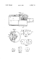
- FIG. 1 is a partially cut side view of said coupling
- FIG. 2 is a partially cut end view of the same along the line 2--2 in FIG. 1,
- FIG. 3 is an end view of a means included in the coupling head of said coupling
- FIG. 4 is a plan view of said means
- FIGS. 5, 6 and 7 show one of these sliding blocks as seen from one of its ends, from above and from behind, respectively.
- FIG. 1 shows that the shown embodiment of a sliding block coupling according to the present invention comprises a coupling head 1.
- This comprises devices 2,3 for arranging an ingoing, driving, and an outgoing, driven, torque-transferring member rotating together with the coupling head, and sliding blocks 4 arranged in a cylindrical recess 5 positioned perpendicular to the rotation axis of the coupling head so as to, in cooperation with the coupling head, transfer torque from one of said members to the other.
- the shown coupling head 1 consists of a substantially cylindrical body intended to rotate about its geometrical axis. Both ends of said body are provided with axial bores 6 and 7 in which the driven and the driving torque-transferring members can be inserted to engage with the coupling head 1.
- FIGS. 1 and 2 only one of both said torque-transferring members, namely a spindle 8, is shown, one end of said spindle being inserted in the axial bore 7, in which said spindle, via splines 9, is in torque-transferring engagement with the head 1 via a means 3 which, according to the invention, is included in said devices for arranging one of the two torque-transferring members and is arranged in the cylindrical recess 5 in the coupling head.
- the other torque-transferring member can, for example, consist of a shaft pin whose free end is insertable into the bore 6 in the coupling head where it suitably is engaged with the splines 2 which also are included in said devices for arranging both of the torque-transferring members, and is arranged in the wall of the bore 6 in the usual manner.
- the means 3 is torque-transferring between the spindle 8 and the sliding blocks 4 and, for this purpose, is extended in the longitudinal direction of the recess 5 and, as is especially well-revealed by FIGS. 3 and 4, provided with projections or recesses bounded by flats 10 at least in the proximity of both of its sides or on opposite sides of the same, on or in which projections or recesses the sliding blocks 4 are arranged between the means in question and the wall in the cylindrical recess 5.
- the means has a bore 11 corresponding to the bore 7 in the coupling head 1, in whose wall the splines 9 are arranged, with which an end of the spindle 8 projecting into the coupling head 1 is in torque-transferring engagement with corresponding splines.
- the spindle 8 is held in the means by means of a locking pin 12 which is inserted in a bore 13 arranged diametrically through the means 3 and the spindle 8. In order to achieve locking, access to said bore 13 can be had through another bore 14 extending diametrically through the coupling head 1.
- the means 3, together with the sliding blocks 4, being designed to in a suitable manner fill the cylindrical recess 5 transversely through the coupling head 1, and by means of its furthermore being provided with ends designed as spherical surfaces 15, the means 3, together with the spindle 8, can carry out restricted swinging movements in all directions in relation to the coupling head 1, whereby the entire arrangement obtains the charactor of a universal joint.
- the means 3 receives longitudinal positioning by means of its ends or spherical surfaces 15 abutting the inside of a casing 16 surrounding the coupling head 1 and fixed in relation to the same, for example, by means of bolts 17.
- the casing 16 also holds the sliding blocks in the spaces intended for them between the means 3 and the wall in the cylindrical recess 5. Furthermore, the casing 16 also serves to cover both ends of the cylindrical recess in the coupling head 1. By means of this covering, the spaces for both of the pairs of sliding blocks 4 are sealed outwardly as regards lubricating grease. In order to ensure that the sliding block spaces are also inwardly sealed with respect to lubricating grease, annular seals in the form of rubber discs 17 are suitably arranged between the wall in the cylindrical recess 5 in the coupling head 1 and the means 3 arranged in said recess.
- seals or discs 17 are situated inside the ends of the means provided with projections or recesses and are held in annular grooves 18 in the means while their outer edges abut the wall in the recess 5.
- the casing 16 around the coupling head 1 is also sealed in relation to the same by means of a pair of O-rings 19 which are situated in annular grooves about the coupling head near both ends of the casing 16, the inner sides of said edges being abutted by said O-rings.
Landscapes
- Engineering & Computer Science (AREA)
- General Engineering & Computer Science (AREA)
- Mechanical Engineering (AREA)
- Earth Drilling (AREA)
- Mechanical Operated Clutches (AREA)
- Golf Clubs (AREA)
Applications Claiming Priority (2)
| Application Number | Priority Date | Filing Date | Title |
|---|---|---|---|
| SE7607714 | 1976-07-06 | ||
| SE7607714A SE409751B (sv) | 1976-07-06 | 1976-07-06 | Glidblockskoppling |
Related Parent Applications (1)
| Application Number | Title | Priority Date | Filing Date |
|---|---|---|---|
| US05811978 Continuation | 1977-06-30 |
Publications (1)
| Publication Number | Publication Date |
|---|---|
| US4324113A true US4324113A (en) | 1982-04-13 |
Family
ID=20328408
Family Applications (1)
| Application Number | Title | Priority Date | Filing Date |
|---|---|---|---|
| US05/971,883 Expired - Lifetime US4324113A (en) | 1976-07-06 | 1978-12-21 | Sliding block coupling |
Country Status (8)
| Country | Link |
|---|---|
| US (1) | US4324113A (de) |
| JP (1) | JPS536755A (de) |
| DE (1) | DE2730349A1 (de) |
| ES (1) | ES460408A1 (de) |
| FR (1) | FR2357778A1 (de) |
| GB (1) | GB1580336A (de) |
| IT (1) | IT1079864B (de) |
| SE (1) | SE409751B (de) |
Cited By (3)
| Publication number | Priority date | Publication date | Assignee | Title |
|---|---|---|---|---|
| WO2008107288A1 (de) * | 2007-03-02 | 2008-09-12 | Schaeffler Kg | Gleichlauffestgelenk, übertragungsvorrichtung mit dem gleichlauffestgelenk sowie verfahren zur herstellung des gleichlauffestgelenks |
| US20120244954A1 (en) * | 2009-11-13 | 2012-09-27 | Sms Siemag Aktiengesellschaft | Sliding block for an articulated spindle |
| DE102007010083B4 (de) * | 2007-03-02 | 2020-04-16 | Schaeffler Technologies AG & Co. KG | Gleichlauffestgelenk, Übertragungsvorrichtung mit dem Gleichlauf-festgelenk sowie Verfahren zur Herstellung des Gleichlauffestgelenks |
Families Citing this family (1)
| Publication number | Priority date | Publication date | Assignee | Title |
|---|---|---|---|---|
| JPS5829300Y2 (ja) * | 1978-11-15 | 1983-06-27 | トヨタ自動車株式会社 | 歯車変速機 |
Citations (13)
| Publication number | Priority date | Publication date | Assignee | Title |
|---|---|---|---|---|
| US919651A (en) * | 1907-09-10 | 1909-04-27 | Clarence W Spicer | Universal joint. |
| US1112869A (en) * | 1912-12-28 | 1914-10-06 | Edward J Tirrell | Universal joint. |
| US1346253A (en) * | 1917-09-20 | 1920-07-13 | George T Rayfield | Universal coupling |
| US1413848A (en) * | 1921-05-19 | 1922-04-25 | Int Motor Co | Universal joint |
| US1527958A (en) * | 1918-10-02 | 1925-02-24 | Western States Machine Co | Means for mounting and driving centrifugal machines |
| US1834906A (en) * | 1929-02-27 | 1931-12-01 | Cleveland Steel Products Corp | Universal joint |
| US2117706A (en) * | 1936-12-14 | 1938-05-17 | Cutting Sales & Engineering Co | Two-bearing universal joint |
| US2559108A (en) * | 1948-10-01 | 1951-07-03 | Sr Adolf Boge | Universal joint |
| US2752766A (en) * | 1952-04-04 | 1956-07-03 | Wildhaber Ernest | Laminated mounting and connection, especially for universal joints |
| US2896430A (en) * | 1958-03-10 | 1959-07-28 | Gordon L Olson | Flexible coupling construction |
| US3001387A (en) * | 1958-06-11 | 1961-09-26 | Gen Motors Corp | Torque transmitting slip joint |
| US3914959A (en) * | 1973-05-29 | 1975-10-28 | Morgaardshammar Ab | Improvements in sliding block in sliding block coupling |
| US3975922A (en) * | 1974-05-13 | 1976-08-24 | Glaenzer Spicer | Homokinetic transmission joint |
Family Cites Families (4)
| Publication number | Priority date | Publication date | Assignee | Title |
|---|---|---|---|---|
| US1316733A (en) * | 1919-09-23 | Flexible coupling | ||
| FR1389210A (fr) * | 1964-03-18 | 1965-02-12 | Beteiligungs & Patentverw Gmbh | Tête de broche articulée |
| SE313287B (de) * | 1966-02-16 | 1969-08-11 | Morgaardshammar Ab | |
| SE373051B (de) * | 1972-05-03 | 1975-01-27 | Morgaardshammar Ab |
-
1976
- 1976-07-06 SE SE7607714A patent/SE409751B/xx unknown
-
1977
- 1977-06-29 IT IT50044/77A patent/IT1079864B/it active
- 1977-07-04 GB GB27975/77A patent/GB1580336A/en not_active Expired
- 1977-07-04 FR FR7720478A patent/FR2357778A1/fr not_active Withdrawn
- 1977-07-05 ES ES460408A patent/ES460408A1/es not_active Expired
- 1977-07-05 DE DE19772730349 patent/DE2730349A1/de not_active Withdrawn
- 1977-07-05 JP JP8090877A patent/JPS536755A/ja active Pending
-
1978
- 1978-12-21 US US05/971,883 patent/US4324113A/en not_active Expired - Lifetime
Patent Citations (13)
| Publication number | Priority date | Publication date | Assignee | Title |
|---|---|---|---|---|
| US919651A (en) * | 1907-09-10 | 1909-04-27 | Clarence W Spicer | Universal joint. |
| US1112869A (en) * | 1912-12-28 | 1914-10-06 | Edward J Tirrell | Universal joint. |
| US1346253A (en) * | 1917-09-20 | 1920-07-13 | George T Rayfield | Universal coupling |
| US1527958A (en) * | 1918-10-02 | 1925-02-24 | Western States Machine Co | Means for mounting and driving centrifugal machines |
| US1413848A (en) * | 1921-05-19 | 1922-04-25 | Int Motor Co | Universal joint |
| US1834906A (en) * | 1929-02-27 | 1931-12-01 | Cleveland Steel Products Corp | Universal joint |
| US2117706A (en) * | 1936-12-14 | 1938-05-17 | Cutting Sales & Engineering Co | Two-bearing universal joint |
| US2559108A (en) * | 1948-10-01 | 1951-07-03 | Sr Adolf Boge | Universal joint |
| US2752766A (en) * | 1952-04-04 | 1956-07-03 | Wildhaber Ernest | Laminated mounting and connection, especially for universal joints |
| US2896430A (en) * | 1958-03-10 | 1959-07-28 | Gordon L Olson | Flexible coupling construction |
| US3001387A (en) * | 1958-06-11 | 1961-09-26 | Gen Motors Corp | Torque transmitting slip joint |
| US3914959A (en) * | 1973-05-29 | 1975-10-28 | Morgaardshammar Ab | Improvements in sliding block in sliding block coupling |
| US3975922A (en) * | 1974-05-13 | 1976-08-24 | Glaenzer Spicer | Homokinetic transmission joint |
Cited By (4)
| Publication number | Priority date | Publication date | Assignee | Title |
|---|---|---|---|---|
| WO2008107288A1 (de) * | 2007-03-02 | 2008-09-12 | Schaeffler Kg | Gleichlauffestgelenk, übertragungsvorrichtung mit dem gleichlauffestgelenk sowie verfahren zur herstellung des gleichlauffestgelenks |
| DE102007010083B4 (de) * | 2007-03-02 | 2020-04-16 | Schaeffler Technologies AG & Co. KG | Gleichlauffestgelenk, Übertragungsvorrichtung mit dem Gleichlauf-festgelenk sowie Verfahren zur Herstellung des Gleichlauffestgelenks |
| US20120244954A1 (en) * | 2009-11-13 | 2012-09-27 | Sms Siemag Aktiengesellschaft | Sliding block for an articulated spindle |
| US9228615B2 (en) * | 2009-11-13 | 2016-01-05 | Sms Group Gmbh | Sliding block for an articulated spindle |
Also Published As
| Publication number | Publication date |
|---|---|
| GB1580336A (en) | 1980-12-03 |
| IT1079864B (it) | 1985-05-13 |
| SE409751B (sv) | 1979-09-03 |
| ES460408A1 (es) | 1978-05-01 |
| DE2730349A1 (de) | 1978-01-12 |
| JPS536755A (en) | 1978-01-21 |
| FR2357778A1 (fr) | 1978-02-03 |
| SE7607714L (sv) | 1978-01-07 |
Similar Documents
| Publication | Publication Date | Title |
|---|---|---|
| US4178778A (en) | Homokinetic joint of the tripod type | |
| US4324113A (en) | Sliding block coupling | |
| US2681552A (en) | Flexible coupling | |
| US2986022A (en) | Constant velocity joint | |
| JPS60211124A (ja) | 自在継手 | |
| US4395246A (en) | Universal joint | |
| US2760358A (en) | Universal joint | |
| GB2040397A (en) | Universal joints | |
| US3106076A (en) | Universal joints | |
| US4634402A (en) | Universal joint capable of accommodating thrust loads | |
| US2595513A (en) | Coupling for rotating shafts | |
| US1440648A (en) | Universal joint | |
| US7594857B2 (en) | Double Cardan joint | |
| US2234296A (en) | Constant velocity universal joint | |
| US3332256A (en) | Universal joint | |
| US3429143A (en) | Universal joint | |
| US3798925A (en) | Universal coupling | |
| US2263279A (en) | Joint for the connection of shafts | |
| RU2149291C1 (ru) | Универсальный шарнир | |
| US2648581A (en) | Motion transmitting connection | |
| KR200192541Y1 (ko) | 동력전달용 축이음장치 | |
| US2206735A (en) | Constant velocity joint | |
| JPH03223525A (ja) | 動力伝達継手 | |
| US1390668A (en) | Universal joint | |
| US1996688A (en) | Universal joint for motor vehicles |
Legal Events
| Date | Code | Title | Description |
|---|---|---|---|
| STCF | Information on status: patent grant |
Free format text: PATENTED CASE |